1
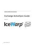
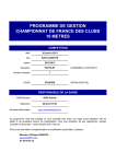
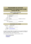
90PF Dual Channel Programmable Filter/Amplifier Card USER’S MANUAL 90PF Dual Channel Programmable Filter/Amplifier Card Contents, Figures and Tables CONTENTS Section 1 - Front Panel Operation 1.1 Start-Up 1.2 90PF Operation Instructions 1.3 Front Panel Command Structure Section 2 – Software Installation 2.1 CDFC-01 Installation Disk 2.2 Remote Software Installation 2.3 Uninstall Page 2 2 3 5 6 7 Section 3 – Remote Operation 3.1 Instructions 3.2 90PF Slot Card Command Reference 3.3 Main Soft Front Panel 3.4 Functional Groups 8 9 12 12 APPENDIX A 14 FIGURES Figure 1 Front Panel 2 Components of Soft Front Panel Page 2 12 TABLES Table 1.0 90PF Command Examples 2.0 90PF Command Set Page 9 9-11 1 1784 Chessie Lane, Ottawa, IL 61350 • Tel: 800/252-7074, 815/434-7800 • FAX: 815/434-8176 e-mail: [email protected] • Web Address: http://www.freqdev.com 90PF Slot Card Section 1 Front Panel Operation Dual Channel Programmable Filter/Amplifier Card 1.1 - Start Up All 90PF slot cards should be inserted into the 90IP chassis and controller while the power switch (rear panel) is in the OFF position (O). Once slot cards have been inserted, the power switch can be moved to the ON position (I). Upon power-up, a micro-controller on each 90PF slot card sends its configuration to the 90IP controller which displays the 90PF configuration. This is Frequency Devices’ smartSLOT Technology. See 90IP Operations Manual for chassis and controller operating instructions. See Figure 1 - Front Panel below Figure 1 – Front Panel 1.2 - 90 PF Operation Instructions 1. Upon power up, a cursor appears under the default function value or mode. (Note the cursor is initially displayed on the LSB of any numerical value.) 2. Turning the FUNCTION knob scrolls the cursor through the various function selections. 3. To make a change, press the ENTER button and the addressed character will blink. 4. Turning the SELECT knob will alter the value of the desired character or mode. 5. Pressing the ENTER button again, loads the selected value or configuration into the slot card and controller memory and the blinking stops. 6. If a question mark (?) appears in the display, an invalid entry has been made and that value or mode must be corrected. Example: Frequency values outside permitted tuning ranges. 7. After a valid change is accepted by pressing the ENTER key, another function value or mode may be selected by using the FUNCTION and SELECT knobs. 8. Once the channel is programmed or configured, it may also be saved in one of the nine configuration locations. Since it is the most recent configuration setting, it automatically becomes the new power-up default for that channel. 9. User must press ENTER button to select and activate all configurations. This is done on a per channel basis. 2 1784 Chessie Lane, Ottawa, IL 61350 • Tel: 800/252-7074, 815/434-7800 • FAX: 815/434-8176 e-mail: [email protected] • Web Address: http://www.freqdev.com 90PF Slot Card Section 1 Front Panel Operation Dual Channel Programmable Filter/Amplifier Card 90PF slot cards can be addressed from either the 90IP hard front panel or by using a computer controlled soft front panel via the GPIB or RS232 communication port on the rear of the 90IP chassis. See page 5 for Remote Operation instructions. Operating functions with available ranges or acceptable modes are listed below in the command structure listing. 1.3 - Front Panel Command Structure 1. ADD – Identifies current chassis location within the GPIB communication system structure. For an individual chassis, the default address will read “01”. 00 thru 30 ADD 6. FREQ – Selects the desired corner frequency of the filter module. Frequency selection can be performed sequentially or by setting each individual digit. Tuning Range Step 0.1 Hz to 100 Hz 0.1 Hz FREQ 101 Hz to 1000 Hz 1.0 Hz 1.01 kHz to 10.0 kHz 10.0 Hz 10.2 kHz to 300 kHz 200 Hz 2. SLOT – Each 90IP chassis can be populated with one (1) to four (4) slot cards. This command allows the user to independently select and configure each slot card. 1 thru 4 SLOT 7. INPUT – User can select single-ended or differential input. S – Single Ended INPUT D - Differential Note: Output is always single ended. 3. CHAN – Each 90PF slot card contain two (2) channels of programmable gain and filtering. The CHAN command allows the user to independently select and configure each 90PF channel. 01 or 02 CHAN 8. GAIN IN – Pre filter gain. Gain selection is performed sequentially. Tuning Range Step 0 dB to 60 dB 5.0 dB GAIN IN 4. FIL – Upon insertion of a 90PF slot card, smartSLOT Technology in the 90IP chassis automatically configures the controller based on the customer specified filter module. Filter type, number of poles and filter transfer function are configured upon power-up after insertion of the slot card. Type P Transfer Function 8 B - Butterworth FIL LP- Low Pass HP –High Pass L - Bessel E – Elliptic 88 Y – Elliptic 100 C – Constant delay 80 D– Constant delay 100 9. GAIN OUT – Post filter gain. Gain selection is performed sequentially. Tuning Range Step 0 dB to 20 dB 1.0 dB GAIN OUT 10. OFFSET – Offset for each card is preset at room temperature. Because of thermal drift and high gain settings, fine-tuning of DC offset is sometimes required. Offset adjustment is performed sequentially. Tuning Range Step -100 mV to 100 mV 1.0 mV OFFSET 5. MODE – Determines signal path and coupling requirements for the input signal. Normal represents the signal passing through the filter module. By-Pass removes the filter module from the signal path, while maintaining access to the amplifier functions. AC– AC coupled input N - Normal MODE DC– DC coupled Input B – By Pass 3 1784 Chessie Lane, Ottawa, IL 61350 • Tel: 800/252-7074, 815/434-7800 • FAX: 815/434-8176 e-mail: [email protected] • Web Address: http://www.freqdev.com 90PF Slot Card Section 1 Front Panel Operation Dual Channel Programmable Filter/Amplifier Card 11. CHAN CFG – For slot cards that have a high-pass filter in channel 1 and a low-pass filter in channel 2, Channel Configuration (CHAN CFG) allows each channel to operate independently (DUAL) or to operate in a band-pass or band-reject mode. Utilize each channel independently DUAL Band Pass Operation *B-PASS Band Reject (Notch) Operation *B-REJECT *Band Pass (B-PASS) and Band Reject (B-REJECT) can be selected during configuration of channel 1 or channel 2. The slot card must have a high pass filter in channel 1 and a low pass filter in channel 2. For BPASS operation, input signal must be connected to channel one (1) input BNC and filtered output signal will exit through channel two (2) output BNC. For BREJECT operation, input signal must enter through both channel (1) and channel (2) input BNC’s. Filtered output signal will exit through channel two (2) output BNC. 13. REMOTE – Displays Local reset screen when external computer has control of the instrument in remote operation. On power-up, Instrument defaults to local mode. During a remote session, press ENTR to return to local mode. An external computer can only initiate remote mode. REMOTE LCL - Local ENTR – RS232 or GPIB 14. LED’s – Each 90PF contains two clipping sections per channel, one for the pre-gain output and one for the post-gain output. These outputs are the inputs into the clipping circuitry. The inputs pass through a comparator. When peak voltage is greater than +10.5V or less than –10.5V, CLIPPING occurs and the red I/O LED’s will light. 12. CONFIG – Up to 9 configurations can be saved on each 90PF slot card. Slot card configuration, in use at time of power-OFF, will be saved to the next power ON cycle. Select 1 thru 9 CONFIG S - Saved 4 1784 Chessie Lane, Ottawa, IL 61350 • Tel: 800/252-7074, 815/434-7800 • FAX: 815/434-8176 e-mail: [email protected] • Web Address: http://www.freqdev.com 90PF Section 2 Software Installation Dual Channel Programmable Filter/Amplifier Card 2.1 – CDFC-01 Installation Disk The CDFC-01 Installation Disk contains documents in Word and PDF format that include individual slot card data sheets, User’s Manuals, slot card drivers, set-up directories for each slot card user interface and instrument control software. 2.1.1 Slot Card Drivers 90FC Instrument Driver Directory (Used for Custom Applications) This directory will install the code and files needed to develop custom applications for each slot card. 2.1.2 Set-Up Directory for Slot Card Interface (Used for Custom GUI Development) 90PF User Interface Directory - This directory installs the code and files used in developing a custom 90PF slot card GUI. 2.1.3 Setup Directory for Instrument Control Software 90IP Instrument Control Directory This directory installs the LAUNCH SLOT CARD CONTROL software and the 90IP INSTRUMENT SLOT CARD CONTROLLER CONFIGURATION software. The Slot Card Controller (SCC) is used to read and set the configuration of valid slot cards. The SCC performs the following functions: • Provides communication with the controller interface, • Provides slot card access, • Provides slot card set-up, and • Discontinues slot card operation (Stopping). It is designed to allow the user to select the slot card configuration through the software front panel. By setting the values with the soft front panel, the software automatically configures the slot card without the need to use the 90IP hard front panel instrument controls. For this to occur, the SCC monitors event changes in each soft panel control and runs various routines accordingly. Multiple slot cards may be arranged to work simultaneously without affecting each other. 5 1784 Chessie Lane, Ottawa, IL 61350 • Tel: 800/252-7074, 815/434-7800 • FAX: 815/434-8176 e-mail: [email protected] • Web Address: http://www.freqdev.com 90PF Section 2 Software Installation Dual Channel Programmable Filter/Amplifier Card 2.2 – Remote Software Installation CRITICAL: For Windows 2000 or Windows XP Installations see Appendix A 90PF installation tools use Microsoft Windows Installer (MSI) technology to install the necessary 90PF development tools for remote operation. This software suite was developed using National Instruments’ LabWindows/CVI Version 6.0 environment following rules established in the VXIplug&play instrument driver architecture and the IVI (Interchangeable Virtual Instrument) Foundation Standards. As such, certain libraries, drivers, and “software engines” are required in the recipient PC for the proper operation of the application software. This is true for either application end-users or software developers. In the case of software developers, the installation of additional tools may depend on the development environment and/or any other tools needed to open/review or edit the development files supplied with the software suite. For users requiring remote operation every tool MUST be installed to be able to remotely operate 90IP/Slot Cards. The 90IP uses the following National Instruments’ (NI) engines and drivers with their corresponding components: 1. NI-488.2 1.70- for applications using GPIB. 2. NI VISA 2.6 Run-time Engine – application programming interface (API) that defines interfaceindependent features and standards for instrument drivers. 3. IVI Engine 1.83 - the IVI engine is in the form of a 32-bit DLL. The IVI engine requires that you install VISA, but it is not dependent on any other library. 4. Measurement & Automation Explorer 2.2 - to provide devices access and to configure hardware and software. Follow the instructions to install 90PF utilities into a local directory: Insert the CDFC-01 disk into your CD-ROM. Access the setup executable either by using the Start/Run/Browse popup window or by using Windows Explorer on your Windows operating system. Select the 90FC Instrument Driver folder. Double-click on Setup.exe to install the 90IPxxx Function Cards Driver software. Verify that files reside in the selected target PC directory. Select the 90PF User Interface folder. Double-click on Setup.exe to install the 90PF User Interface software. Verify that files reside in the selected target PC directory. Select the 90IP Instrument Control folder. Double-click on Setup.exe to install the 90IP Instrument Control software. If “Complete” is selected, a complete installation of the 90IP Instrument Control software includes: NI-MAX 2.2.0, NI Remote Provider for MAX, NI Software Provider for MAX, NI-488.2 for Windows, NI GPIB Provider for MAX, NI-VISA 2.6 Run-time Engine, NI-VISA MAX Provider 2.6.1f2, NI-VISA Server 1.0.0f6, NIIVI engine 1.83, NI-IVI Provider for MAX, and the 90IP-related software. Note that depending on the software/hardware conditions on the target PC you may want to run a custom installation and select only the features that you need for remote operation. CAUTION! Check NO when the NI reboot windows appear during driver/libraries installation. Do not reboot until the end of the install procedure, where a single popup windows prompts you for a restart. The installation process should not be interrupted with a reboot, otherwise installation must be restarted from the beginning. After installation and reboot, verify that the files reside in the selected target PC directory. An FDI icon should appear on you desktop. Note that verification of installed files after each step on the hard drive is optional. For serial remote operation: With the 90IP unit turned ON and the RS232 cable connected to COM1 or 2, RUN the NI-MAX 2.2.0 by clicking on the NI icon on the desktop, this updates the configurations. Wait for the data to be updated, indicated by no MAX or hard drive activity. Quit the MAX application window. Before initiating the remote mode for the 90IP, verify that it is powered up, connected to the PC via the RS232 cable and that the display is not in remote mode. Initiate the 90IP Instrument Control from the FDI desktop icon: Select RS232, and COM1 or 2 on the 90IP GUI. CLICK on Scan and this operation will produce: ASRL<COM>::INSTR in the “Instruments” display window. CLICK on the items as they appear in the windows until the 90PF GUI appears. Verify that remote control of the PF card is functional (One can actually 6 1784 Chessie Lane, Ottawa, IL 61350 • Tel: 800/252-7074, 815/434-7800 • FAX: 815/434-8176 e-mail: [email protected] • Web Address: http://www.freqdev.com 90PF Section 2 Software Installation Dual Channel Programmable Filter/Amplifier Card hear relays clicking for certain button changes in I/O). When finished, use the Quit button to exit the application. Using RS232 remote operation, after quitting a remote session, press the ENTER button on the 90IP to return to local mode or turn the power button off and on, to reset the instrument. For GPIB remote operation: Connect a GPIB cable from the instrument to the PC, and turn ON (I) the 90IP. Initiate the 90IP Instrument Control from the desktop icon: Select GPIB then CLICK on the Scan button: GPIB0::1::INSTR should appear in the “Instruments” display window. CLICK on items as they appear in the windows until the 90PF GUI appears. Verify that control of the PF card is functional. Use the Quit button to exit application. 2.3 - Uninstall Executing setup toggles between install and uninstall. To uninstall all the 90IP related software from the target PC, you may use the CDFC-01 disk. Uninstall is initiated from CD setup folders. Each time this is done, the software toggles between install and uninstall. However, even though the NI libraries auto setup, they do not uninstall automatically. The NI libraries must be uninstalled separately using Add/Remove Programs in Control Panel. The list is as follows, NI IVI engine 1.83, NI-MAX 2.2.0, NI-488.2 1.70, NI VISA 2.6 Run-time Engine, and NI-VISA Server 1.0.0f6. 7 1784 Chessie Lane, Ottawa, IL 61350 • Tel: 800/252-7074, 815/434-7800 • FAX: 815/434-8176 e-mail: [email protected] • Web Address: http://www.freqdev.com 90PF Section 3 Remote Operation Dual Channel Programmable Filter/Amplifier Card up of each channel configuration on the slot card. At power down, the GUI will show the last used settings of the slot card. 3.1 - Instructions: 1. Insert the CDFC-01, CD into the PC, CDROM. Using Microsoft Explorer, select the Instrument Control Directory and “CLICK” setup. 2. Follow instructions and the software will place an icon on your desktop and in your Program startup menu. 3. Connect the appropriate cable RS232 or GPIB to the PC’s interface card and the 90IP. 4. “DOUBLE CLICK” on the 90IP icon and the instrument controller set up Graphical User Interface (GUI) will appear. 5. Select GPIB or RS232. For RS232, select the COM port (1 or 2) location where the RS232 interface card is installed in your PC. 6. “CLICK” on SCAN, this will display an instrument list. “CLICK” or highlight the desired chassis, this will display an instrument list of slot cards installed in the 90IP chassis. See Figure 2 and read Section 2.4 for a detailed description of the above commands. 7. “CLICK” or highlight a slot card, this will launch the slot card GUI onto the PC screen, allowing setTo Reactivate the Soft Front Panel after shut down, steps four (4) through seven (7) of the above procedure must be performed. 8 1784 Chessie Lane, Ottawa, IL 61350 • Tel: 800/252-7074, 815/434-7800 • FAX: 815/434-8176 e-mail: [email protected] • Web Address: http://www.freqdev.com 90PF Section 3 Remote Operation Dual Channel Programmable Filter/Amplifier Card 3.2 - 90PF Slot Card Command Reference For 90PF slot card drivers see Set-Up Disk CDFC-01, Frequency Devices FD90IPxxx Cards Reference Document. This document includes the commands, syntax, parameters, expected return values, and error codes to consider when developing a software system using the instrument driver to configure the 90PF card or any other valid function card. CDFC-01 also contains Frequency Devices 90IP/PF Card Online Help. 3.2.1 - Command Syntax and Format To communicate with the 90IP, use ASCII characters. The commands must be issued in UPPER CASE ONLY and cannot contain any number of embedded space characters. A command to the 90IP consists of a command mnemonic with optional ?, optional =, arguments if necessary, and a command terminator. In RS232, the command terminator is a <lf> (line feed) or (0A)x. In GPIB, the terminator is a linefeed <lf> or EOI. It is important to note that the command terminator is embedded automatically when issuing commands through GPIB. The user/developer need not to worry about adding the command terminator to commands using GPIB. This means, for example, that you may need to “drop” the “\n” character from the string you are using as a command. No command processing occurs until a command terminator is received. No command processing occurs until a command terminator is received. The commands are interpreted in the same way in either RS232 or GPIB. Values returned by the 90IP are sent as a string of ASCII characters terminated by <lf> (line feed) or (0A)x. Table 1 shows examples of 90PF commands. Command FREQ?\n CUPL?\n SNGL\n BP\n CARD=1\n PRE=10\n 1. Function Query the frequency setting of the active card/channel. Query the coupling mode of the active card/channel. Set the active card/channel to single-ended output mode. Configure the active card channels as a band-pass filter Set the card in slot one, “active”1. Set the pre-gain of the active card/channel to 10dB. Active means to receive the focus. Every configuration command issued after this one will affect the card in the specified slot. The \n character is dropped in GPIB communication. Table 1 - 90PF Command Examples. When a command is issued, the instrument controller writes a command to the 90IP first, and then reads the result from it. If the command is a valid query command, the 90IP will return the required information as a string of ASCII characters. For instrument parameter configuration commands, a hexadecimal number 00 is returned to show the controller that the command has been executed successfully. If an error occurs, a hexadecimal number 55 will be returned. All returned messages from the 90IP will terminate with a linefeed <lf> or (0A)x. Table 2 defines the 90PF command set. Note: The expected values are responses from the 90IP with no software driver processing. Command IDN? GPIB? WHO? Function Expected/Set to Value Returns a string representing the “FreqDev,90IP\n” instrument’s identification name. Returns a string representing the A value from 00 to 30. instrument’s GPIB primary address. Returns a string list representing the cards “CARD 1,2,3,4\n” for a fully loaded 90IP. present in the 90IP slots. The list will show every card properly inserted into a slot and loaded into the 90IP. 9 1784 Chessie Lane, Ottawa, IL 61350 • Tel: 800/252-7074, 815/434-7800 • FAX: 815/434-8176 e-mail: [email protected] • Web Address: http://www.freqdev.com 90PF Section 3 Remote Operation CARD? CHAN? FREQ? PRE? POS? FIL? CUPL? INPUT? OUTPUT? OFFSET? BP BR DUAL DC AC BYPS NORM SNGL DIFF CARD=n CHAN=n FREQ=xyyyxU PRE=xy Dual Channel Programmable Filter/Amplifier Card Returns a string representing the active “2 CHAN FILTER\n” for a 2 channel filter type card type. card. Returns a string representing the active Channel type: “L8D\n”, “L8E\n”, “L8B\n”, channel type. This is valid only on channels “L8L\n”, “H8D\n, H8B\n”, etc of function-based cards. Returns a string value representing the Frequency setting: “10.00KHz”, “10.00 Hz”, active card/channel frequency setting. etc. Returns a string value representing the A value from 00dB to 60dB in 5dB active card/channel pre-gain setting. increments. Returns a string value representing the A value from 00dB to 20dB in 1dB active card/channel post-gain setting. increments. Returns a string representing the active “SUM\n”, “CAS\n” or “DUAL\n”. card function type setting. Returns a string representing the active “AC\n” coupled or “DC\n” coupled. card coupling mode setting. Returns a string representing the active “SNGL\n” single-ended or “DIFF\n” card input mode setting. differential-ended. Returns a string representing the active “NORM\n” active channel or “BYPS\n” bycard output mode setting. passed channel. Returns a string value representing the A value from “-100mV” to “100 mV”, for active card DC offset setting. example: “-05 mV”, “09 mV”, “10 mV”, etc. Sets the channel configuration of active Configure two channels as a band-pass filter. card channels to band-pass filter. Sets the channel configuration of active Configure two channels as a band-reject card channels to band-reject filter. filter. Sets the channel configuration of active Configure the filter card as dual independent card channels as independent filters. channels. Sets the coupling mode of an active card Set DC coupled mode. channel to DC. Sets the coupling mode of an active card Set AC coupled mode. channel to AC. Sets the output mode of an active card The channel filter is bypassed. channel to by-pass. Sets the output mode of an active card The current channel filter is activated. channel to normal. Sets the input mode of an active card Set the current channel to the single-ended channel to single-ended. mode. Sets the input mode of an active card Set the current channel to the differentialchannel to differential-ended. ended mode. Select a card where n is 1, 2, 3 or 4. Selects an active card. Select a channel where n is 1 or 2. Selects an active card channel. Sets the frequency of an active card Set the frequency where x can be any channel. number from 0 to 9 and y can be any number from 0 to 9 or a . (point). U represents the units “K” for kilo Hertz or “” (empty) for Hertz. Set the pre-gain where x can be any number Sets the pre-gain of an active card channel. from 0 to 6, and y can be 0 or 5. Leading zeroes may be dropped. 10 1784 Chessie Lane, Ottawa, IL 61350 • Tel: 800/252-7074, 815/434-7800 • FAX: 815/434-8176 e-mail: [email protected] • Web Address: http://www.freqdev.com 90PF Section 3 Remote Operation Dual Channel Programmable Filter/Amplifier Card POS=xy Sets the post-gain of an active card channel. SAV=n Saves the parameter settings of a card/channel to a specific configuration from a list of configurations. This set will contain the active card/channel parameter value settings. OFFSET=sxyy CFG=n Set the post-gain where x can be any number from 0 to 2, and y can be 0 to 9. Leading zeroes may be dropped. Save current parameters into a configuration where n is a value from 1 to 9. Set the offset where s is the sign NOT used in positive numbers, x is a number from 0 to Sets the dc offset of an active card 1, and y is a number from 0 to 9. Numbers channel. are left justified. Leading zeroes may be dropped. Initializes the parameters of a card/channel Restore parameters from a configuration into to a specific configuration from a list of active card parameters where n is a value configurations. This set will configure the from 1 to 9. active card/channel. Table 2 – 90PF Command Set 11 1784 Chessie Lane, Ottawa, IL 61350 • Tel: 800/252-7074, 815/434-7800 • FAX: 815/434-8176 e-mail: [email protected] • Web Address: http://www.freqdev.com 90PF Section 3 Remote Operation Dual Channel Programmable Filter/Amplifier Card 3.3 - Main Soft Front Panel The components of the main panel are shown in Figure 2: 3 2 4 5 6 7 8 9 10 1 14 13 12 11 Figure 2 - Components of the Soft Front Panel. 3.4 - Functional Groups The main panel is divided into three functional groups: Command, Function and Configuration. The Command Group allows the user to initiate certain process/system commands. The Function Group presents the filter type contained on each channel. Finally, the Configuration Group contains the controls necessary to set different configuration parameters into the 90PF. 12 1784 Chessie Lane, Ottawa, IL 61350 • Tel: 800/252-7074, 815/434-7800 • FAX: 815/434-8176 e-mail: [email protected] • Web Address: http://www.freqdev.com 90PF Section 3 Remote Operation Dual Channel Programmable Filter/Amplifier Card 3.4.1 Command Group 1 - Quit Command Button: Use this command button whenever you want to exit/close the software. It will then no longer allow configuration changes; close the function card panel and turn-off the SCC without affecting any other active slot card process. 3.4.2 Function Group 2 - Filter Indicator: After the card information is successfully loaded into the 90IP instrument during power-up, this indicator identifies the filter type for each channel. The displayed information will remain constant while the configuration process is in execution. 3.4.3 Configuration Group 3 - Channel Configuration Control: Use Channel Config to select the channel configuration desired for each slot card based on the available filter modules. Select Dual to independently operate each channel, Band Pass for band-pass filter settings, and Band Reject for band-reject filter settings. Default value shown at startup is typically “Dual”. You must verify the Filter Indicator (Item 2) on both channels to see if the selected configuration can be accomplished. If the slot card is not configured with a high-pass and low-pass filter the band-pass and band-reject options cannot be implemented. 4 - Input Configuration Controls: Use these controls to select the input configuration modes for the slot card. Set the coupling mode for each channel in the function card with the AC/DC control. Select AC for AC coupling mode or DC for DC coupling mode. 5 – Input Mode Selection: Sets the input mode for each channel in the slot card. Select Single-Ended for single-ended input operation or Differential for differential input mode. 6 - Output Configuration Control: Use this control to select the output configuration for the channel on the slot card. Select Normal to filter the input signal or Bypass to remove the filter from the signal path. 7 – Pre-Gain Control: This control sets the filter pre-gain (0 to 60 in 5dB steps) for each channel on the slot card. 8 – Post-Gain Control: This control sets the filter post-gain (0 to 20 in 1dB steps) for each channel on the slot card. 9 - Offset Control: This control sets the signal DC offset value for each filter on the slot card. Set the filter DC offset -100 to 100 in 1mV steps for each channel on the function card. 10 - Frequency Control: Set the corner frequency (fc) for each filter on the slot card with this control. Available fc settings are: 0.1Hz to 100.0Hz in 0.1Hz steps, from 101.0Hz to 1000Hz in 1.0Hz steps, from 1.01KHz to 10.0KHz in 10.0Hz steps and from 10.2KHz to 300.0KHz in 200.0Hz steps. 11 – Load CFG Control: Use this command button to load a selected configuration from a selected slot card channel. This will load ONLY the configuration parameters for the selected channel/configuration pair. After loading the specified configuration, the display indicators representing the configuration parameters for the selected channel will be refreshed. Allow a ten (10) second delay for refreshing of the GUI. 12 – Save CFG Control: Use this command button to save a selected configuration from a selected slot card channel. This will save ONLY the configuration parameters for the selected channel/configuration pair. 13 – CFG Control: Use this control to set the desired configuration number. Numbers go from one (1) up to nine (9) inclusive. 14 – CH 1 - CH 2 Control: Use this control to select the channel to be used in the saving (Save CFG) or loading (Load CFG) configuration operations. This control in ONLY used for configuration selection purposes. 13 1784 Chessie Lane, Ottawa, IL 61350 • Tel: 800/252-7074, 815/434-7800 • FAX: 815/434-8176 e-mail: [email protected] • Web Address: http://www.freqdev.com 90PF Dual Channel Programmable Filter/Amplifier Card APPENDIX A Windows NT, Windows 2000, Windows XP Post Install Issues Condition: Certain users are not allowed to run the FD90IP Application Software because the software reports the inability of a specific set of libraries and files to load and be used in remote operation. Cause: The above condition is created by one of the key features of the operating system used (W2000/NT/XP). These OS’s work under very strict group and user permission-control hierarchies. Administrators have “full control” of the libraries and files that operate the 90IP, non-administrative users do not have this control. By not having the proper access rights to files and sufficient privileges for the libraries, registry keys, etc., the non-administrative user may be unable to remotely operate the 90IP. Solution: The non-administrative user must have the right privileges to access the necessary files. The user must have the proper access to open the registry keys opened by specific libraries. What follows is a set of guidelines suggesting a way to allow any desired user to acquire the necessary privileges to run the FD90IP Application Software. As an administrator (before the installation): The account that installs the software must have administrator privileges. If tight security is not an issue in the users computer system, consider elevating the system privileges. You are referred to http://msdn.microsoft.com/library for more information on the subject. This will enable a user to run the installation and have it work regardless of privileges. As an administrator (after the installation): • The account (with administrator privileges) that installed the software receives full control of the 90IPrelated software. • If application software must be run by Non-Administrative users, the Administrator should not run any application software after installation. • For Windows XP, the PC must NOT be in “simple file sharing mode”. 1. Start regedt32.exe to run the registry editor. 2. CLICK on the HKEY_LOCAL_MACHINE on Local Machine window. 3. With the browser, locate the following directory: HKEY_LOCAL_MACHINE\SOFTWARE\National Instruments. 4. Windows 2000 - On the Menu bar, CLICK on Security and then click on Permissions. Windows XP - Right click on National Instruments and select Permissions… 5. On the Permissions for National Instruments window, select the Users group and allow full control by checking on the Full Control box. CLICK OK. 6. With the browser, locate the following directory: HKEY_LOCAL_MACHINE\SOFTWARE\VXIPNP_Alliance 7. Windows 2000 - On the Menu bar, click on Security and then click on Permissions. Windows XP - Right click on VXIPNP_Alliance and select Permissions… 8. On the Permissions for VXIPNP_Alliance window, select the Users group and allow full control by checking on the Full Control box. CLICK OK. 9. Close the registry editor. 10. Go to the C:\Program Files directory. 11. Right CLICK on the National Instruments folder and select Properties from the popup menu. CLICK the Security tab on the National Instruments Properties window. Select the Users group and allow modify and write control by checking on the Modify box and the Write box. CLICK OK. 12. Right CLICK on the 90IP folder and select Properties from the popup menu. CLICK the Security tab on the 90IP window. Select the Users group and allow full control by checking on the Full Control box. CLICK OK. 14 1784 Chessie Lane, Ottawa, IL 61350 • Tel: 800/252-7074, 815/434-7800 • FAX: 815/434-8176 e-mail: [email protected] • Web Address: http://www.freqdev.com 90PF Dual Channel Programmable Filter/Amplifier Card APPENDIX A 13. Right CLICK on the 90PF folder and select Properties from the popup menu. CLICK the Security tab on the 90PF window. Select the Users group and allow full control by checking on the Full Control box. CLICK OK. 14. Go to the C:\Documents and Settings\All Users\Start Menu\Programs directory. 15. Right CLICK on the 90IP Instrument Control folder and select Properties from the popup menu. CLICK the Security tab on the 90IP Instrument Control window. Select the Users group and allow full control by checking on the Full Control box. CLICK OK. Repeat for FD90IpxxxDriver Help folder and files, FD90IPCNDriver folder and files, and National Instruments folders and files. 16. Go to the C:\Documents and Settings\All Users\Desktop directory. 17. Right CLICK on the 90IP Instrument Control shortcut and select Properties from the popup menu. CLICK the Security tab on the 90IP Instrument Control window. Select the Users group and allow full control by checking on the Full Control box. CLICK OK. 18. Right click on the Measurement & Automation shortcut and select Properties from the popup menu. CLICK the Security tab on the Measurement & Automation window. Select the Users group and allow full control by checking on the Full Control box. CLICK OK. 19. Go to the C:\Program Files\90IP directory. For each of the following subfolder and files inside do: Add <USERSDOMAIN>\Users to the subfolder. Select the Users group and allow full control by checking on the Full Control box. CLICK OK. a. 90IP User Interface b. FD90IPCNDriver c. FD90IpxxxDriver d. Instrument Control 20. (For a developer User) Go to the C:\Program Files\90PF directory. For each of the following subfolder and files inside do: Add <USERSDOMAIN>\Users to the subfolder. Select the Users group and allow full control by checking on the Full Control box. CLICK OK. a. 90PF User Interface folder b. 90PFGUI folder c. 90PF.c d. 90PF.h e. 90PF.uir f. FD90Ipxxx.fp g. Variables.h 21. LOG OUT. As a User: 1. Double- CLICK on the MAX icon to run it. 2. Refresh the configuration tree by clicking on F5 while the focus is on the MAX window. 3. Double- CLICK on the 90IP Application Software icon. Remotely operate the 90IP unit and function cards. 15 1784 Chessie Lane, Ottawa, IL 61350 • Tel: 800/252-7074, 815/434-7800 • FAX: 815/434-8176 e-mail: [email protected] • Web Address: http://www.freqdev.com