1
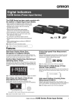
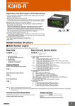
Digital Indicators
K3HB Series
Distinct by Design,
Distinguished in Performance
K3HB-H
K3HB-S
K3HB-X
K3HB-V
Features
Red-Green Display Allows Easy Recognition
of Judgment Results
Short Body with Depth of Only 95 mm (from
Behind the Front Panel)
• The measurement value display can be set to switch between red and green in accordance with the status of comparative outputs. This means that the status can be
ascertained at a distance.
• A short body of only 95 mm (see note) contributes to the development of slimmer and smaller control panels and installations.
Position Meter Enables Easy Monitoring of
Operating Status Trends
27%
shorter
than earlier
models
• The present value with respect to the measurement or display range (full scale) can be viewed on a bar display. The
operating status can be grasped intuitively, allowing easy
judgement of levels and threshold values.
Depth: 95 mm (See note.)
(The depth is 100 mm when mounted to the terminal cover.)
Note: Depth of DeviceNet models is 97 mm.
HH
H
P
L
Max
Min
B
L
LL
T-ZR CMW
Zero Hold
MAX/MIN
Select a Comparative Output Pattern to Suit
the Discrimination or Control Application
Position meter
TG
HH
H
T
LL
L
LEVEL
MODE
SHIFT
UP
Many Measurement and Discrimination
Functions Using External Event Input
• Offers a wide variety of application possibilities, such detection and judgement while synchronizing on an external signal.
• The output pattern for comparative outputs can be selected.
In addition to high/low comparison with set values, output
based on level changes is also possible. (Use the type of output pattern appropriate for the application.)
Comparative
set value HH
Comparative
set value H
Comparative
set value L
Comparative
set value LL
Standard Output
Output HH
Output PASS
Output PASS
Output L
Output L
Time
Sampling
measurement
TIMING ON
input OFF
Input
Peak hold value
Peak-to-peak value
(b2−a2)
(b1−a1)
Measurement value
b1
a1
'a2
Output LL
Zone Output
Lower
Output HH
ON
OFF
Output PASS
Bottom hold value
Time
TIMING OFF
input ON
Input
ON
OFF
Measurement
value
Higher
Output H
Measurement
value
Peak/bottom hold
measurement
Comparative
set value HH
Comparative
set value H
Comparative
set value L
Comparative
set value LL
Measurement
value
Higher
Lower
ON Output HH
OFF Output H
Output LL
Measurement value
Level Output
set value H
Comparative
set value L
Lower Comparative
set value LL
Output H
Sampling hold value
Input
Measurement
Comparative
value
set value HH
Higher Comparative
Peak-to-peak hold
measurement
'b2
Time
TIMING ON
input OFF
Output L
Output LL
Note: The HH, H, L, or LL outputs must be set in that order for the
zone outputs to output correctly.
(This is because the comparative set values and outputs for
standard and level outputs are in a 1-to-1 relationship, whereas
the meaning of zone outputs depends on the settings of all the
comparative set values.)
High-speed Sampling at 50 Times per Second
(20 ms)
Lineup Includes DeviceNet Models Enabling
High-speed Data Communications with PLCs
without Special Programming
• Provides an input sampling cycle at least three times faster
than earlier models (12.5 times faster for temperature input
models) at 50 times/second (see note). In addition to improved response times for judgement output and transfer
output, average processing can be used to increase the stability of measurements.
• DeviceNet compliance enables high-speed data transmission by allocating setting and monitoring parameters in the
I/O memory of the PLC. This capability greatly reduces labor
spent in developing communications programs.
Note: The K3HB-S Linear Sensor Indicator features high-speed response of 2,000 times/second.
Sampling at 15 times/second
Ethernet
DeviceNet
Master
Sampling at 50 times/second
Peak value
100
96
Timing of
internal
sampling
Time
Timing of
internal
sampling
0
P
H
Zero
K3HB
Digital Indicators
Time
P
Zero
2
Digital Indicators K3HB
Series (Analog Input Series)
DeviceNet
Configurator
Note: The applications provided in this catalog are intended as reference only. Do not attempt to use any of them in real systems without first confirming machine and device functions and safety. For applications that require safety, ensure that there is sufficient leeway in ratings and
performances, install fail-safe measures, and take any other safety measures required by the application. In addition, contact your nearest
OMRON representative and confirm specifications.
K3HB-series Product Lineup
■ K3HB-X Process Indicator (page 4)
Indicates Measurements for Voltage/Current Signals
• DC Voltage Input Type: K3HB-XVD
(±199.99 V, ±19.999 V, ±1.9999 V, 1.0000 to 5.0000 V)
• DC Current Input Type: K3HB-XAD
(±199.99 mA, ±19.999 mA, ±1.9999 mA, 4.000 to 20.000 mA)
• AC Voltage Input Type: K3HB-XVA
(0.0 to 400.0 V, 0.00 to 199.99 V, 0.000 to 19.999 V, 0.0000 to 1.9999 V)
• AC Current Input Type: K3HB-XAA
(0.000 to 10.000 A, 0.0000 to 1.9999 A, 0.00 to 199.99 mA, 0.000 to
19.999 mA)
■ K3HB-V Weighing Indicator (page 8)
Digital Indicators
K3HB Series (Analog Input Series)
3
Process Indicator
K3HB-X
A Process Indicator Ideal for Discriminating and
Displaying Measurements for Voltage/Current
Signals
• Easy recognition of judgement results using color display that can be
switched between red and green.
• Equipped with a position meter for monitoring operating status trends.
• External event input allows use in various measurement and discrimination applications.
• Series expanded to include DeviceNet models.
• Short body with depth of only 95 mm (from behind the front panel), or
97 mm for DeviceNet models.
• UL certification approval (Certification Mark License).
• CE Marking conformance by third party assessment body.
• Water-resistant enclosure conforms to NEMA 4X (equivalent to IP66).
• Capable of high-speed sampling at 50 times per second (20 ms)
• Easy-to-set two-point scaling allows conversion and display of any userset values.
Refer to Precautions on page 30.
Model Number Structure
■ Model Number Legend
Base Units and Optional Boards can be ordered individually or as sets.
Base Units
Base Units with Optional Boards
K3HB-X@-@@@
K3HB-X@
1
1
5
2 3 4
5
2. Sensor Power Supply/Output Type Codes
1. Input Sensor Codes
None: None
CPA: Relay output (PASS: SPDT) + Sensor power supply
(12 VDC +/−10%, 80 mA) (See note 1.)
L1A: Linear current output (DC0(4) − 20 mA) + Sensor power supply
(12 VDC +/−10%, 80 mA) (See note 2.)
L2A: Linear voltage output (DC0(1) − 5 V, 0 to 10 V) + Sensor power supply
(12 VDC +/−10%, 80 mA) (See note 2.)
A: Sensor power supply (12 VDC +/−10%, 80 mA)
FLK1A: Communications (RS-232C) + Sensor power supply
(12 VDC +/−10%, 80 mA) (See note 2.)
FLK3A: Communications (RS-485) + Sensor power supply
(12 VDC +/−10%, 80 mA) (See note 2.)
VD: DC voltage input
AD: DC current input
VA: AC voltage input
AA: AC current input
5. Supply Voltage
100-240 VAC: 100 to 240 VAC
24 VAC/VDC: 24 VAC/VDC
Optional Board
Sensor Power Supply/Output Boards
K33-@
2
Relay/Transistor Output Boards
K34-@
3
3. Relay/Transistor Output Type Codes
None: None
C1: Relay contact (H/L: SPDT each)
C2: Relay contact (HH/H/LL/L: SPST-NO each)
T1: Transistor (NPN open collector: HH/H/PASS/L/LL)
T2: Transistor (PNP open collector: HH/H/PASS/L/LL)
BCD: BCD output + transistor output (NPN open collector: HH/H/PASS/L/
LL)
DRT: DeviceNet (See note 2.)
4. Event input Type Codes
Event Input Boards
None: None
1: 5 points (M3 terminal blocks) NPN open collector
2: 8 points (10-pin MIL connector) NPN open collector
3: 5 points (M3 terminal blocks) PNP open collector
4: 8 points (10-pin MIL connector) PNP open collector
K35-@
4
Note: 1. CPA can be combined with relay outputs only.
2. Only one of the following can be used by each Digital Indicator:
RS-232C/RS-485 communications, a linear output, or DeviceNet communications.
Accessories (Sold Separately)
K32-DICN: Special Cable (for event inputs, with 8-pin connector)
K32-BCD: Special BCD Output Cable
4
Process Indicator
K3HB-X
Specifications
■ Ratings
Power supply voltage
100 to 240 VAC (50/60 Hz), 24 VAC/VDC, DeviceNet power supply: 24 VDC
Allowable power supply voltage range
85% to 110% of the rated power supply voltage, DeviceNet power supply: 11 to 25 VDC
Power consumption
(See note 1.)
100 to 240 V: 18 VA max. (max. load)
24 VAC/DC: 11 VA/7 W max. (max. load)
Current consumption
DeviceNet power supply: 50 mA max. (24 VDC)
Input
DC voltage, DC current, AC voltage, AC current
A/D conversion method
Delta-Sigma method
External power supply
See Sensor Power Supply/Output Type Codes
Event inputs (See
note 2.)
NPN open collector or no-voltage contact signal
ON residual voltage: 3 V max.
ON current at 0 Ω: 17 mA max.
Max. applied voltage: 30 VDC max.
OFF leakage current: 1.5 mA max.
Timing input
Startup compensa- NPN open collector or no-voltage contact signal
tion timer input
ON residual voltage: 2 V max.
ON current at 0 Ω: 4 mA max.
Hold input
Max. applied voltage: 30 VDC max.
Reset input
OFF leakage current: 0.1 mA max.
Forced-zero input
Bank input
Output ratings (de- Relay output
pends on the model)
Transistor output
Linear output
250 VAC, 30 VDC, 5 A (resistive load)
Mechanical life expectancy: 5,000,000 operations, Electrical life expectancy: 100,000 operations
Maximum load voltage: 24 VDC, Maximum load current: 50 mA, Leakage current: 100 µA max.
Linear output 0 to 20 mA DC, 4 to 20 mA:
Load: 500 Ω max, Resolution: Approx. 10,000, Output error: ±0.5% FS
Linear output 0 to 5 VDC, 1 to 5 VDC, 0 to 10 VDC:
Load: 5 kΩ max, Resolution: Approx. 10,000, Output error: ±0.5% FS
(1 V or less: ±0.15 V; not output for 0 V or less)
Display method
Negative LCD (backlit LED) display
7-segment digital display (Character height: PV: 14.2 mm (green/red); SV: 4.9 mm (green)
Main functions
Scaling function, measurement operation selection, averaging, previous average value comparison, forced-zero, zero-limit, output hysteresis, output OFF delay, output test, teaching, display value selection, display color
selection, key protection, bank selection, display refresh period, maximum/minimum hold, reset
Ambient operating temperature
−10 to 55°C (with no icing or condensation)
Ambient operating humidity
25% to 85%
Storage temperature
−25 to 65°C (with no icing or condensation)
Altitude
2,000 m max.
Accessories
Watertight packing, 2 fixtures, terminal cover, unit stickers, instruction manual. DeviceNet models also include
a DeviceNet connector (Hirose HR31-5.08P-5SC(01)) and crimp terminals (Hirose HR31-SC-121) (See note
3.)
Note: 1. DC power supply models require a control power supply capacity of approximately 1 A per Unit when power is turned ON. Particular
attention is required when using two or more DC power supply models. The OMRON S8VS-series DC Power Supply Unit is recommended.
2. PNP input types are also available.
3. For K3HB-series DeviceNet models, use only the DeviceNet Connector included with the product. The crimp terminals provided are for
Thin Cables.
Process Indicator
K3HB-X
5
■ Characteristics
Display range
−19,999 to 99,999
Sampling period
20 ms (50 times/second)
Comparative output response time DC input: 100 ms max.; AC input: 300 ms max.
Linear output response time
DC input: 150 ms max.; AC input: 420 ms max.
Insulation resistance
20 MΩ min. (at 500 VDC)
Dielectric strength
2,300 VAC for 1 min between external terminals and case
Noise immunity
100 to 240 VAC models:
±1,500 V at power supply terminals in normal or common mode
(waveform with 1-ns rising edge and pulse width of 1 µs/100 ns)
24 VAC/VDC models:
±1,500 V at power supply terminals in normal or common mode
(waveform with 1-ns rising edge and pulse width of 1 µs/100 ns)
Vibration resistance
Frequency: 10 to 55 Hz; Acceleration: 50 m/s2, 10 sweeps of 5 min each in X, Y, and Z directions
Shock resistance
150 m/s2 (100 m/s2 for relay outputs) 3 times each in 3 axes, 6 directions
Weight
Degree of
protection
Approx. 300 g (Base Unit only)
Front panel
Conforms to NEMA 4X for indoor use (equivalent to IP66)
Rear case
IP20
Terminals
IP00 + finger protection (VDE0106/100)
Memory protection
EEPROM (non-volatile memory)
Number of rewrites: 100,000
Applicable standards
UL61010C-1, CSA C22.2 No. 1010.1 (evaluated by UL)
EN61010-1 (IEC61010-1): Pollution degree 2/Overvoltage category II
EN61326: 1997, A1: 1998, A2: 2001
EMC
EMI: EN61326+A1 industrial applications
Electromagnetic radiation interference
CISPR 11 Group 1, Class A: CISPRL16-1/-2
Terminal interference voltage
CISPR 11 Group 1, Class A: CISPRL16-1/-2
EMS: EN61326+A1 industrial applications
Electrostatic Discharge Immunity
EN61000-4-2: 4 kV (contact), 8 kV (in air)
Radiated Electromagnetic Field Immunity
EN61000-4-3: 10 V/m 1 kHz sine wave amplitude modulation (80 MHz to 1 GHz)
Electrical Fast Transient/Burst Immunity
EN61000-4-4: 2 kV (power line), 1 kV (I/O signal line)
Surge Immunity
EN61000-4-5: 1 kV with line (power line), 2 kV with ground (power line)
Conducted Disturbance Immunity
EN61000-4-6: 3 V (0.15 to 80 MHz)
Voltage Dips and Interruptions Immunity
EN61000-4-11: 0.5 cycle, 0°/180°, 100% (rated voltage)
6
Process Indicator K3HB-X
■ Input Range (Measurement Range and Accuracy) CAT II
Input type
K3HB-XVD
DC voltage
K3HB-XAD
DC current
K3HB-XVA
AC voltage
(See note 4.)
K3HB-XAA
AC current
Range
Set value
Measurement range
Input
impedance
A
a Ud
±199.99 V
10 MΩ min.
B
b Ud
±19.999 V
1 MΩ min.
C
c Ud
±1.9999 V
D
d Ud
1.0000 to 5.0000 V
A
a ad
±199.99 mA
1 Ω max.
B
b ad
±19.999 mA
10 Ω max.
C
c ad
±1.9999 mA
33 Ω max.
D
d ad
4.000 to 20.000 mA
10 Ω max.
A
a Ua
0.0 to 400.0 V
1 MΩ min.
B
b Ua
0.00 to 199.99 V
C
c Ua
0.000 to 19.999 V
D
d Ua
0.0000 to 1.9999 V
A
a aa
0.000 to 10.000 A
(0.5 VA CT)
(See note 3.)
B
b aa
0.0000 to 1.9999 A
(0.5 VA CT)
(See note 3.)
C
c aa
0.00 to 199.99 mA
1 Ω max.
D
d aa
0.000 to 19.999 mA
10 Ω max.
Accuracy
Allowable
instantaneous
overload (30 s)
±0.1%rdg ± 1
digit max.
±400 V
±0.1%rdg ± 1
digit max.
±400 mA
±0.3%rdg ± 5
digits max.
700 V
±0.5%rdg ± 10
digits max.
400 V
±0.5%rdg ± 20
digits max.
20 A
±0.5%rdg ± 10
digits max.
2A
±200 V
±200 mA
Note: 1. The accuracy is for an input frequency range of 40 Hz to 1 kHz (except for AD current input A and B ranges) and an ambient temperature
of 23 ±5°C. The error, however, increases below 10% of the maximum input value.
DC voltage input (all ranges): 10% or less of max. input = ±0.15% FS
DC current input (all ranges): 10% or less of max. input = ±0.1% FS
AC voltage input (A: 0.0 to 400.0 V): 10% or less of max. input = ±0.15% FS
AC voltage input (B: 0.00 to 199.99 V): 10% or less of max. input = ±0.2% FS
AC voltage input (C: 0.000 to 19.999 V; D: 0.0000 to 1.9999 V): 10% or less of max. input = ±1.0% FS
AC current input (A: 0.000 to 10.000 A): 10% or less of max. input = ±0.25% FS
AC current input (B: 0.0000 to 1.9999 A): 10% or less of max. input = ±0.5% FS
AC current input, (C: 0.00 to 199.99 mA; D: 0.000 to 19.999 A): 10% or less of max. input = ±0.15% FS
When DC voltage input models are used with a ±1.9999 V range, make sure that the connections between input terminals are not open.
If the input terminals are open, the display will show large variations. Connect resistance of approximately 1 MΩ between the input terminals if they are open.
2. The letters “rdg” mean “reading” and refer to the input error.
3. The value (0.5 VA CT) is the VA consumption of the internal CT (current transformer).
E2
E3
±1.9999 V
E4
+
1 MΩ
−
E5
E6 COM
4. The K3HB-XVA@@ complies with UL standards when the applied input voltage is within the range 0 to 150 VAC.
If the input voltage is higher than 150 VAC, install an external transformer or take other measures to drop the voltage to 150 VAC or lower.
Process Indicator
K3HB-X
7
Weighing Indicator
K3HB-V
An Ideal Indicator for OK/NG Judgements in
Automated and Picking Machines, Measuring
Factors such as Pressure, Load, Torque, and
Weight Using Load Cell Signal Input.
• Easy recognition of judgement results using color display that can be
switched between red and green.
• Equipped with a position meter for monitoring operating status trends.
• External event input allows use in various measurement and discrimination applications.
• Series expanded to include DeviceNet models.
• Short body with depth of only 95 mm (from behind the front panel), or
97 mm for DeviceNet models.
• UL certification approval (Certification Mark License).
• CE Marking conformance by third party assessment body.
• Water-resistant enclosure conforms to NEMA 4X (equivalent to IP66).
• Capable of high-speed sampling at 50 times per second (20 ms)
• Easy-to-set two-point scaling allows conversion and display of any userset values.
Refer to Precautions on page 30.
Model Number Structure
■ Model Number Legend
Base Units and Optional Boards can be ordered individually or as sets.
Base Units
Base Units with Optional Boards
K3HB-V@
K3HB-V@-@@@
1
1
5
1. Input Sensor Codes
LC: Load cell input (DC low-voltage input)
5. Supply Voltage
100-240 VAC: 100 to 240 VAC
24 VAC/VDC: 24 VAC/VDC
Optional Board
Sensor Power Supply/Output Boards
2 3 4
None: None
CPB: Relay output (PASS: SPDT) + Sensor power supply
(10 VDC +/−5%, 100 mA) (See note 1.)
L1B: Linear current output (DC0(4) − 20 mA) + Sensor power supply
(10 VDC +/−5%, 100 mA) (See note 2.)
L2B: Linear voltage output (DC0(1) − 5 V, 0 to 10 V) + Sensor power supply
(10 VDC +/−5%, 100 mA) (See note 2.)
B: Sensor power supply (10 VDC +/−5%, 100 mA)
FLK1B: Communications (RS-232C) + Sensor power supply
(10 VDC +/−5%, 100 mA) (See note 2.)
FLK3B: Communications (RS-485) + Sensor power supply
(10 VDC +/−5%, 100 mA) (See note 2.)
3. Relay/Transistor Output Type Codes
None: None
C1: Relay contact (H/L: SPDT each)
C2: Relay contact (HH/H/LL/L: SPST-NO each)
T1: Transistor (NPN open collector: HH/H/PASS/L/LL)
T2: Transistor (PNP open collector: HH/H/PASS/L/LL)
BCD: BCD output + transistor output (NPN open collector: HH/H/PASS/L/
LL)
DRT: DeviceNet (See note 2.)
K33-@
2
Relay/Transistor Output Boards
K34-@
3
4. Event input Type Codes
Event Input Boards
None: None
1: 5 points (M3 terminal blocks) NPN open collector
2: 8 points (10-pin MIL connector) NPN open collector
3: 5 points (M3 terminal blocks) PNP open collector
4: 8 points (10-pin MIL connector) PNP open collector
K35-@
4
Note: 1. CPB can be combined with relay outputs only.
2. Only one of the following can be used by each Digital Indicator:
RS-232C/RS-485 communications, a linear output, or DeviceNet communications.
Accessories (Sold Separately)
K32-DICN: Special Cable (for event inputs, with 8-pin connector)
K32-BCD: Special BCD Output Cable
8
5
2. Sensor Power Supply/Output Type Codes
Weighing Indicator
K3HB-V
Specifications
■ Ratings
Power supply voltage
100 to 240 VAC (50/60 Hz), 24 VAC/VDC, DeviceNet power supply: 24 VDC
Allowable power supply voltage range
85% to 110% of the rated power supply voltage, DeviceNet power supply: 11 to 25 VDC
Power consumption
(See note 1.)
100 to 240 V: 18 VA max. (max. load)
24 VAC/DC: 11 VA/7 W max. (max. load)
Current consumption
DeviceNet power supply: 50 mA max. (24 VDC)
Input
DC voltage
A/D conversion method
Delta-Sigma method
External power supply
Event inputs
(See note 2.)
See Sensor Power Supply/Output Type Codes
Timing input
NPN open collector or no-voltage contact signal
ON residual voltage: 3 V max.
ON current at 0 Ω: 17 mA max.
Max. applied voltage: 30 VDC max.
OFF leakage current: 1.5 mA max.
Startup compensation
timer input
NPN open collector or no-voltage contact signal
ON residual voltage: 2 V max.
ON current at 0 Ω: 4 mA max.
Max. applied voltage: 30 VDC max.
OFF leakage current: 0.1 mA max.
Hold input
Reset input
Forced-zero input
Bank input
Output ratings (depends Relay output
on the model)
250 VAC, 30 VDC, 5 A (resistive load)
Mechanical life expectancy: 5,000,000 operations, Electrical life expectancy: 100,000 operations
Transistor output
Maximum load voltage: 24 VDC, Maximum load current: 50 mA, Leakage current: 100 µA max.
Linear output
Linear output 0 to 20 mA DC, 4 to 20 mA:
Load: 500 Ω max, Resolution: Approx. 10,000, Output error: ±0.5% FS
Linear output 0 to 5 VDC, 1 to 5 VDC, 0 to 10 VDC:
Load: 5 kΩ max, Resolution: Approx. 10,000, Output error: ±0.5% FS
(1 V or less: ±0.15 V; not output for 0 V or less)
Display method
Negative LCD (backlit LED) display
7-segment digital display (Character height: PV: 14.2 mm (green/red); SV: 4.9 mm (green)
Main functions
Scaling function, measurement operation selection, averaging, previous average value comparison, forcedzero, zero-limit, output hysteresis, output OFF delay, output test, teaching, display value selection, display
color selection, key protection, bank selection, display refresh period, maximum/minimum hold, reset
Ambient operating temperature
−10 to 55°C (with no icing or condensation)
Ambient operating humidity
25% to 85%
Storage temperature
−25 to 65°C (with no icing or condensation)
Altitude
2,000 m max.
Accessories
Watertight packing, 2 fixtures, terminal cover, unit stickers, operation manual. DeviceNet models also include
a DeviceNet connector (Hirose HR31-5.08P-5SC(01)) and crimp terminals (Hirose HR31-SC-121) (See note
3.)
Note: 1. DC power supply models require a control power supply capacity of approximately 1 A per Unit when power is turned ON. Particular
attention is required when using two or more DC power supply models. The OMRON S8VS-series DC Power Supply Unit is recommended.
2. PNP input types are also available.
3. For K3HB-series DeviceNet models, use only the DeviceNet Connector included with the product. The crimp terminals provided are for
Thin Cables.
Weighing Indicator
K3HB-V
9
■ Characteristics
Display range
−19,999 to 99,999
Sampling period
20 ms (50 times/second)
Comparative output response time 100 ms max.
Linear output response time
150 ms max.
Insulation resistance
20 MΩ min. (at 500 VDC)
Dielectric strength
2,300 VAC for 1 min between external terminals and case
Noise immunity
100 to 240 VAC models:
±1,500 V at power supply terminals in normal or common mode
(waveform with 1-ns rising edge and pulse width of 1 µs/100 ns)
24 VAC/VDC models:
±1,500 V at power supply terminals in normal or common mode
(waveform with 1-ns rising edge and pulse width of 1 µs/100 ns)
Vibration resistance
Frequency: 10 to 55 Hz; Acceleration: 50 m/s2, 10 sweeps of 5 min each in X, Y, and Z directions
Shock resistance
150 m/s2 (100 m/s2 for relay outputs) 3 times each in 3 axes, 6 directions
Weight
Degree of
protection
Approx. 300 g (Base Unit only)
Front panel
Conforms to NEMA 4X for indoor use (equivalent to IP66)
Rear case
IP20
Terminals
IP00 + finger protection (VDE0106/100)
Memory protection
EEPROM (non-volatile memory)
Number of rewrites: 100,000
Applicable standards
UL61010C-1, CSA C22.2 No. 1010.1 (evaluated by UL)
EN61010-1 (IEC61010-1): Pollution degree 2/Overvoltage category II
EN61326: 1997, A1: 1998, A2: 2001
EMC
EMI: EN61326+A1 industrial applications
Electromagnetic radiation interference
CISPR 11 Group 1, Class A: CISPRL16-1/-2
Terminal interference voltage
CISPR 11 Group 1, Class A: CISPRL16-1/-2
EMS: EN61326+A1 industrial applications
Electrostatic Discharge Immunity
EN61000-4-2: 4 kV (contact), 8 kV (in air)
Radiated Electromagnetic Field Immunity
EN61000-4-3: 10 V/m 1 kHz sine wave amplitude modulation (80 MHz to 1 GHz)
Electrical Fast Transient/Burst Immunity
EN61000-4-4: 2 kV (power line), 1 kV (I/O signal line)
Surge Immunity
EN61000-4-5: 1 kV with line (power line), 2 kV with ground (power line)
Conducted Disturbance Immunity
EN61000-4-6: 3 V (0.15 to 80 MHz)
Voltage Dips and Interruptions Immunity
EN61000-4-11: 0.5 cycle, 0°/180°, 100% (rated voltage)
10
Weighing Indicator K3HB-V
■ Input Ranges (Measurement Range and Accuracy)
Input type
Range
K3HB-VLC
Load Cell, mV
Set value
Measurement range
Input impedance
1 MΩ min.
Accuracy
A
a Ud
0.00 to 199.99 mV
B
b Ud
0.000 to 19.999 mV
±0.1%rdg ± 5 digits max.
C
c Ud
±100.00 mV
±0.1%rdg ± 3 digits max.
D
d Ud
±199.99 mV
±0.1%rdg ± 1 digit max.
±0.1%rdg ± 1 digit max.
Allowable
instantaneous
overload (30 s)
±200 V
Note: 1. The accuracy is for an ambient temperature of 23±5°C. For all ranges,10% or less of max. input ±0.1% FS.
2. The letters “rdg” mean “reading.”
Input type
Connected
terminals
(mV)
200.000
a lc
E2
b lc
E6
E3
E6
E4
E6
199.99
d lc
E5
E6
199.99
150.000
100.000
50.000
0.00
−50.00
−100.00
−150.00
−200.00
c lc
100.00
19.999
0.00
0.000
−100.00
−199.99
The area shown in dark shading indicates the factory setting.
■ Load Cell Wiring Example
B
E
■ Scaling Example Using Range A
Indicated on the K3HB-V as 0 to 49N in the load cell specifications
(rated load 49N, recommended applied voltage 10 V, rated output 2
mV/V) (See note.)
+10 V
Display value
+IN
E2
Scaling values:
49 N
E3
E4
B5
E5
B6
E6
+OUT
Load cell
inp.a1=000.00
dsp.a1=00000
inp.a2=020.00
dsp.a2=49000
dp decimal point position: 00.000
−OUT
+
−IN
20 mV
−
0V
Input value
Note: 2 mV/V indicates a load cell output of 2 mV for 1 V applied voltage for the rated load (when using a load of 1 N). When the applied voltage is 10 V, the load cell output is 20 mV (2 mV × 10).
Weighing Indicator
K3HB-V
11
Temperature Indicator
K3HB-H
New High-speed, High-precision Temperature
Indicator
• Easy recognition of judgement results using color display that can be
switched between red and green.
• Equipped with a position meter for monitoring operating status trends.
• External event input allows use in various measurement and discrimination applications.
• Series expanded to include DeviceNet models.
• Short body with depth of only 95 mm (from behind the front panel), or
97 mm for DeviceNet models.
• UL certification approval (Certification Mark License).
• CE Marking conformance by third party assessment body.
• Water-resistant enclosure conforms to NEMA 4X (equivalent to IP66).
• Capable of high-speed sampling at 50 times per second (20 ms).
• High-resolution of 0.01°C with platinum-resistance thermometer Pt100
input. Thermocouple sensor inputs also support a resolution of 0.1°C
for all ranges.
• Temperature input shift is easily set using two points.
Refer to Precautions on page 30.
Model Number Structure
■ Model Number Legend
Base Units and Optional Boards can be ordered individually or as sets.
Base Units
Base Units with Optional Boards
K3HB-H@-@@@
K3HB-H@
1
1
5
1. Input Sensor Codes
2 3 4
5
2. Sensor Power Supply/Output Type Codes
TA: Temperature input
Thermocouple input/Platinum-resistance thermometer input
5. Supply Voltage
100-240 VAC: 100 to 240 VAC
24 VAC/VDC: 24 VAC/VDC
None: None
CPA:
Relay output (PASS: SPDT) + Sensor power supply
(12 VDC +/−10%, 80 mA) (See note 1.)
L1A:
Linear current output (DC0(4) − 20 mA) + Sensor power supply
(12 VDC +/−10%, 80 mA) (See note 2.)
L2A:
Linear voltage output (DC0(1) − 5 V, 0 to 10 V) + Sensor power supply
(12 VDC +/−10%, 80 mA) (See note 2.)
A:
Sensor power supply (12 VDC +/−10%, 80 mA)
FLK1A: Communications (RS-232C) + Sensor power supply
(12 VDC +/−10%, 80 mA) (See note 2.)
FLK3A: Communications (RS-485) + Sensor power supply
(12 VDC +/−10%, 80 mA) (See note 2.)
Optional Board
Sensor Power Supply/Output Boards
3. Relay/Transistor Output Type Codes
None:
C1:
C2:
T1:
T2:
BCD:
K33-@
2
Relay/Transistor Output Boards
K34-@
3
DRT:
Event Input Boards
None
Relay contact (H/L: SPDT each)
Relay contact (HH/H/LL/L: SPST-NO each)
Transistor (NPN open collector: HH/H/PASS/L/LL)
Transistor (PNP open collector: HH/H/PASS/L/LL)
BCD output + transistor output (NPN open collector: HH/H/PASS/
L/LL)
DeviceNet (See note 2.)
4. Event input Type Codes
None:
1:
2:
3:
4:
K35-@
4
None
5 points (M3 terminal blocks) NPN open collector
8 points (10-pin MIL connector) NPN open collector
5 points (M3 terminal blocks) PNP open collector
8 points (10-pin MIL connector) PNP open collector
Note: 1. CPA can be combined with relay outputs only.
2. Only one of the following can be used by each Digital Indicator:
RS-232C/RS-485 communications, a linear output, or DeviceNet communications.
Accessories (Sold Separately)
K32-DICN: Special Cable (for event inputs, with 8-pin connector)
K32-BCD: Special BCD Output Cable
12
Temperature Indicator
K3HB-H
Specifications
■ Ratings
Power supply voltage
100 to 240 VAC (50/60 Hz), 24 VAC/VDC, DeviceNet power supply: 24 VDC
Allowable power supply voltage range
85% to 110% of the rated power supply voltage, DeviceNet power supply: 11 to 25 VDC
Power consumption
(See note 1.)
100 to 240 V: 18 VA max. (max. load)
24 VAC/DC: 11 VA/7 W max. (max. load)
Current consumption
DeviceNet power supply: 50 mA max. (24 VDC)
Input
Platinum-resistance thermometer: Pt100
Thermocouple: K, J, T, E, L, U, N, R, S, B, W
A/D conversion method
Delta-Sigma method
External power supply
See Sensor Power Supply/Output Type Codes
Event inputs
(See note 2.)
NPN open collector or no-voltage contact signal
ON residual voltage: 3 V max.
ON current at 0 Ω: 17 mA max.
Max. applied voltage: 30 VDC max.
OFF leakage current: 1.5 mA max.
Timing input
Startup compensa- NPN open collector or no-voltage contact signal
tion timer input
ON residual voltage: 2 V max.
ON current at 0 Ω: 4 mA max.
Hold input
Max. applied voltage: 30 VDC max.
OFF leakage current: 0.1 mA max.
Reset input
Bank input
Output ratings
(depends on the
model)
Relay output
250 VAC, 30 VDC, 5 A (resistive load)
Mechanical life expectancy: 5,000,000 operations, Electrical life expectancy: 100,000 operations
Transistor output
Maximum load voltage: 24 VDC, Maximum load current: 50 mA, Leakage current: 100 µA max.
Linear output
Linear output 0 to 20 mA DC, 4 to 20 mA:
Load: 500 Ω max, Resolution: Approx. 10,000, Output error: ±0.5% FS
Linear output 0 to 5 VDC, 1 to 5 VDC, 0 to 10 VDC:
Load: 5 kΩ max, Resolution: Approx. 10,000, Output error: ±0.5% FS
(1 V or less: ±0.15 V; not output for 0 V or less)
Display method
Negative LCD (backlit LED) display
7-segment digital display (Character height: PV: 14.2 mm (green/red); SV: 4.9 mm (green)
Main functions
Scaling function, measurement operation selection, averaging, previous average value comparison, zero-limit,
output hysteresis, output OFF delay, output test, display value selection, display color selection, key protection,
bank selection, display refresh period, maximum/minimum hold, reset
Ambient operating temperature
−
Note: 1. DC power supply models require a control power supply capacity of approximately 1 A per Unit when power is turned ON. Particular attention is
required when using two or more DC power supply models. The OMRON S8VS-series DC Power Supply Unit is recommended.
2. PNP input types are also available.
3. For K3HB-series DeviceNet models, use only the DeviceNet Connector included with the product. The crimp terminals provided are for Thin Cables.
Temperature Indicator
K3HB-H
13
■ Characteristics
Display range
−19,999 to 99,999
Accuracy
Thermocouple input: (±0.3% PV or ±1°C, whichever is larger) ± 1 digit max. (See note.)
Platinum resistance thermometer input: (±0.2% PV or ±0.8°C, whichever is larger) ± 1 digit max.
Sampling period
20 ms (50 times/second)
Comparative output response time Platinum-resistance thermometer input range: 120 ms max.
Thermocouple input range: 180 ms max.
Linear output response time
Platinum-resistance thermometer input range: 170 ms max.
Thermocouple input range: 230 ms max.
Insulation resistance
20 MΩ min. (at 500 VDC)
Dielectric strength
2,300 VAC for 1 min between external terminals and case
Noise immunity
100 to 240 VAC models:
±1,500 V at power supply terminals in normal or common mode
(waveform with 1-ns rising edge and pulse width of 1 µs/100 ns)
24 VAC/VDC models:
±1,500 V at power supply terminals in normal or common mode
(waveform with 1-ns rising edge and pulse width of 1 µs/100 ns)
Vibration resistance
Frequency: 10 to 55 Hz; Acceleration: 50 m/s2, 10 sweeps of 5 min each in X, Y, and Z directions
Shock resistance
150 m/s2 (100 m/s2 for relay outputs) 3 times each in 3 axes, 6 directions
Weight
Approx. 300 g (Base Unit only)
Degree of pro- Front panel
tection
Rear case
Conforms to NEMA 4X for indoor use (equivalent to IP66)
Terminals
IP20
IP00 + finger protection (VDE0106/100)
Memory protection
EEPROM (non-volatile memory)
Number of rewrites: 100,000
Applicable standards
UL61010C-1, CSA C22.2 No. 1010.1 (evaluated by UL)
EN61010-1 (IEC61010-1): Pollution degree 2/Overvoltage category II
EN61326: 1997, A1: 1998, A2: 2001
EMC
EMI: EN61326+A1 industrial applications
Electromagnetic radiation interference
CISPR 11 Group 1, Class A: CISPRL16-1/-2
Terminal interference voltage
CISPR 11 Group 1, Class A: CISPRL16-1/-2
EMS: EN61326+A1 industrial applications
Electrostatic Discharge Immunity
EN61000-4-2: 4 kV (contact), 8 kV (in air)
Radiated Electromagnetic Field Immunity
EN61000-4-3: 10 V/m 1 kHz sine wave amplitude modulation (80 MHz to 1 GHz)
Electrical Fast Transient/Burst Immunity
EN61000-4-4: 2 kV (power line), 1 kV (I/O signal line)
Surge Immunity
EN61000-4-5: 1 kV with line (power line), 2 kV with ground (power line)
Conducted Disturbance Immunity
EN61000-4-6: 3 V (0.15 to 80 MHz)
Voltage Dips and Interruptions Immunity
EN61000-4-11: 0.5 cycle, 0°/180°, 100% (rated voltage)
Note: K, T, N (–100°C or less): ±2°C ±1 digit max.
U, L: ±2°C ±1 digit max.
B (400°C max.): Nothing specified.
R, S (200°C max.): ±3°C ±1 digit max.
W: (±0.3% PV or ±3°C whichever is larger) ±1 digit max.
14
Temperature Indicator K3HB-H
■ Input Ranges
Platinum-resistance Thermometer/Thermocouple
Input type
Platinumresistance
thermometer
Name
Pt100
Connected
terminals
Temperature
range
(°C)
Thermocouple
E4
E5
K
J
T
E
L
E6
E5
U
N
B
W
(W/Re
5-26)
2300.0
1700.0 1700.0 1800.0
1800
900
S
E6
2300
1300
R
1300.0
1300.0
850.0
850.0
850.0
800
700
500.0
600
600.0
400.0
400
400.0
400.0
150.00
200
100
100.0
0
0.0
−100
−200
−20.0 −100.0
−20.0
−200.0 −150.00 −200.0
Setting code
0-pt
1-pt
Minimum
setting unit
(comparative
set value)
0.1°C 0.01°C
2-k
4-j
0.0
11-r
12-s
0.0
−100.0
−200.0
3-k
0.0
5-j
6-t
−200.0 −200.0
7-e
8-l
9-u
10-n
13-b
14-w
0.1°C
The range shown in dark shading indicates the factory setting.
Celsius/Fahrenheit Correlation Values and Setting/Specified Ranges
Input type
Setting range
Indication range
°C
°F
°C
°F
Pt100 (1)
−200.0 to 850.0
−300.0 to 1500.0
−305.0 to 955.0
−480.0 to 1680.0
Pt100 (2)
−150.00 to 150.00
−199.99 to 300.00
−180.00 to 180.00
−199.99 to 350.00
K (1)
−200.0 to 1300.0
−300.0 to 2300.0
−350.0 to 1450.0
−560.0 to 2560.0
K (2)
−20.0 to 500.0
0.0 to 900.0
−72.0 to 552.0
−90.0 to 990.0
J (1)
−100.0 to 850.0
−100.0 to 1500.0
−195.0 to 945.0
−260.0 to 1660.0
J (2)
−20.0 to 400.0
0.0 to 750.0
−62.0 to 442.0
−75.0 to 825.0
T
−200.0 to 400.0
−300.0 to 700.0
−260.0 to 460.0
−400.0 to 800.0
E
0.0 to 600.0
0.0 to 1100.0
−60.0 to 660.0
−110.0 to 1210.0
L
−100.0 to 850.0
−100.0 to 1500.0
−195.0 to 945.0
−260.0 to 1660.0
U
−200.0 to 400.0
−300.0 to 700.0
−260.0 to 460.0
−400.0 to 800.0
N
−200.0 to 1300.0
−300.0 to 2300.0
−350.0 to 1450.0
−560.0 to 2560.0
R
0.0 to 1700.0
0.0 to 3000.0
−170.0 to 1870.0
−300.0 to 3300.0
S
0.0 to 1700.0
0.0 to 3000.0
−170.0 to 1870.0
−300.0 to 3300.0
B
100.0 to 1800.0
300.0 to 3200.0
−70.0 to 1970.0
10.0 to 3490.0
W
0.0 to 2300.0
0.0 to 4100.0
−230.0 to 2530.0
−410.0 to 4510.0
Temperature Indicator
K3HB-H
15
Linear Sensor Indicator
K3HB-S
A Linear Sensor Indicator Capable of High-speed
Response at 2,000 Times per Second
• Effective for high-speed measurement and discrimination with a sampling period of 0.5 ms and output response time of 1 ms max.
• Easy recognition of judgement results using color display that can be
switched between red and green.
• Equipped with a position meter that represents measured amounts and
relative positions.
• Zero calibration can be performed easily with the forced zero function.
• Series expanded to include DeviceNet models.
• Short body with depth of only 95 mm (from behind the front panel), or
97 mm for DeviceNet models.
• UL certification approval (Certification Mark License).
• CE Marking conformance by third party assessment body.
• Water-resistant enclosure conforms to NEMA 4X (equivalent to IP66).
Refer to Precautions on page 30.
Model Number Structure
■ Model Number Legend
Base Units and Optional Boards can be ordered individually or as sets.
Base Units
Base Units with Optional Boards
K3HB-S@-@@@
K3HB-S@
1
1
5
2 3 4
5
2. Sensor Power Supply/Output Type Codes
1. Input Sensor Codes
None: None
CPA: Relay output (PASS: SPDT) + Sensor power supply
(12 VDC +/−10%, 80 mA) (See note 1.)
L1A: Linear current output (DC0(4) − 20 mA) + Sensor power supply
(12 VDC +/−10%, 80 mA) (See note 2.)
L2A: Linear voltage output (DC0(1) − 5 V, 0 to 10 V) + Sensor power supply
(12 VDC +/−10%, 80 mA) (See note 2.)
A: Sensor power supply (12 VDC +/−10%, 80 mA)
FLK1A: Communications (RS-232C) + Sensor power supply
(12 VDC +/−10%, 80 mA) (See note 2.)
FLK3A: Communications (RS-485) + Sensor power supply
(12 VDC +/−10%, 80 mA) (See note 2.)
SD: DC Process input
5. Supply Voltage
100-240 VAC: 100 to 240 VAC
24 VAC/VDC: 24 VAC/VDC
Optional Board
Sensor Power Supply/Output Boards
3. Relay/Transistor Output Type Codes
None: None
C1: Relay contact (H/L: SPDT each)
C2: Relay contact (HH/H/LL/L: SPST-NO each)
T1: Transistor (NPN open collector: HH/H/PASS/L/LL)
T2: Transistor (PNP open collector: HH/H/PASS/L/LL)
BCD: BCD output + transistor output (NPN open collector: HH/H/PASS/L/
LL)
DRT: DeviceNet (See note 2.)
K33-@
2
Relay/Transistor Output Boards
K34-@
3
4. Event input Type Codes
None: None
1: 5 points (M3 terminal blocks) NPN open collector
2: 8 points (10-pin MIL connector) NPN open collector
3: 5 points (M3 terminal blocks) PNP open collector
4: 8 points (10-pin MIL connector) PNP open collector
Event Input Boards
K35-@
4
Note: 1. CPA can be combined with relay outputs only.
2. Only one of the following can be used by each Digital Indicator:
RS-232C/RS-485 communications, a linear output, or DeviceNet communications.
Accessories (Sold Separately)
K32-DICN: Special Cable (for event inputs, with 8-pin connector)
K32-BCD: Special BCD Output Cable
16
Linear Sensor Indicator
K3HB-S
Specifications
■ Ratings
Power supply voltage
100 to 240 VAC (50/60 Hz), 24 VAC/VDC, DeviceNet power supply: 24 VDC
Allowable power supply voltage range
85% to 110% of the rated power supply voltage, DeviceNet power supply: 11 to 25 VDC
Power consumption
(See note 1.)
100 to 240 V: 18 VA max. (max. load)
24 VAC/DC: 11 VA/7 W max. (max. load)
Current consumption
DeviceNet power supply: 50 mA max. (24 VDC)
Input
DC voltage/current
A/D conversion method
Sequential comparison system
External power supply
See Sensor Power Supply/Output Type Codes
Event inputs
(See note 2.)
Timing input
NPN open collector or no-voltage contact signal
ON residual voltage: 3 V max.
ON current at 0 Ω: 17 mA max.
Max. applied voltage: 30 VDC max.
OFF leakage current: 1.5 mA max.
Startup compensation timer input
NPN open collector or no-voltage contact signal
ON residual voltage: 2 V max.
ON current at 0 Ω: 4 mA max.
Max. applied voltage: 30 VDC max.
OFF leakage current: 0.1 mA max.
Hold input
Reset input
Forced-zero input
Bank input
Output ratings (deRelay output
pends on the model)
250 VAC, 30 VDC, 5 A (resistive load)
Mechanical life expectancy: 5,000,000 operations, Electrical life expectancy: 100,000 operations
Transistor output
Maximum load voltage: 24 VDC, Maximum load current: 50 mA, Leakage current: 100 µA max.
Linear output
Linear output 0 to 20 mA DC, 4 to 20 mA:
Load: 500 Ω max, Resolution: Approx. 10,000, Output error: ±0.5% FS
Linear output 0 to 5 VDC, 1 to 5 VDC, 0 to 10 VDC:
Load: 5 kΩ max, Resolution: Approx. 10,000, Output error: ±0.5% FS
(1 V or less: ±0.15 V; not output for 0 V or less)
Display method
Negative LCD (backlit LED) display
7-segment digital display (Character height: PV: 14.2 mm (green/red); SV: 4.9 mm (green)
Main functions
Scaling function, 2-input calculation function, measurement operation selection, averaging, previous average value
comparison, forced-zero, zero-limit, output hysteresis, output OFF delay, output test, teaching, display value selection,
display
color
selection,
key
protection,
Ambient operating temperature
−10 to 55°C (with no icing or condensation)
Ambient operating humidity
25% to 85%
Storage temperature
−25 to 65°C (with no icing or condensation)
Altitude
Note: 1. DC power supply models require a control power supply capacity of approximately 1 A per Unit when power is turned ON. Particular
attention is required when using two or more DC power supply models. The OMRON S8VS-series DC Power Supply Unit is recommended.
2. PNP input types are also available.
3. For K3HB-series DeviceNet models, use only the DeviceNet Connector included with the product. The crimp terminals provided are for
Thin Cables.
Linear Sensor Indicator
K3HB-S
17
■ Characteristics
−19,999 to 99,999
Display range
Sampling period
One input: 0.5 ms; Two inputs: 1.0 ms
Comparative out- One input
put response
times (transistor Two inputs
outputs)
OFF to ON: 1 ms max., ON to OFF: 1.5 ms max.
Linear output re- One input
sponse time
Two inputs
51 ms max.
OFF to ON: 2 ms max., ON to OFF: 2.5 ms max.
52 ms max.
Insulation resistance
20 MΩ min. (at 500 VDC)
Dielectric strength
2,300 VAC for 1 min between external terminals and case
Noise immunity
100 to 240 VAC models:
±1,500 V at power supply terminals in normal or common mode
(waveform with 1-ns rising edge and pulse width of 1 µs/100 ns)
24 VAC/VDC models:
±1,500 V at power supply terminals in normal or common mode
(waveform with 1-ns rising edge and pulse width of 1 µs/100 ns)
Vibration resistance
Frequency: 10 to 55 Hz; Acceleration: 50 m/s2, 10 sweeps of 5 min each in X, Y, and Z directions
Shock resistance
150 m/s2 (100 m/s2 for relay outputs) 3 times each in 3 axes, 6 directions
Weight
Approx. 300 g (Base Unit only)
Degree of protec- Front panel
tion
Rear case
Conforms to NEMA 4X for indoor use (equivalent to IP66)
Terminals
IP20
IP00 + finger protection (VDE0106/100)
Memory protection
EEPROM (non-volatile memory)
Number of rewrites: 100,000
Applicable standards
UL61010C-1, CSA C22.2 No. 1010.1(evaluated by UL)
EN61010-1 (IEC61010-1): Pollution degree 2/Overvoltage category II
EN61326: 1997, A1: 1998, A2: 2001
EMC
EMI: EN61326+A1 industrial applications
Electromagnetic radiation interference
CISPR 11 Group 1, Class A: CISPRL16-1/-2
Terminal interference voltage
CISPR 11 Group 1, Class A: CISPRL16-1/-2
EMS: EN61326+A1 industrial applications
Electrostatic Discharge Immunity
EN61000-4-2: 4 kV (contact), 8 kV (in air)
Radiated Electromagnetic Field Immunity
EN61000-4-3: 10 V/m 1 kHz sine wave amplitude modulation (80 MHz to 1 GHz)
Electrical Fast Transient/Burst Immunity
EN61000-4-4: 2 kV (power line), 1 kV (I/O signal line)
Surge Immunity
EN61000-4-5: 1 kV with line (power line), 2 kV with ground (power line)
Conducted Disturbance Immunity
EN61000-4-6: 3 V (0.15 to 80 MHz)
Voltage Dips and Interruptions Immunity
EN61000-4-11: 0.5 cycle, 0°/180°, 100% (rated voltage)
■ Input Ranges (Measurement Ranges and Accuracy)
Input
Input type
K3HB-SSD
DC voltage/current
input
Measurement range
0 to 20 mA
0.000 to 20.000 mA
−2.000 to 22.000 mA
4 to 20 mA
4.000 to 20.000 mA
2.000 to 22.000 mA
0 to 5 V
0.000 to 5.000 V
−0.500 to 5.500 mA
1 to 5 V
1.000 to 5.000 V
0.500 to 5.500 V
±5 V
±5.000 V
± 5.500 V
±10 V
±10.000 V
± 11.000 V
Note: The accuracy is for an ambient temperature of 23±5°C.
18
Indication range
Linear Sensor Indicator K3HB-S
Input
impedance
120 Ω max.
1 MΩ min.
Accuracy
(at 23±5°C)
One input:
Maximum
absolute rated
input
±31 mA
±0.1% F.S.
±1 digit max.
Two inputs:
±0.2% F.S.
±1 digit max.
±10 V
±14.5 V
Input type
DC current input
0-20
Connected terminals
Input A
in-ta
Input B
in-tb
DC current
range (mA)
E2
E3
E1
E3
22.000
24.000
Input type
4-20
Connected terminals
22.000
DC voltage input
0-5
1-5
5
Input A
in-ta
E4
E3
Input B
in-tb
E5
E3
10
DC voltage
range (V)
11.000
20.000
16.000
10.000
12.000
5.000
8.000
0.000
4.000
−5.000
0.000
5.500
−0.500
0.500
5.500
−5.500
−10.000
2.000
−4.000
5.500
−11.000
−2.000
The range shown in dark shading indicates the factory setting.
Sampling and Comparative Output Response Times
The K3HB-S sampling and comparative output response times depend on the calculation methods, timing hold type, and, for simple averaging, the
averaging times. Refer to the following description for details.
■ Output Refresh Period
■ Output Response Time
The K3HB-S repeats input reads, calculation, and judgement output
processing. The output refresh period differs depending on whether
there are one or two inputs, as outlined below.
The comparative output response time is the sum of the data processing time and the output (relay or transistor) response time.
One Input
One Input
0.5 ms
0.5 ms
0.5 ms
0.5 ms
0.5 ms
0.5 ms
Data processing time
Input A
or
Input B
Input
↓
Input
↓
Input
↓
Input
↓
Input
↓
Input
↓
↓
Output
↓
Output
↓
Output
↓
Output
↓
Output
Input read
Every 0.5 ms
Output
refresh
Every 0.5 ms
R
R
R
R
Two Inputs
0.5 ms
0.5 ms
0.5 ms
0.5 ms
Two inputs
Input A
or
Input B
Data processing time
0.5 ms
0.5 ms
Input
Input
↓
Output
Input read
Output response time
(See note.)
0.5 ms
Input
↓
↓
Output
Input A: Every 1 ms
R
Input
Output
Input
↓
↓
Output
Input
Output
Input
↓
↓
Output
R
R
R
R
Output response time
(See note.)
Note: For transistor outputs:
For one input: OFF to ON 1 ms and ON to OFF 1.5 ms
For two inputs: OFF to ON 2 ms and ON to OFF 2.5 ms
For relay outputs:
The relay operation time of 15 ms is added to the transistor
output response times.
Input B: Every 1 ms
Output
refresh
Every 0.5 ms
Linear Sensor Indicator
K3HB-S
19
Common Specifications
■ Event Input Ratings
Input type
S-TMR, HOLD, RESET, ZERO, BANK1, BANK2,
BANK4
TIMING
Contact
ON: 1 kΩ max., OFF: 100 kΩ min.
---
No-contact
ON residual voltage: 2 V max.
OFF leakage current: 0.1 mA max.
Load current: 4 mA max.
Maximum applied voltage: 30 VDC max.
ON residual voltage: 3 V max.
OFF leakage current: 1.5 mA max.
Load current: 17 mA max.
Maximum applied voltage: 30 VDC max.
■ Output Ratings
Contact Output
Item
Transistor Output
Inductive loads
(250 VAC, closed
circuit, cosφ=0.4;
30 VDC, L/R=7 ms)
Resistive loads
(250 VAC, cosφ=1;
30 VDC, L/R=0 ms)
Rated load
5 A at 250 VAC
5 A at 30 VDC
Rated through
current
5A
Maximum load voltage
24 VDC
Maximum load current
50 mA
Leakage current
100 µA max.
1 A at 250 VAC
1 A at 30 VDC
Mechanical life 5,000,000 operations
expectancy
Electrical life
expectancy
100,000 operations
Linear Output
Item
0 to 20 mA
Allowable load impedance
500 Ω max.
Resolution
Approx. 10,000
Output error
±0.5%FS
4 to 20 mA
Serial Communications Output
Item
RS-232C, RS-485
Start-stop synchronization
Baud rate
9,600, 19,200, or 38,400 bps
Transmission code
ASCII
Data length
7 bits or 8 bits
Stop bit length
2 bits or 1 bit
Error detection
Vertical parity and FCS
Parity check
Odd, even
Note: For details on serial and DeviceNet communications, refer to
the Digital Indicator K3HB Communications User's Manual
(Cat.No. N129).
1 to 5 V
0 to 10 V
BCD Output I/O Ratings
(Input Signal Logic: Negative)
Communications method Half duplex
Synchronization method
0 to 5 V
5 kΩ min.
I/O signal name
Inputs
REQUEST
HOLD
MAX
MIN
RESET
Outputs DATA
POLARITY
OVER
DATA VALID
RUN
HH
H
PASS
L
LL
Item
Rating
Input signal
No-voltage
contact input
Input current for
no-voltage input
10 mA
Signal ON voltage 1.5 V max.
level
OFF voltage 3 V min.
Maximum load
voltage
Maximum load
current
Leakage current
Maximum load
voltage
Maximum load
current
Leakage current
24 VDC
10 mA
100 µA max.
24 VDC
50 mA
100 µA max.
Note: For details on serial and DeviceNet communications, refer to
the Digital Indicator K3HB Communications User's Manual
(Cat.No. N129).
20
Digital Indicators K3HB-X/-V/-H/-S
DeviceNet Communications
Communications protocol
Conforms to DeviceNet
Supported communi- Remote I/O communications
cations
Master-Slave connection (polling, bit-strobe, COS, cyclic)
Conforms to DeviceNet communications standards.
I/O allocations
Allocate any I/O data using the Configurator.
Allocate any data, such as DeviceNet-specific parameters and variable area for Digital
Indicators.
Input area: 2 blocks, 60 words max.
Output area: 1 block, 29 words max.
(The first word in the area is always allocated for the Output Execution Enabled Flags.)
Message communications
Explicit message communications
CompoWay/F communications commands can be executed (using explicit message
communications)
Connection methods
Combination of multi-drop and T-branch connections (for trunk and drop lines)
Baud rate
DeviceNet: 500, 250, or 125 Kbps (automatic follow-up)
Communications media
Special 5-wire cable (2 signal lines, 2 power supply lines, 1 shield line)
Communications distance
Baud rate
Network length
(max.)
Drop line length
(max.)
Total drop line
length (max.)
500 Kbps
100 m (100 m)
6m
39 m
250 Kbps
100 m
(250 m)
6m
78 m
125 Kbps
100 m
(500 m)
6m
156 m
The values in parentheses are for Thick Cable.
Communications power supply
24-VDC DeviceNet power supply
Allowable voltage fluctuation range
11 to 25-VDC DeviceNet power supply
Current consumption
50 mA max. (24 VDC)
Maximum number of nodes
64 (DeviceNet Configurator is counted as one node when connected)
Maximum number of slaves
63
Error control checks
CRC errors
DeviceNet power supply
Supplied from DeviceNet communications connector
■ Internal Block Diagram
Analog input
Input
circuit
ADC
Keys
EEP-ROM
Indications
• Input circuit
• Output circuit
• Transistor
output circuit
Drive
circuit
Drive
circuit
Event input
Digital input
circuit
Waveform
shaping circuit
Linear output
Linear output
circuit
Drive
circuit
Sensor power
supply
Filter
BCD
BCD I/O
Microcomputer
Drive
circuit
Transistor
output
Relay output
X
Drive
circuit
DeviceNet
circuit
DeviceNet
Drive
circuit
Communications
driver
Communications
VCOM
VDD
VO
Power supply circuit (isolated)
VO
DC-DC
Converter (isolated)
Power supply
Digital Indicators
K3HB-X/-V/-H/-S
21
■ Power Supply Derating Curve for Sensor (Reference Value)
With 12 V
With 10 V
Max. current (mA)
140
Max. current (mA)
140
1
1
120
120
100
100
80
80
60
60
40
40
20
20
0
−20
−10
0
10
20
30
40
50
0
−20
60
−10
0
10
20
30
40
50
60
Ambient temperature (°C)
Ambient temperature (°C)
Note: 1. The above values are for standard mounting. The derating curve differs depending on the mounting conditions.
2. Do not use the Sensor outside of the derating area (i.e., do not use it in the area labeled A in the above graphics). Doing so may occasionally cause deterioration or damage to internal components.
■ Component Names and Functions
PV display
Max/Min status indicator
Displays PVs, maximum values,
minimum values, parameter
names, and error names.
Turns ON when the maximum value or minimum value is
displayed in the RUN level.
Level/bank display
Position meter
In RUN level, displays the bank if the bank function is
ON. (Turns OFF if the bank function is OFF.)
In other levels, displays the current level.
Displays the position of the PV with
respect to a desired scale.
SV display
Comparative output
status indicators
HH
Display the status of comparative outputs.
H
P
L
LL
Displays SV and monitor values.
Max
Min
L
T-ZR CMW
Zero Hold
TG
HH
H
T
LL
L
Status indicators
Display
T-ZR
Zero
Hold
LEVEL
MODE
SHIFT
Turns ON when the tare zero function is
executed. Turns OFF if it is not executed or
is cleared.
Turns ON when the forced-zero function is
executed. Turns OFF if it is not executed or
is cleared. (Excluding the K3HB-H.)
Turns ON/OFF when hold input turns
ON/OFF.
MAX/MIN Key
Used to switch the
display between the
PV, maximum value,
and minimum value and
to reset the maximum
and minimum values.
22
SV display status indicators
MAX/MIN
Function
LEVEL Key
Used to switch level.
UP
Display
TG
T
HH, H,
L, LL
MODE Key
Used to switch the
parameters displayed.
Digital Indicators K3HB-X/-V/-H/-S
SHIFT Key
Used to change
parameter settings.
When changing a set
value, this key is used
to move along the
digits.
Function
Turns ON when the timing signal turns
ON. Otherwise OFF.
Turns ON when parameters for which
teaching can be performed are
displayed.
In RUN level, turn ON when the
comparative set values HH, H, L, and
LL are displayed.
UP Key
When changing a set value,
this key is used to change
the actual value.
When a measurement value
is displayed, this key is
used to execute or clear the
forced-zero function or to
execute teaching.
■ BCD Output Timing Chart
A REQUEST signal from a Programmable Controller or other external device is required to read BCD data.
Single Sampling Data Output
Continuous Data Output
20-ms pulse min. (50 ms max.)
REQ.
MAX.MIN.
REQ.
MAX.MIN.
DATA
DATA
All data "High"
All data "High"
Data 1
Data 2
All data "High"
Data
DATA
VALID
DATA
VALID
Approx.
30 ms
40 ms
40 ms
Approx.
30 ms
16 ms
The data is set in approximately 30 ms from the rising edge of the
REQUEST signal and the DATA VALID signal is output.
When reading the data from a Programmable Controller, start
reading the data when the DATA VALID signal turns ON.
The DATA VALID signal will turn OFF 40 ms later, and the data will
turn OFF 16 ms after that.
64 ms
24 ms
40 ms
64 ms
24 ms
Measurement data is output every 64 ms while the REQUEST signal
remains ON.
Note: If HOLD is executed when switching between data 1 and data
2, either data 1 or data 2 is output depending on the timing of
the hold signal. The data will not go LOW.
REQ. (1)
K3HB
(1)
Programmable
Controller
K3HB
(2)
REQ. (2)
REQ. (3)
DATA (including POL and
OVER) and DATA VALID
can be used in a wired OR.
RUN, HH, H, PASS, L, and
LL are always output, with or
without a REQUEST signal.
Do not used a wired OR
connect for these signals.
K3HB
(3)
(1)
DATA
(2)
(3)
DATA
VALID
(See note.)
(See note.)
(See note.)
Note: Leave 20 ms min. between DATA VALID turning OFF and the REQUEST signal.
Programmable Controller Connection Example
Display Unit Connection Example
Digital Indicator
Digital Indicator
SYSMAC Programmable Controller
DC Input Unit
Connector pin No. (See note.)
1.COMMON
Connector pin No. (See note.)
1.COMMON
COM
2.1
IN
2.1
3.2
IN
3.2
10°
5.8
Internal circuit
4.4
IN
IN
4.4
5.8
23.DATA VALID
24.RUN
10°
23.DATA VALID
IN
24.RUN
IN
To 101
To 102
Short26.REQUEST circuit
240 Ω
Internal circuit
+5 V
240 Ω
30.RESET
240 Ω
240 Ω
31.POLARITY
(+/− polarity)
25.COMMON
OUT
OUT
COM
(0 V)
+5 V
240 Ω
240 Ω
30.RESET
240 Ω
240 Ω
31.POLARITY
(+/− polarity)
24 VDC
V
O
D
C
B
A
DP
LE
V
O
D
C
B
A
DP
LE
V
O
D
C
B
A
DP
LE
V
O
26.REQUEST
Transistor Output Unit
Internal circuit
25.COMMON
8
8
8
SEC
M7E-01D@N2, 01H@N2
+24 V
0V
<M7E Digital Display Unit>
DC power
supply
Note: The BCD output connector pin number is the D-sub connector pin number when
the BCD Output Cable (sold separately) is connected. This number differs from
the pin number for the Digital Indicator narrow pitch connector (manufactured by
Honda Tsushin Kogyo Co., Ltd.).
Refer to the following User's Manual for application precautions and other information required when using the Digital Indicator:
K3HB-S/-X/-V/-H Digital Indicator User's Manual (Cat. No. N128)
The manual can be downloaded from the following site in PDF format: OMRON Industrial Web http://www.fa.omron.co.jp
Digital Indicators
K3HB-X/-V/-H/-S
23
■
24
Digital Indicators K3HB-X/-V/-H/-S
E Analog Input
Process Indicator
K3HB-X
Weighing Indicator
K3HB-V
Temperature Indicator
K3HB-H
Linear Sensor Indicator
K3HB-S
AC voltage only
E1 N/C
A, B
E1 N/C
E1
E2
A
N/C
E2
A
E2
E3
B
C
E3
B
E4
C
D
E4
C
E5
D
N/C
E5
D
COM
E6 COM
N/C
E2 Input A
E3
A
Pt
B
E6 COM
E1 Input B
Current input
E3 COM
E4
-
E4 Input A
Voltage input
E5
E5 Input B
TC
B' +
N/C E6
E6 COM
D Event Input
• Use terminal pin D6 as the common terminal.
• Use NPN open collector or no-voltage contacts for event input.
PNP types are also available.
Models with Terminal Blocks
<K35-1><K35-3>
D1 TIMING
D2 S-TMR
12 V
S-TMR: D2
HOLD: D3
RESET: D4
ZERO: D5
D3 HOLD
4.7 kΩ
D4 RESET
12 V
TIMING
D5 ZERO
560 Ω
D1
750 Ω
3.9 kΩ
D6 COM
D6
Models with Connectors
<K35-2><K35-4>
1: TIMING
1
3: HOLD
5: ZERO
7: BANK4
9: BANK1 9
D6
COM
COM
2: S-TMR
4: RESET
6: COM
8: BANK2
10 10: COM
2
• Applicable Connector (Sold separately)
XG4M-1030 (OMRON)
• Special Cable (Sold separately)
K32-DICN (OMRON)
(XG4M-1030 with 3 m cable)
BCD Output Cable
Model
Shape
K32-BCD
Pin arrangement
Connected device end
(PLC, display device, etc.)
K3HB end
300 mm
38 mm
Cover:
HDR-E50LPA5
(manufactured by Honda Tsushin Co., Ltd)
Connector: HDR-E50MAG1
(manufactured by Honda Tsushin Co., Ltd)
46.5 mm
D-sub connector (37-pin female)
Cover:
17JE-37H-1A (manufactured by DDK)
Connector: Equivalent to 17JE-13370-02
(manufactured by DDK)
Stand:
17L-002A (manufactured by DDK)
COMMON
1
1
100 2
4
8
1
2
101 4
8
1
2
2
10
4
8
1
103 2
4
8
1
104 2
2
3
4
5
6
7
8
9
10
11
12
13
14
15
16
17
18
19
20
21
4 104
8
22
23
24
25
26
27
28
29
30
31
32
33
34
35
36
37
OVER
DATA VALID
RUN
COMMON
REQUEST
MAX REQ.
MIN REQ.
HOLD
RESET
POLARITY
HH
H
PASS
L
LL
COMMON
Note: The BCD Output Cable has a D-sub plug. Cover: 17JE-37H-1A (manufactured by DDK); Connector: equivalent to 17JE-23370-02 (D1) (manufactured by DDK)
Special Cable (for Event Inputs with 8-pin Connector)
Model
Appearance
K32-DICN
9
10
1
2
Cable marking
3,000 mm
(3 m)
Wiring
Pin No.
1
2
3
4
5
6
7
8
9
10
Signal name
N/C
S-TMR
HOLD
RESET
N/C
COM
BANK4
BANK2
BANK1
COM
Digital Indicators
K3HB-X/-V/-H/-S
25
■ Main Functions
Measurement
Input Calculation
S
• Two input circuits are provided. The input ranges for these circuits
can be set independently. For example, one can be set to 4 to 20
mA and the other can be set to 1 to 5 V.
• In addition to calculations such as K (constant)–A (input for one circuit), it is possible to perform calculations based on the inputs for
both circuits, such as A+B and A–B, making it possible to perform
thickness measurement and level-difference measurement using
displacement and length-measuring sensors.
Timing Hold
A
K
K−A
X V H S
Normal
Sampling Hold
• Continuously performs measurement and always outputs based on
comparative results.
• Holds the measurement at the rising edge of the TIMING signal.
Input
Sampling hold value
Input
H comparative set value
Measurement value
Measurement value
Time
TIMING ON
input OFF
Time
H output
Peak-to-peak Hold
Peak Hold/Bottom Hold
• Measures the maximum (or minimum) value in a specified period.
Input
• Measures the difference between the maximum and minimum values in a specified period.
Peak hold value
Input
Peak-to-peak value
(b2−a2)
(b1−a1)
Measurement value
Measurement value
b1
a1
Bottom hold value
'b2
'a2
Time
Time
TIMING ON
input OFF
TIMING ON
input OFF
Scaling
Average Processing
X V S
Scaling converts input signals in any way required before displaying
them. The values can be manipulated by shifting, inverting, or +/–
reversing.
Display value
Display value
Display value 2
(dsp.a2)
Display value 2
(dsp.a2)
Input value 1 Input value 2
Input value
(inp.a2)
(inp.a1)
(Scaling)
Teaching
Input value 2 Input value 1
(inp.a2)
(inp.a1)
Input value
Temperature Input Shift
(Reverse scaling)
Settings for scaling can be made using the present measurement
values instead of inputting values with the SHIFT and UP Keys. This
is a convenient function for making the settings while monitoring the
operating status.
26
Average processing of input signals with extreme changes or noise
smooths out the display and makes control stable.
X V H S
Slight changes can be removed from input signals to detect only
extreme changes.
X V S
Standby Sequence
Turns the comparative output OFF until the measurement value
enters the PASS range.
Previous Average Value Comparison
Display value 1
(dsp.a1)
Display value 1
(dsp.a1)
X V H S
X V H S
Digital Indicators K3HB-X/-V/-H/-S
H
Shifts the temperature input value.
Supported Models
The models that support the functions shown here are indicated by symbols as follows:
X
V
H
S
K3HB-X
K3HB-V
K3HB-H
K3HB-S
■ Input Compensation/Display
Forced-zero
X V S
Forces the present value to 0. (Convenient for setting reference values or deducting tares for weight measurement.)
Tare Zero
The current display value can be selected from the present value, the
maximum value, and the minimum value.
V S
Shifts the current value measured with a forced zero to 0 again. It is
possible to measure two or more compounds separately and then, by
releasing the tare zero and forced-zero, measure the combined total.
Zero-trimming
It is possible to specify (i.e., restrict) the values that the smallest displayed digit can change by. For example, if the setting is 2, the smallest digit will only take the values 0, 2, 4, 6, or 8 and if the setting is 5,
it will only take the values 0 or 5. If the setting is 10, it will only take
the value of 0.
X V H S
Compensates for mild fluctuations in input signals due to factors
such as sensor temperature drift, based on OK (PASS) data at measurement. (This function can be used with sampling hold, peak hold,
or bottom hold.)
Zero-limit
X V H S
Changes the display value to 0 for input values less than the set
value. It is enabled in normal mode only. (This function can be used,
for example, to stop negative values being displayed or to eliminate
flickering and minor inconsistencies near 0.)
Display
Zero-limit
setting
Input
Display Refresh Period
X
The display refresh period can be lengthened to reduce flickering
and thereby make the display easier to read.
Display Color Selection
Values can be displayed in either red or green. With comparative output models, the display color can also be set to change according to
the status of comparative outputs (e.g., green to red or red to green).
Digital Indicators
K3HB-X/-V/-H/-S
27
■ Output
Comparative Output Pattern
Hysteresis
X V H S
Prevents comparative output chattering when the measurement
value fluctuates slightly near the set value.
The output pattern for comparative outputs can be selected. In addition to high/low comparison with set values, output based on level
changes is also possible. (Use the type of output pattern appropriate
for the application.)
Comparative
set value HH
Comparative
set value H
Comparative
set value L
Comparative
set value LL
Standard Output
Measurement
Comparative
value
set value HH
Higher Comparative
set value H
Comparative
set value L
Hysteresis
Hysteresis
Comparative set value L
Comparative output H
Lower
Lower Comparative
set value LL
Output HH
ON Output HH
OFF Output H
Output H
Output PASS
Output PASS
Output L
Output L
Output LL
Output LL
Comparative
set value HH
Comparative
set value H
Comparative
set value L
Comparative
set value LL
Example: Comparative Output Pattern (Standard Output)
Comparative set value H
Measurement
value
Higher
Level Output
X V H S
Zone Output
ON
OFF
Comparative output L
Startup Compensation Timer
X V H S
Measurement can be stopped for a set time using external input.
Measurement
value
Higher
Input
H comparative set value
Lower
Output HH
ON
OFF
Output H
Time
Output PASS
Startup compensation time
set time
H output
Output L
H input
Output LL
Output Logic
X V H S
PASS Output Change
Reverses the output operation of comparative outputs for comparative results.
X V H S
Comparative results other than PASS and error signals can be output
from the PASS output terminal.
■ Dimensions
101.2
91
Terminal cover (included)
Character Size for Main Display (mm)
PV display
SV display
3.5
(112)
7.6
75 min.
92+0.8
0
45+0.6
0
12
1.3
95*
2
96
48
44.8
*DeviceNet models: 97 mm
Terminal: M3, Terminal Cover: Accessory
28
120 min.
4.9
14.2
100
Panel Cutout Dimensions
Digital Indicators K3HB-X/-V/-H/-S
■ Wiring Precautions
■ Mounting Method
• For terminal blocks, use the crimp terminals suitable for M3 screws.
• Tighten the terminal screws to the recommended tightening torque
of approx. 0.5 N⋅m.
• To prevent inductive noise, separate the wiring for signal lines from
that for power lines.
1. Insert the K3HB into the mounting cutout in the panel.
2. Insert watertight packing around the Unit to make the mounting
watertight.
Watertight
packing
Wiring
• Use the crimp terminals suitable for M3 screws shown below.
5.8 mm max.
5.8 mm max.
Unit Stickers
3. Insert the adapter into the grooves on the left and right sides of
the rear case and push until it reaches the panel and is fixed in
place.
Adapter
• Select the appropriate units from the unit sticker sheets provided
and attach the sticker to the Indicator.
■ LCD Field of Vision
Note: When using for meters, such as weighing meters, use the units
specified by regulations on weights and measures.
The K3HB is designed to have the best visibility at the angles shown
in the following diagram.
10°
30°
■ Waterproof Packing
The waterproof packing ensures a level of waterproofing that conforms to NEMA 4X. Depending on the operating environment, deterioration, contraction, or hardening may occur and replacement may
be necessary. In this case, consult your OMRON representative.
Digital Indicators
K3HB-X/-V/-H/-S
29
■ Precautions
!WARNING
Do not touch the terminals while power is being supplied.
Doing so may possibly result in electric shock. Make sure
that the terminal cover is installed before using the
product.
Always provide protective circuits in the network. Without
protective circuits, malfunctions may possibly result in
accidents that cause serious injury or significant property
damage.
Provide double or triple safety measures in external
control circuits, such as emergency stop circuits, interlock
circuits, or limit circuits, to ensure safety in the system if
an abnormality occurs due to malfunction of the product
or another external factor affecting the product's
operation.
!CAUTION
Do not allow pieces of metal, wire clippings, or fine
metallic shavings or filings from installation to enter the
product. Doing so may occasionally result in minor
electric shock, fire, or malfunction.
Do not use the product in locations where flammable or
explosive gases are present. Doing so may occasionally
result in explosion, causing minor or moderate injury, or
property damage.
Do not attempt to disassemble, repair, or modify the
product. Doing so may occasionally result in minor or
moderate injury due to electric shock.
Do not use the equipment for measurements within
Measurement Categories III and IV for K3HB-X and II, III,
and IV for K3HB-S, K3HB-V, and K3HB-H (according to
IEC61010-1). Doing so may occasionally cause
unexpected operation, resulting in minor or moderate
injury, or damage to the equipment. Use the equipment
for measurements only within the Measurement Category
for which the product is designed.
Perform correct setting of the product according to the
application. Failure to do so may occasionally cause
unexpected operation, resulting in minor or moderate
injury, or damage to the equipment.
Ensure safety in the event of product failure by taking
safety measures, such as installing a separate monitoring
system. Product failure may occasionally prevent
operation of comparative outputs, resulting in damage to
the connected facilities and equipment.
Tighten the screws on the terminal block and the
connector locking screws securely using a tightening
torque within the following ranges. Loose screws may
occasionally cause fire, resulting in minor or moderate
injury, or damage to the equipment.
Terminal block screws: 0.43 to 0.58 N·m
Connector locking screws:0.18 to 0.22 N·m
Make sure that the product will not be adversely affected
if the DeviceNet cycle time is lengthened as a result of
changing the program with online editing. Extending the
cycle time may cause unexpected operation, occasionally
resulting in minor or moderate injury, or damage to the
equipment.
Before transferring programs to other nodes or changing
I/O memory of other nodes, check the nodes to confirm
safety. Changing the program or I/O memory of other
nodes may occasionally cause unexpected operation,
resulting in minor or moderate injury, or damage to the
equipment.
30
Digital Indicators K3HB-X/-V/-H/-S
Precautions for Safe Use
1. Do not use the product in the following locations.
• Locations subject to direct radiant heat from heating equipment
• Locations where the product may come into contact with water or
oil
• Locations subject to direct sunlight
• Locations where dust or corrosive gases (in particular, sulfuric or
ammonia gas) are present
• Locations subject to extreme temperature changes
• Locations where icing or condensation may occur
• Locations subject to excessive shocks or vibration
2. Do not use the product in locations subject to temperatures or
humidity levels outside the specified ranges or in locations prone
to condensation. If the product is installed in a panel, ensure that
the temperature around the product (not the temperature around
the panel) does not go outside the specified range.
3. Provide sufficient space around the product for heat dissipation.
4. Use and store the product within the specified temperature and
humidity ranges. If several products are mounted side-by-side or
arranged in a vertical line, the heat dissipation will cause the internal temperature of the products to rise, shortening the service life.
If necessary, cool the products using a fan or other cooling
method.
5. The service life of the output relays depends on the switching
capacity and switching conditions. Consider the actual application
conditions and use the product within the rated load and electrical
service life. Using the product beyond its service life may result in
contact welding or burning.
6. Install the product horizontally.
7. Mount to a panel between 1 and 8-mm thick.
8. Use the specified size of crimp terminals (M3, width: 5.8 mm
max.) for wiring. To connect bare wires, use AWG22 (cross section: 0.326 mm2) to AWG14 (cross section: 2.081 mm2) to wire the
power supply terminals and AWG28 (cross section: 0.081 mm2)
to AWG16 (cross section: 1.309 mm2) for other terminals. (Length
of exposed wire: 6 to 8 mm)
9. In order to prevent inductive noise, wire the lines connected to the
product separately from power lines carrying high voltages or currents. Do not wire in parallel with or in the same cable as power
lines. Other measures for reducing noise include running lines
along separate ducts and using shield lines.
10.Ensure that the rated voltage is achieved no longer than 2 s after
turning the power ON.
11.Allow the product to operate without load for at least 15 minutes
after the power is turned ON.
12.Do not install the product near devices generating strong high-frequency waves or surges. When using a noise filter, check the voltage and current and install it as close to the product as possible.
13.Do not use thinner to clean the product. Use commercially available alcohol.
14.Be sure to confirm the name and polarity for each terminal before
wiring the terminal block and connectors.
15.Use the product within the noted supply voltage and rated load.
16.Do not connect anything to unused terminals.
17.Output turns OFF when the mode is changed or settings are initialized. Take this into consideration when setting up the control
system.
18.Install an external switch or circuit breaker that complies with
applicable IEC60947-1 and IEC60947-3 requirements and label
them clearly so that the operator can quickly turn OFF the power.
19.Use the specified cables for the communications lines and stay
within the specified DeviceNet communications distances. Refer
to the User's Manual (Cat. No. N129) for details on communications distance specifications and cables.
20.Do not pull the DeviceNet communications cables with excessive
force or bend them past their natural bending radius.
21.Do not connect or remove connectors while the DeviceNet power
is being supplied. Doing so will cause product failure or malfunction.
22.Use cables with a heat resistance of 70ºC min.
■ Noise Countermeasures
Digital
Indicator
Digital
Indicator
- Surge
suppressor
Power supply input
+
Signal input
Line filter
Power supply input
1. Do not install the product near devices generating strong high-frequency waves or surges, such as high-frequency welding and
sewing machines.
2. Mount a surge suppressor or noise filter to peripheral devices
generating noise, in particular, motors, transformers, solenoids,
and magnet coils.
3. In order to prevent inductive noise, wire the lines connected to the
terminal block separately from power lines carrying high voltages
or currents. Do not wire in parallel with or in the same cable as
power lines. Other measures for reducing noise include running
lines along separate ducts and using shield lines.
Example of Countermeasures for Inductive Noise on
Input Lines
+
Signal
input
Digital
Indicator
2 conductors
with shield
4. If a noise filter is used for the power supply, check the voltage and
current, and install the noise filter as close to the product as possible.
5. Reception interference may occur if the product is used close to a
radio, television, or wireless.
Digital Indicators
K3HB-X/-V/-H/-S
31
Warranty and Limitations of Liability
■ WARRANTY
OMRON's exclusive warranty is that the products are free from defects in materials and workmanship for a period of one year (or other period if
specified) from date of sale by OMRON.
OMRON MAKES NO WARRANTY OR REPRESENTATION, EXPRESS OR IMPLIED, REGARDING NON-INFRINGEMENT, MERCHANTABILITY,
OR FITNESS FOR PARTICULAR PURPOSE OF THE PRODUCTS. ANY BUYER OR USER ACKNOWLEDGES THAT THE BUYER OR USER
ALONE HAS DETERMINED THAT THE PRODUCTS WILL SUITABLY MEET THE REQUIREMENTS OF THEIR INTENDED USE. OMRON DISCLAIMS ALL OTHER WARRANTIES, EXPRESS OR IMPLIED.
■ LIMITATIONS OF LIABILITY
OMRON SHALL NOT BE RESPONSIBLE FOR SPECIAL, INDIRECT, OR CONSEQUENTIAL DAMAGES, LOSS OF PROFITS, OR COMMERCIAL LOSS IN ANY WAY CONNECTED WITH THE PRODUCTS, WHETHER SUCH CLAIM IS BASED ON CONTRACT, WARRANTY, NEGLIGENCE, OR STRICT LIABILITY.
In no event shall the responsibility of OMRON for any act exceed the individual price of the product on which liability is asserted.
IN NO EVENT SHALL OMRON BE RESPONSIBLE FOR WARRANTY, REPAIR, OR OTHER CLAIMS REGARDING THE PRODUCTS UNLESS
OMRON'S ANALYSIS CONFIRMS THAT THE PRODUCTS WERE PROPERLY HANDLED, STORED, INSTALLED, AND MAINTAINED AND NOT
SUBJECT TO CONTAMINATION, ABUSE, MISUSE, OR INAPPROPRIATE MODIFICATION OR REPAIR.
Application Considerations
■ SUITABILITY FOR USE
OMRON shall not be responsible for conformity with any standards, codes, or regulations that apply to the combination of products in the customer's application or use of the products.
At the customer's request, OMRON will provide applicable third party certification documents identifying ratings and limitations of use that apply
to the products. This information by itself is not sufficient for a complete determination of the suitability of the products in combination with the end
product, machine, system, or other application or use.
The following are some examples of applications for which particular attention must be given. This is not intended to be an exhaustive list of all
possible uses of the products, nor is it intended to imply that the uses listed may be suitable for the products.
• Outdoor use, uses involving potential chemical contamination or electrical interference, or conditions or uses not described in this catalog.
• Nuclear energy control systems, combustion systems, railroad systems, aviation systems, medical equipment, amusement machines, vehicles,
safety equipment, and installations subject to separate industry or government regulations.
• Systems, machines, and equipment that could present a risk to life or property.
Please know and observe all prohibitions of use applicable to the products.
NEVER USE THE PRODUCTS FOR AN APPLICATION INVOLVING SERIOUS RISK TO LIFE OR PROPERTY WITHOUT ENSURING THAT THE
SYSTEM AS A WHOLE HAS BEEN DESIGNED TO ADDRESS THE RISKS, AND THAT THE OMRON PRODUCTS ARE PROPERLY RATED
AND INSTALLED FOR THE INTENDED USE WITHIN THE OVERALL EQUIPMENT OR SYSTEM.
ALL DIMENSIONS SHOWN ARE IN MILLIMETERS.
To convert millimeters into inches, multiply by 0.03937. To convert grams into ounces, multiply by 0.03527.
Cat. No. N131-E1-04
In the interest of product improvement, specifications are subject to change without notice.
OMRON Corporation
Industrial Automation Company
Control Devices Division H.Q.
Analog Controller Division
Shiokoji Horikawa, Shimogyo-ku,
Kyoto, 600-8530 Japan
Tel: (81)75-344-7080/Fax: (81)75-344-7189
OMRON EUROPE B.V.
Wegalaan 67-69, NL-2132 JD Hoofddorp
The Netherlands
Tel: (31)2356-81-300/Fax: (31)2356-81-388
OMRON ELECTRONICS LLC
1 East Commerce Drive, Schaumburg, IL
60173
U.S.A.
Tel: (1)847-843-7900/Fax: (1)847-843-8568
OMRON ASIA PACIFIC PTE. LTD.
83 Clemenceau Avenue,
#11-01, UE Square,
239920 Singapore
Tel: (65)6835-3011/Fax: (65)6835-2711
OMRON (CHINA) CO., LTD.
Room 2211, Bank of China Tower,
200 Yin Cheng Road (M)
Shanghai, 200120 China
Tel: (86)21-5037-2222/Fax: (86)21-50372200
Printed in Japan
0805-1M (0104) (O)