1
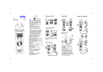
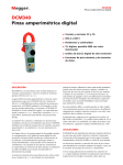
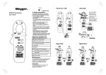
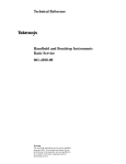
Warning Safety sheet . .. .. .. . .. .. .. . .. .. . .. .. . .. .. . .. .. . .. . .. .. .. . .. .. .. .. . .. . .. .. .. . .. . .. .. .. . . Power On / Off .. .. .. . .. Data Hold Read First DCM330 Fork multimeter User Guide Safety Information To ensure safe operation and service of the Meter, follow these instructions. Failure to observe warnings can result in severe injury or death. - Avoid working alone so assistance can be rendered. - To enhance safety, test leads should be disconnected from instrument when not in use. - Do not use test leads or the Clamp Meter if they look damaged. - Do not use the Meter if the Clamp Meter is not operating properly or if it is wet. - Use the Clamp Meter only as specified in the Instruction card or the protection provided by the Clamp Meter might be impaired. - Special precautions are necessary when operating in situations where exposed live parts at dangerous voltages may be encountered. Personal protective equipment (not supplied with this instrument) should be used. Auto Power Off VoltFinder Symbols as marked on the Tester and Instruction card Risk of electric shock See instruction card Equipment protected by double or reinforced insulation The meter will automatically shut itself off after approximately 10 minutes after power on. Battery Earth Conforms to EU directives F Application around and removal from hazardous live conductors is permitted Do not discard this product or throw away Maintenance Do not attempt to repair this Clamp Meter. It contains no user-serviceable parts. Repair or serving should only be performed by qualified personal. Cleaning Periodically wipe the case with a dry cloth and detergent do not use abrasives or solvents. AC V / DC V 1. VoltFinder can be activated on any range including OFF. 2. Test leads are not used for the VoltFinder function. 3. Press and hold the VoltFinder button. The display will go black, a tone sounds and the red LED near the fork jaw will illuminate briefly to verify that the instrument is operational. Continue to hold the VoltFinder button. 4. If a voltage of 50V to 1000V (50 to 500Hz) is detected near the jaw ,a continuous tone sounds and the red LED near the jaw illuminates. Diode / Continuity Resistance Battery Replacement CAT Application field Ⅰ The circuits not connected to mains. circuits directly connected to Ⅱ The Low-voltage installation. Ⅲ The building installation. source of the Low-voltage Ⅳ The installation. Specifications 1-1 General Specifications ACA CAT.Ⅳ.600V with respect to earth for the jaw. Tactile Barrier for hand guard. Do not hold the meter in front of the Tactile Barrier. LCD display digits : 3 1/2 digit large scale LCD readout. Display count : 2000 counts. Measuring rate : 1.5 times / sec. Overrange display : “OL” is displayed for “Ω” functions, shows the real value for “A” and “V” function. Automatic power off time : Approximately 10 minutes after power on. Low battery indicator : is displayed. Power requirement : R03 UM4 AAA 1.5V x 2 batteries Battery life : ALKALINE 250 hours. Not suitable for use with rechargeable cells. 1-2 Environmental Conditions X √ X I + (-I)=0 Indoor Use. Calibration : One year calibration cycle. Operating temperature : 0°C ~ 30°C (≦80% RH) 30°C ~ 40°C (≦75% RH) 40°C ~ 50°C (≦45% RH) Storage temperature : -20 to +60°C, 0 to 80% RH (batteries not fitted). Dimensions (W x H x D) : 54mm x 193mm x 31mm Weight : 280g including battery. Accessories : Battery (installed), Carrying case and User manual. Overvoltage category : IEC 61010-1 1000V CAT.Ⅲ. 600V CAT.Ⅳ. Operating altitude : 2000m (6562 ft) Conductor Size : 16mm diameter. Pollution degree : 2 EMC : EN 61326-1 Shock vibration : Sinusoidal vibration per MIL-T28800E (5 ~ 55 Hz, 3g maximum). Drop Protection : 1.2m drop to hardwood on concrete floor. AC Conversion Type : Average sensing rms indication. AC Current Function Range Accuracy A 0.0 ~ 200.0A (50~60Hz) ±(3.0% + 3 dgt) Overload protection : 400 Arms AC Conversion Type : Average sensing rms indication. * Adjacent conductor influence : <0.08 A/A Resistance Range Accuracy 200.0 Ω ±(1.0% + 5 dgt) *2 2.000 KΩ 20.00 KΩ ±(1.0% + 2 dgt) 200.0 KΩ 1-3 Electrical Specifications Accuracy is ±(% reading + number of digits) at 23°C ± 5°C < 80%RH. Temperature coefficient : Add 0.2 x (Specified accuracy) / °C, < 18°C, > 28°C . DC / AC Volts Range 200.0V 1000V DC Accuracy AC Accuracy ±(1.0% + 2dgt) ±(1.5% + 5dgt) 50Hz ~ 500Hz Over voltage protection : DC / AC1000V Input Impedance : 2 MΩ // less than 100pF. CMRR / NMRR : (Common Mode Rejection Ratio) (Normal Mode Rejection Ratio) VAC : CMRR > 60dB at DC, 50Hz / 60Hz VDC : CMRR > 100dB at DC, 50Hz / 60Hz NMRR > 50dB at DC, 50Hz / 60Hz 2.000MΩ 20.00 MΩ ±(1.9% + 5 dgt) *1 Overload protection : 600Vrms Open circuit Voltage : -1.3V approx. * 1 < 100 dgt rolling. * 2 < 10 dgt rolling. Limited Warranty This Meter is warranted to the original purchaser against defects in material and workmanship for 1 year from the date of purchase. During this warranty period, manufacturer will, at its option, replace or repair the defective unit, subject to verification of the defect or malfunction. This warranty does not cover , disposable batteries, or damage from abuse, neglect, accident, unauthorized repair, alteration, contamination, or abnormal conditions of operation or handling. Any implied warranties arising out of the sale of this product, including but not limited to implied warranties of merchantability and fitness for a particular purpose, are limited to the above. The manufacturer shall not be liable for loss of use of the instrument or other incidental or consequential damages, expenses, or economic loss, or for any claim or claims for such damage, expense or economic loss. Some states or countries laws vary, so the above limitations or exclusions may not apply to you. Diode Check and Continuity Resolution Accuracy 1 mV ±(1.5%+0.05 V)* Megger Limited * For 0.4V ~ 0.8V Max.Test Current : 1.5mA Max. Open Circuit Voltage : 3V Overload Protection : 600Vrms Continuity : Internal beeper activates if the resistance of the circuit under test is less than 50Ω. It will then turn off if the resistance is increased beyond 250Ω. Response time is approximately 0.25~1 sec. Archcliffe Road, Dover, CT 17 9EN United Kingdom Tel +44 (0) 1304 502100 Valley Forge Corporate Centre 2621 Van Buren Avenue, Norristown PA 19403, USA Tel +1-979-690-7925 Email [email protected] Web www.megger.com