1
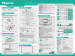
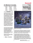
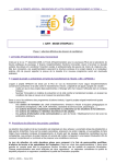
DataBand E1T1 Quickstart Guide V3.2
© 2012 Patapsco Designs Ltd
Patapsco has recently been acquired by Communications Systems, Inc. (CSI) and is now a part of Transition Networks, Inc., a
subsidiary of CSI. The high-quality, reliable Transition Networks’ brand of products is now combined with the world class
portfolio of telecommunications and data communications products from Patapsco Communications.
You can be assured that the same quality and support from both organizations will continue. Please contact either Transition
Networks or Patapsco Communications for sales, support and product information.
Patapsco Communications
The Passfield Oak, Passfield, Near Liphook,
Hampshire
GU30 7RL UK
Transition Networks
10900 Red Circle Drive
Minnetonka
MN 55343 USA
Tel: +44 (0) 1428 752900
Fax: +44 (0) 1428 752901
Email:
[email protected]
Web Site: www.patapsco.co.uk
Tel: 952- 941-7600 or 1-800-526-9267
Fax: 952-941-2322
Email:
[email protected]
Web Site: www.transition.com
All rights reserved. No parts of this work may be reproduced in any form or by any means - graphic, electronic, or mechanical, including photocopying, recording, taping, or information storage and retrieval
systems - without the written permission of the publisher.
Products that are referred to in this document may be either trademarks and/or registered trademarks of the respective owners. The publisher and the author make no claim to these trademarks.
While every precaution has been taken in the preparation of this document, the publisher and the author assume no responsibility for errors or omissions, or for damages resulting from the use of information
contained in this document or from the use of programs and source code that may accompany it. In no event shall the publisher and the author be liable for any loss of profit or any other commercial damage
caused or alleged to have been caused directly or indirectly by this document.
Printed: March 2012 in UK
2
DataBand E 1T1 Quickstart G uide
Table of Contents
1. Introduction
3
1.1 Transition
Networks - Patapsco
...................................................................................................................................
3
1.2 Safety warnings
................................................................................................................................... 3
2. Getting Started
3
2.1 Rack Mounting
Instructions
...................................................................................................................................
4
2.2 Accessories
................................................................................................................................... 4
2.3 Optional
Accessories
...................................................................................................................................
4
2.4 Making ...................................................................................................................................
Connections
5
2.5 Installing
DbManager
...................................................................................................................................
5
3. Configuring DataBand E1T1
5
3.1 Connecting
to DataBand E1T1
...................................................................................................................................
6
3.2 Notes on
configuring DataBand E1T1
...................................................................................................................................
7
3.3 Identifier
and Ethernet Settings
...................................................................................................................................
8
3.4 ISDN Port
Configuration
...................................................................................................................................
8
3.5 Clock Sources
................................................................................................................................... 8
3.6 Finishing
Configuration
...................................................................................................................................
8
3.7 More Resources
................................................................................................................................... 8
© 2012 Patapsco Designs Ltd
Introduction
3
1. Introduction
This document is a basic guide for configuring a new Patapsco DataBand E1T1. A full User Manual for configuring all settings on the unit is supplied on
the DbManager Installation Disk. Patapsco offers an optional Pre-Configuration Service and optional Telephone Support Agreements at minimal cost.
Information on these options can be found in the Support document on the DbManager installation disk.
1.1. Transition Networks - Patapsco
Patapsco DataBand products allow cross-connectivity of E1 and T1 ports and timeslots between any source and destination connected to the unit.
Conversion of E1 to T1 and vice versa is catered for, as well as conversion between A-law and µ-law voice calls, while the DataBand E1T1 range allows
simple conversion between the E1 and T1 protocols. The EV device allows conversion between V.35 and E1/T1 protocols.
1.2. Safety warnings
Caution: Danger of electric shock. The device may be connected to mains voltages. Switch to power-off state before
working on the device.
Caution: Danger of electrostatic discharge. Electronic components are sensitive to electrostatic discharges that might
damage the device. Protect the device from electrostatic discharges by wearing an electrostatic wristband.
Caution: Interruption of data transmission. Data transmission will be interrupted during any work on the transmission
line and/or deactivation of the power supply. Make sure that that any work will only be carried out on inactive lines
(without data transmission) or during quiet times to reduce interference to live systems.
Caution: Danger of damage to devices or service interruption. Access by unauthorized third persons may cause damage
to devices and/or interrupt services. Make sure that subracks are only installed in lockable locations.
Caution: Danger of overvoltage. During faults, dangerous unprotected voltages may be present. Ensure sufficient
grounding of the housings, i.e. by connecting the grounding contact.
Safety requirements are not fulfilled unless this equipment is connected to a wall socket outlet with a protective earth (PE)
contact.
The power cord used to connect this equipment must be HAR marked and fitted with an IEC320 connector and an ASTA
approved moulded plug.
There are no user serviceable parts in this equipment. All servicing and repair tasks must be undertaken by qualified service
personnel.
Isolation from mains power is achieved by the removal of the main power cord.
2. Getting Started
This section will describe how to make the physical connections between DataBand E1T1 and the other system devices, and install the Patapsco
management application, DbManager.
© 2012 Patapsco Designs Ltd
4
DataBand E 1T1 Quickstart G uide
2.1. Rack Mounting Instructions
The Rack Mounting Kit is comprised of the following:
Photo
Description
Quantity
L- Bracket
2
Long P atapsco case screw
4
Cage N ut
4
washer
4
Rack Mount Screw
4
All Patapsco units can be mounted in a standard 19" rack housing. To allow units to fit into a 19" rack, a Rack Mounting Kit must be purchased for the unit
(s). There are various rack mounting options depending on the size of the unit ordered. The following guide will explain how to use the Rack Mounting Kit
with Patapsco units.
1. Remove the four short screws near the front or rear panel on the left and right hand sides of the Patapsco unit. The unit can be mounted with the front
panel facing forward or with the ports facing forward as required.
2. Fit one of the L - Bracket s to the side of the unit. The four small fixing holes allow the unit to protrude forward or sit further back depending on the desired
position of the unit. The bracket may also face forwards or backwards depending on the desired position of the unit.
3. Fix the L - Bracket in place using the L on g P at apsco case screws.
4. Fix the second L - Bracket to the other side of the case in the same way.
5. Put the R ack Mou n t screws through the R ack Mou n t wash ers.
6. Offer the unit up to the rack and fix it in place using the R ack Mou n t Screws and R ack Mou n t cage n u t s.
2.2. Accessories
The following accessories are supplied with all Patapsco units:
I t em
DbManager CD
D escri pt i on
Installable DbManager application, technical documents and manuals
Cable Spec
Management cable. Connects to
RJ12
DataBand E1T1'sTerminal port
Pin
Function
1
Rx
2
Tx
3
Gnd
Connects DataBand E1T1 to the mains supply
Controller Cable
IEC Mains Cable
DB9S
Pin
3
2
5
2.3. Optional Accessories
The following items can be ordered from Patapsco, or will be supplied with some units depending on the nature of the device.
I SD N C abl es R ack Mou n t i n g Ki t -
Cables to connect the Patapsco device to a CPE or network. Please see the full manual for cable specs on all
Patapsco cables
All Patapsco units can be monuted in a 19" rack using this kit
© 2012 Patapsco Designs Ltd
G etting Started
5
2.4. Making Connections
First, connect the ISDN cables to DataBand E1T1 followed by the Terminal Port management cable (if required), LAN Port cable and lastly the Mains cable.
If the unit has a DC power supply connection, use the screw terminals to connect the DC power source.
W arning: The -48VDC power terminals are marked 0V, - 48V, and G N D. Patapsco -48VDC products are designed for use
with negative voltage DC supplies, and therefore expect the positive voltage to be connected to the 0V terminal, and the
negative connected to - 48V. Please be sure about the polarity of this connection before connecting power to the terminals.
Units which have a positive +24VDC power source will be marked +24VDC, 0V and G N D respectively. Please ensure that
the positive connection is made on the +24VDC terminal.
2.5. Installing DbManager
DbManager is required in order to monitor and manage Patapsco devices. Management can be made using the Terminal (serial) port, or using TCP/IP over
a LAN or WAN. DbManager is installed using the CD provided with Patapsco equipment.
1. Insert the DbManager Installation Disk into the drive of the PC which will be used for management of DataBand E1T1.
2. InstallShield Wizard will start up. Follow the steps to install DbManager.
3. Serial Number – Enter the Serial Number on the case of the DbMgr Disk.
Info: DbManager is supplied as a 'Lite' version by default. This allows configuration and monitoring of devices, but only allows
configuration of a single device node and a single user account. To use DbManager in 'Lite' mode, do not enter a serial
number during installation. Please see the full DbManager User Manual for more information on configuring and using
DbManager.
W arning: If an older version of DbManager is already installed on the management PC, it is necessary to update to the
version supplied on the new DbManager CD. This can be done by consulting the ‘Upgrade’ folder on the DbManager CD. The
‘readme.txt’ file explains how to upgrade to the new DbManager without reinstalling the program.
3. Configuring DataBand E1T1
Follow these steps to connect to DataBand E1T1 with DbManager and configure the unit for use.
Configuration of DataBand E1T1 is carried out by setting up DbManager to make a management connection, and then setting up the elements of
DataBand E1T1 in this order:
I den t i f i er an d E t h ern et set t i n gs I SD N P ort Set t i n gs C l ock Sou rces -
© 2012 Patapsco Designs Ltd
The IP address settings and unique Identifier of the unit
Settings for the ISDN ports
configure which interface DataBand E1T1 is to take synchronisation clock from
6
DataBand E 1T1 Quickstart G uide
3.1. Connecting to DataBand E1T1
1. Start up the DbManager Application
2. Login as Su per U ser (no password required)
3. Four windows will be displayed:
Map
A n et work m ap sh owi n g Nodes an d L i n ks bet ween P at apsco dev i ces
Terminal
A v i ew of t h e com m u n i cat i on s bet ween D bMgr an d D at aBan d E 1T1
Event History
A l l ev en t s wh i ch occu r wh i l e con n ect ed t o D at aBan d E 1T1
Outstanding Events
C u rren t ev en t s
4. Select Vi ew
P ropert i es
Term i n al from the DbMgr toolbar.
5. Choose the COM port which is in use. Leave the Seri al P ort R at e at the default setting of 19200bps. Click O K.
6. Select the D ev i ces i n W orl d window and double click the D ev i ce node
7. The C on n ect ed t o D ev i ce window should appear, showing the front and rear panels of DataBand E1T1. If it does not, check the COM port settings
and re-try
W arning: If management via the Terminal port is not possible, it could be that the management PC has another application
running which uses the COM ports of the PC. Even when some programs which use the COM ports are closed down, other
programs cannot access the COM ports. Rebooting the PC is required in order to release the COM ports so that DbManager
can use them.
If the PC and DataBand E1T1 are connected to the same LAN, management is possible using TCP/IP. All Patapsco products use the default IP settings:
I P A ddress
Su bn et Mask
Gat eway
192.168.0.1
255.255.0.0
0.0.0.0
To configure DbManager to access DataBand E1T1 using TCP/IP, please follow these steps:
1. Select Vi ew
P ropert i es
Term i n al
D ev i ce I P A ddresses from the DbMgr toolbar
2. 192.168.0.1 should already be configured. If using another IP address, add it to the list using the A dd button
3. Click O K
OK
4. Select the D ev i ces i n W orl d window and double click the Device node
5. The Connected to Device window should appear, showing the front and rear panels of DataBand E1T1
The Device node can be made to connect to other IP addresses configured in the D ev i ce I P A ddresses list by right-clicking the node, selecting
P ropert i es and choosing an IP address from the I P L i st .
Info: TCP/IP management requires TCP port 3001 (dec) to be open between the management PC and DataBand E1T1. Any
switches, hubs or routers must be configured to allow communication on this port in order to manage DataBand E1T1 via TCP/
IP.
© 2012 Patapsco Designs Ltd
Configuring DataBand E 1T1
7
A successful management connection will open up the C on n ect ed t o D ev i ce window:
3.2. Notes on configuring DataBand E1T1
Uploading
Changes to config can be made on each window and saved using the OK key when exiting each window. When happy with the
configuration, it must be uploaded to DataBand E1T1 for the new settings to come into effect.
To upload, go to F ile
Upload or press the Upload button on the config window and wait until the progress bar completes.
Sav ing F iles
Configuration files can be saved in order to backup settings or copy settings across to another unit. Once configuration has been
uploaded, go to F ile
Sav e F ile and choose a location to save the file to. The file extension of any saved config files is .dbc
Loading F iles
Once connected to a unit, an existing configuration file can be loaded to the device. Go to F ile
Open F ile and navigate to the
saved file. Click Open. Now the file must be uploaded to DataBand E1T1. Go to F ile
Upload or press the Upload button on
the config window and wait until the progress bar completes.
W arning: When loading existing configuration files to a unit, please ensure that the correct configuration files are used for the
unit type in use. DataBand E1T1 configuration files are not compatible with other Patapsco platforms.
© 2012 Patapsco Designs Ltd
8
DataBand E 1T1 Quickstart G uide
3.3. Identifier and Ethernet Settings
This menu controls the I P A ddress, Su bn et Mask, D ef au l t Gat eway and I den t i f i er. Enter a unique Identifier and IP settings for the unit. These
features are all fully explained in the DataBand E1T1 User Manual on the DbManager Installation Disk.
3.4. ISDN Port Configuration
Set the TDM ports to E1 or T1 mode. T1 ports have options relating to the T1 Line Code and Framing type. Please consult the documentation of the
connected CPE if unsure of the correct settings to use.
There are two LEDs for each TDM port, and the LED states are as follows:
Top LED on Bottom LED on -
Layer 1 and 2 established
Channels active on interface
3.5. Clock Sources
DataBand E1T1 must be configured to either receive clock from an ISDN interface, a connection to another DataBand E1T1 or generate clock internally.
Different priorities can be set for each port, so if one port is unavailable, DataBand E1T1 will clock from the next available port in the Clock Source
hierarchy.
Enter a digit to mark the priority of each ISDN port and the internal clock. 0 will denote the highest priority Clock Source and 19 will denote the lowest.
Ports which are not to be used for clocking can have their values left at 19.
W arning: Clock Sources must be configured correctly to ensure error-free operation when DataBand E1T1 is connected to any
other clock-locked system or network. Please consult the full DataBand E1T1 manual if unsure how to configure Clock Sources.
3.6. Finishing Configuration
N ote: Please remember to Upload when configuration of DataBand E1T1 is complete. To upload, go to F ile
press the Upload button on the config window and wait until the progress bar completes.
Upload or
3.7. More Resources
All Patapsco products and the DbManager application have their own User Manuals which can be found in the 'Documents & Manuals' folder on the
DbManager installation disk. Please consult these manuals for more detailed information on any aspect of using Patapsco products. All documentation can
also be obtained by registering at the Patapsco website:
http://www.patapsco.co.uk/Top_Level/LogIn_Register.asp
For help with a specific problem, please click on the O n - L i n e H el p icon on the website, or email a request to [email protected]
© 2012 Patapsco Designs Ltd