1
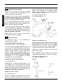
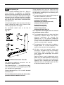
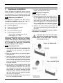
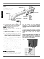
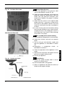
Fig. 13.
The flue length is measured from the
centreline of the appliance flue outlet to the
inside of the external wall-sealing ring. In
most cases it will be possible to achieve the
required flue length without cutting the ducts,
however where necessary the plain ends of
the extension ducts may be cut. Never cut the
swaged end, and always ensure that the cut
is square and free of burrs or debris.
NOTE IT IS ESSENTIAL THAT THE TERMINAL
IS FITTED THE CORRECT WAY UP See flue
kit Instructions (i.e. rain shield at the top).
Fig. 14.
Measuring the exact flue length
TOTAL FLUE LENGTH
FROM FLUE OUTLET
CENTRE TO OUTSIDE
WALL FACE:
= LENGTH L
•
L
WALL
4.7
Air/Flue Duct Installation
For correct flue installation please refer to the
installation instructions that are provided with
the individual flue kit as described in sections
2.5 - 2.6.
a) Measure the required flue length as shown in
Figure 14. Refer to section 2.5 to determine
whether any extension kits are required.
Installations using only the standard ducts or
standard ducts with straight extensions are
described in this section. Installation
instructions for all other flue systems are
included in the various flue kits.
b) Ensure that all (inner and outer tube) sealing
rings are provided and assemble the air/flue
ducts as shown in the flue instructions.
c) Construct the correct flue length by building
the flue out from the appliance. Ensure that
the flue and air seals are correctly fitted
before assembly and that each section is
fully engaged.
OUTLET
INTERNAL
Dia. 60mm
•
••
•
4.7.1 Installing the air/flue duct from inside
the room
a) Push the terminal through the wall liner taking
care to ensure that the terminal is the correct
way round and the external wall-sealing ring
does not become dislodged.
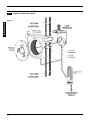
b) Assemble the flue system extension ducts as
necessary, referring to Figure 15.
c) Pull the flue system towards the appliance to
seat the external sealing ring against the
outside wall, ensuring that the duct joints are
not disturbed.
d) Use the internal sealing ring to make good the
internal hole, and check that the terminal is
correctly located on the outside wall (Where
possible this should be visually checked from
outside the building.) Figure 15 shows a view
of the flue system, correctly installed.
19
INSTALLATION
Condensate Connections