1
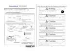
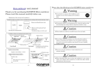
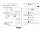
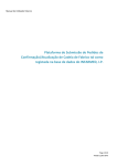
user’s manual 書 Thank you for purchasing OLYMPUS Micro cantilever. Please read this manual carefully before use. Please obey the following to the OLYMPUS micro cantilevers Warning Use protective eye glasses when handling to avoid <Explanation of the each part of the products> Cantilever chips in a plastic case are included in the envelope with manual and spec, sheet. damage to the eyes from breakage of the cantilever chips. Manual and Specification sheet Label Inside Caution Plastic pack (translucent blue) Plastic case (Cantilever chips are in the case) Envelope for transportation Please handle our cantilevers carefully because they are fragile. Cantilever chips are contained in the plastic case (Tac carrier) Adhesive sheet Cantilever chips Case (Tac carrier) Caution Upside Down side Cantilevers are tip-side-up as viewed in the case. Case Label Tape Case (closed) Case (open) Do not drop or shake the cantilever case. Even when the cantilever chips are contained in the cantilever case, the cantilevers may break if the case is handled roughly or jarred. Caution Magnified illust. Case label OMCL-AC240TS-C2 Products name Lot Number Cantilever Cantilever chip (substrate) It is recommended that precautions be taken to prevent damage to the cantilever tips from electrostatic discharge. 70 Caution 2 Inspection stamp One cantilever elongates from the side of round shoulders of the chip. When discarding, please obey the laws and regulations in your country and/or your company. These cantilever are made from silicon and aluminum. - 1e - - 2e - 1 Special feature of OLYMPUS Micro cantilever (OMCL-AC240TS-C2) 1. AC mode cantilever – This type of micro cantilever is for AC (dynamic) mode AFM operation. High mechanical Q factor of the cantilevers allows you high sensitivity measurement to probe your sample surface gently. 1) Please prepare the followings before using OLYMPUS cantilevers. 2) To gain a better understanding of how cantilevers and chips are connected, cantilevers should be inspected under the microscope. 1) Work environment :Clean bench (Use of an electrical charge neutralizer of ionizer is recommended.) 2) For hazard avoidance :Protective eye glasses 3) For cantilever treatment:Tweezers, Thin bamboo stick (Use of anti-electrostatic discharge mat and a wrist band is recommended.) 4) For inspection :Stereo microscope 2. Pre-separated chip – Each cantilever chips is isolated in the case. The chips can be attached to the AFM instrument as soon as the case is open. 3. Tip View – The tip is located on the very end of the cantilever. This feature allows you to set the tip over a point of interest on the sample, easily and precisely, if you use an AFM combined with an optical microscope. 4. Point terminated tip – The tip radius is typically 10 nm or less. A sharpened tetrahedral tip of single crystal silicon is employed for high-resolution measurements. The tetrahedral shape is ideal for achieving a point terminated tip. In addition to the geometrical dimensions of the tip, the tip is further sharpened with our exclusive sharpening process. Preparation 3) Wind both-side adhesive tape around the top of the thin stick to prepare an adhesive stick for picking up the chips from Tac carrier case. 4) Cut the top of the wound adhesive tape with scissors to make the top of the adhesive flat. 5. Symmetric tip – The tetrahedral tip is thin with the macroscopic tip angle of 35 degrees viewing from both its front and side. Tip shows good symmetry in viewing along the cantilever axis (see Chapter 5). Symmetric shape tip results AFM images less distortion which reduce misinterpret of the data. 6. Reflex coating cantilever – Aluminum is coated onto the back side of the cantilevers for optical deflection sensing. Good S/N signal can be expected in the optical sensor circuit. 7. Compatible chip – The thickness of the chip (substrate) is 0.3 mm. This type of the chip can be attached to most of AFM instruments. 2 See the specification sheet of OLYMPUS Micro cantilevers at the last page of this manual. Table of contents page 4e 1 Preparation 2 Open the case 4e 3 Picking up the cantilever chip 5e 4 Attaching the cantilever chips to your instrument 6e 5 Tip shape of Tetrahedral tip 7e 6 Information 8e 7 Specification 1s - 3e - Open the case Caution Please handle our cantilevers carefully because they are fragile. Caution It is recommended that precautions be taken to prevent damage to the cantilever tips from electrostatic discharge. 1) It is recommended that the cantilever case be opened in a clean environment like a clean bench in order to avoid the cantilever being contaminated. Handling under an ionizer is recommended. 2) Avoid wearing clothes like woolen sweaters, fleece etc that give off the static electricity when handling the cantilever cases and chips. Use of an anti-electrostatic mat and wrist band is preferable. - 4e - 3) In opening the case, put the plastic case label-side down on a desk. The cantilevers are tip-side-up as viewed in the case. 4) Open the case. 4 Attaching the cantilever chips to your instrument 1) Please read the instruction manual of your scanning probe microscope before this operation. To attach the cantilever chip to the holder in your scanning probe microscope, Picking up the cantilever chip from the case 3 Caution Avoid any contact with the cantilevers when you pull up the cantilever tip from the case. Caution 2) Place the chip on the adhesive stick gently against the prescribed part in your chip holder. (see left below) 3) Press the center of the chip with sharp pointed tweezers and pull apart the stick from the chip. (see right below) 4) Lock the chip into the chip holder in accordance with the manner described in the manual of your SPM. Most of the chip holders in AFMs use a leaf spring or a wire for pressing the chip to the holder. It is recommended that the chip be pressed with those at the center of the chip to achieve a good mechanical coupling between the chip and the holder. Cantilever chips should always be placed tip-side-up. 1) Press down gently on the part between the center and one third of the chip along the center line with the adhesive stick (see left below) 2) Do not press the chip too much, or the chip might be buried in the Gel sheet and the cantilever must break. 3) Pull up the tick carefully, then the adhered chip is picked up together (see below). Note : Note) To avoid contact with the cantilever, the tweezers should not access to the chip from cantilever side. Put the tweezers on the chip like following illustration. Some of the both-side adhesive tapes have not enough adhesive to pick up the chip from the Gel sheet. Then use the tweezers for this procedure. - 5e - - 6e - 5 Tip shape of Tetrahedral tip As can be seen in the left illustration, a tetrahedral tip is located at the exact end of the cantilever. The finite tip shape will determine the Scan line profile as in the illustrations below. The tip profile is symmetric with a half tip angle of 18 degrees macroscopically (see left below). The side tip profile is asymmetric with a tip angle of 35 degrees. Then the cantilever chip is attached to a chip holder in your AFM with an angle, about 10 degrees, the asymmetry is improved (see right below). A A’ B When you set your samples to your instrument, please consider the unique shape of the tetrahedral tip, that is ‘good symmetry’, when viewing from its front side and choose the direction of the sample. When measuring long grooves, you can get an idea of what angle of the cut will be quickly by aligning the cantilever along the grooves and scanning across at right angles against grooves (see below). B’ 6 Information Please contact following if you have any question on this user’s manual. Tip shape and scan line profile The apex of the tetrahedral tip becomes sharper due to an oxide sharpening process. The tip angle around a few hundreds nano meter down from the apex, is about 15 to 25 degrees (see below). OLYMPUS CORPORATION Microtechnology R&D Division 2-3 Kuboyama-cho Hachioji-shi Tokyo 192-8512 Japan email : [email protected] Please access to the web page of OLYMPUS micro cantilevers. http://www.olympus.co.jp/probe Ver. 2.0 June 22, 2009 OLYMPUS CORPORATION - 7e - - 8e -