1
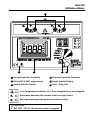
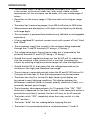
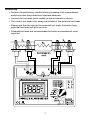
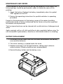
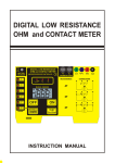
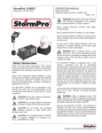
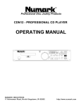
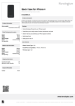
99 Washington Street
Melrose, MA 02176
Phone 781-665-1400
Toll Free 1-800-517-8431
Visit us at www.TestEquipmentDepot.com
MO-100
Milliohm Meter
Users Manual
•
•
•
•
Mode d’emploi
Bedienungshandbuch
Manual d’Uso
Manual de uso
MO-100
Milliohm Meter
English
Users Manual
July 2009, Rev.1
©2009 Amprobe Test Tools.
All rights reserved. Printed in Taiwan
Limited Warranty and Limitation of Liability
Your Amprobe product will be free from defects in material and workmanship for 1 year from the
date of purchase. This warranty does not cover fuses, disposable batteries or damage from accident,
neglect, misuse, alteration, contamination, or abnormal conditions of operation or handling. Resellers
are not authorized to extend any other warranty on Amprobe’s behalf. To obtain service during the
warranty period, return the product with proof of purchase to an authorized Amprobe Test Tools
Service Center or to an Amprobe dealer or distributor. See Repair Section for details. THIS WARRANTY
IS YOUR ONLY REMEDY. ALL OTHER WARRANTIES - WHETHER EXPRESS, IMPLIED OR STAUTORY INCLUDING IMPLIED WARRANTIES OF FITNESS FOR A PARTICULAR PURPOSE OR MERCHANTABILITY,
ARE HEREBY DISCLAIMED. MANUFACTURER SHALL NOT BE LIABLE FOR ANY SPECIAL, INDIRECT,
INCIDENTAL OR CONSEQUENTIAL DAMAGES OR LOSSES, ARISING FROM ANY CAUSE OR THEORY.
Since some states or countries do not allow the exclusion or limitation of an implied warranty or of
incidental or consequential damages, this limitation of liability may not apply to you.
Repair
All test tools returned for warranty or non-warranty repair or for calibration should be accompanied
by the following: your name, company’s name, address, telephone number, and proof of purchase.
Additionally, please include a brief description of the problem or the service requested and include
the test leads with the meter. Non-warranty repair or replacement charges should be remitted in the
form of a check, a money order, credit card with expiration date, or a purchase order made payable to
Amprobe® Test Tools.
In-Warranty Repairs and Replacement – All Countries
Please read the warranty statement and check your battery before requesting repair. During the
warranty period any defective test tool can be returned to your Amprobe® Test Tools distributor
for an exchange for the same or like product. Additionally, in the United States and Canada In-.
Warranty repair and replacement units can also be sent to a Amprobe® Test Tools Service Center
(see address below).
Non-Warranty Repairs and Replacement – US and Canada
Non-warranty repairs in the United States and Canada should be sent to a Amprobe® Test Tools
Service Center. Call Amprobe® Test Tools or inquire at your point of purchase for current repair
and replacement rates.
Test Equipment Depot - 800.517.8431 99 Washington Street Melrose, MA 02176
TestEquipmentDepot.com
MO-100
Milliohm Meter
1
2
3
5
4
6
1 Current Injection Terminals
2 Potential Injection Terminals
3 Meet LVD & EMC requirement
4 Liquid Crystal Display
5 Rotary Selector Switch
6 Start / Stop Test
Over Temperature indicator. Lit = Over-temperature or test stopped.
Resistance between the current leads too high (fuse!).
Resistance between the potential leads too high.
�CAUTION!
If “NO TEST” LED lit, the current source is stopped.
MO-100
Milliohm Meter
CONTENTS
SYMBOLS................................................................................................................2
CAUTIONS AND PRECAUTIONS ............................................................................2
UNPACKING AND INSPECTION .............................................................................3
INTRODUCTION......................................................................................................4
OPERATION.............................................................................................................6
Preparation For Use ..........................................................................................6
Check the Battery .............................................................................................6
Check the Current Regulation . ........................................................................6
Check the Voltage Measurement ....................................................................6
Measuring .........................................................................................................7
Test Leads ..........................................................................................................8
Supplied Potential Test Leads . .........................................................................8
Supplied Current Test Leads .............................................................................8
Thermal Effects .................................................................................................9
SPECIFICATION ......................................................................................................10
Electrical ............................................................................................................10
Mechanical ........................................................................................................10
Rated environmental conditions . ....................................................................11
MAINTENANCE AND REPAIR.................................................................................12
Battery Replacement ........................................................................................12
Fuses Replacement . ..........................................................................................13
1
SYMBOLS
�
Caution ! Refer to the explanation in this Manual
�
Caution, Risk of Electric Shock
�
Please remove all the test leads before performing maintenance,
cleaning, battery replacement, fuse replacement, etc
�
Conforms to relevant Australian standards
�
Complies with European Directives
=
Do not dispose of this clamp meter as unsorted municipal waste.
Contact a qualified recycler for disposal.
�WARNING!
Do not operate this instrument in the presence of gasoline, natural gas,
propane, or in other combustible atmospheres.
Cautions and Precautions
Refer to this manual before using the meter
• This instrument should only be used by a competent, suitably trained
person which fully understand the test & measurement procedure.
• Read the User’s manual carefully and completely before using the
instrument. Fully understand the instructions before using this product.
Follow the instructions for every test. Take all the necessary precautions.
Do not exceed the limits of this instrument.
• The tested circuit must be de-energised and isolated before connections
are made to it.
• Do not use test leads, probes or crocodiles/aligators clips that are dirty,
damaged or have broken or cracked insulation. Such accessories should
be removed and repaired Immediately.
• Always disconnect the test leads before replacing any fuse or battery.
• Always replace the fuse with same type and rating; ensure that they are
correctly fitted on fuse terminals.
• Double check the switch settings and leads connections before
measuring. Make a sketch to ensure proper operation and principle of
measurement is correct and well understood.
• Do not touch any exposed wiring, connections or other “live” parts of
an electrical circuit. If in doubt, check the circuit first for voltage before
touching it.
Test Equipment Depot - 800.517.8431 99 Washington Street Melrose, MA 02176
TestEquipmentDepot.com
Precautions
• Always ensure that the circuit to be measured is switched “OFF”,
isolated and completely de-energized before connecting the test leads.
• If it is probable that the instrument’s protection has been impaired due
to electrical, mechanical or environmental damage, it must not be used.
It should be returned to your nearest distributor or agent for checking
and repair.
• To prevent damage to the liquid crystal display, the minimum storage
temperature of -20°C must be observed. It should also be noted that
below 0°C the operation of the LCD will be sluggish
�Warning, risk of electric shock.
Unpacking and Inspection
Your shipping carton should include:
1
MO-100 Milliohm Meter
1
Shoulder Belt
1
Test Lead (Green Color)
1
Test Lead (Red Color)
1
Test Lead (Blue Color)
1
Test Lead (Black Color)
8
Alkaline Battery (SIZE AA, 1.5V)
1
Spare Fuse (0.5A/ 250V)
1
User’s Manual
If any of the items are damaged or missing, return the complete package to
the place of purchase for an exchange.
3
INTRODUCTION
• The Milliohm Meter is a battery operated instrument wich supply
a low current to the circuit under test, with which, stable, accurate
measurement of low resistance can be made, still, over a wide range of
values.
• Resolution on the lowest range is 100μ ohm and on the highest range,
1 ohm.
• The meter has 5 measuring ranges, from 200.0 milli-ohm to 2000 ohms
• Measurements are displayed on a 3½ digit custom liquid crystal display
with large digits.
• This instrument is powered from batteries only (alkaline or rechargeable
equivalent).
• It has a regulated DC constant current source with current of 1mA 10mA
and 100mA.
• The instrument supply that current to the resistance being measured
through the C1 and C2 terminals (C1 being +, C2 being -).
• The voltage drop across the resistance under test is measured by the
potential terminals P1 and P2 (P1 being +, P2 being -).
• Should the current regulation drops out, the Rc LED will lit, indicating
that the resistance in the current circuit is too high. (Lowering the
current by selecting a higher resistance range can solve the regulation.)
• Should the Rp LED lit, that mean that the voltage measured on the
resistance is too high, and therefore over-range.
• The resistance is measured precisely when the RP and RC LEDs do not lit.
If anyone of these leds lit, then the measurement can be inaccurate.
• The meter has a built-in custom 3½ digit liquid crystal display can
be viewed in most lightning conditions. This display indicates the
differences conditions (Hold, m, buzzer, polarity condition of load, + or -,
automatic decimal point change).
• The instrument takes measurements for 10 seconds if the “ON” “TEST
Re button is depressed for less than 2 seconds. If the same push button is
pressed for more than 3 seconds, the test will carry on for 60 seconds.
• The tester switch “OFF” completely when the rotary switch is in the
“OFF” position.
• The tester “Hold” the last reading before stopping the test.
• The tester is fuse protected and has a crowbar between C1 and C2.
4
• This crowbar is activated by voltage. If the voltage is too high, that
crowbar will blow the fuse automatically to interrupt the circuit.
• The voltage between P1 and P2 is also protected for over voltage but
does not have a fuse.
• The tester has a temperature shut down. The temperature sensing is
done on the current regulation transistor.
• Should this over-temperature LED lit, allow the instrument to cool down
for a while before proceeding further.
• The milliohm meter, with its measuring range of 100u ohms to 2000
ohms, is suitable for a wide range of applications such as:
1. Measuring the winding resistance of electric motors, generators and
transformers.
2. Bond testing in mines, aircraft, railways, ships, domestic andindustrial
wiring installations.
3. Measuring the ring main continuity testing in industrial and domestic
wiring installations
4. Measuring resistance in electronic equipment such as shunts, pcb
tracks, switch and relay resistance.
5. Checking compression joints on overheads lines.
6. Testing and maintenance of switchboard /sub-station equipment on
such items as fuses, joints, contacts and bonds.
Test Equipment Depot - 800.517.8431 99 Washington Street Melrose, MA 02176
TestEquipmentDepot.com
Operation
Preparation For Use
When unpacked, the tester should be inspected for any visible signs of
damage, and the preliminary checks described in the user’s manual should
be performed to ensure that it is operating correctly. If there is any sign of
damage, or if the instrument does not operate correctly, return it to your
nearest supplier.
Check the Battery
If the battery symbol is shown on the LCD, then replace the batteries with new
alkalines batteries before proceeding.
Check the Current Regulation
• Connect the current leads to C1 and C2.
• Select a range, and short the current test leads. The RC led should go off,
indicating that the current regulation is ok.
Check the Voltage Measurement
• Connect the potential leads to P1 and P2.
• Short the P1 and P2. The display should indicate 0000.
• Remove the short from P1 and P2and C1 and C2. Touching the potential
test leads P1 to C1 and P2 to C2, the RP led should lit, indicating an overvoltage or over-range.
This proving test can be repeated on all the ranges if need be.
You can also check the polarity indication of the milli-voltmeter by touching
the potential test leads P1 to C2 and P2 to C1, the RP LED should lit, indicating
an over-voltage or over-range. The - indicator should be indicating - on the
LCD, showing the polarity change.
Total check can be done by shorting all the test leads together C1, C2, P1, P2.
The display should indicate close to 0000 (depending of the crocodiles clips
used and how they are shorted). Both RC and RP LED should be OFF, indicating
that everything work ok.
6
Measuring
• Perform the preliminary checks before proceeding with measurement
and ensure that the precautions listed are observed.
• Connect the test leads (color coded) to the instrument as shown.
• The current test leads must always be outside of the potential test leads.
• Please note that the shorter the potential test leads, the better long
potential test leads will pick up noise.
• Screened test leads are recommended for better environmental noise
rejection.
7
Test Leads
The test leads supplied with the instrument are suitable for connecting to
conductors up to 17mm in diameter or bus bars 17mm tick. There will be,
instances where the item being measured require larger jaws, and the user is
advised to make up his own leads. There will be occasions when longer leads
are required due to the geometry of the item being tested. Some guidance
notes should as sit in the assembly of such leads:
• Length of the potential leads should be as short as possible.
• Insulated 16/0.2mm, tinned copper wire is recommended.
• The two potential leads should have the same length to minimize
inaccuracies due to unbalance.
Supplied Potential Test Leads
• P1+ test lead is of Red color, shrouded, 4mm safety plug which at one
end have a crocodile (alligator) clip for connection to the resistance to
be measured. The other end plugs into the meter (4mm shrouded) color
coded sockets.
• P2 - test lead is of Blue color, shrouded, 4mm safety plug which at one
end have a crocodile (alligator) clip for connection to theresistance to
be measured. The other end plugs into the meter (4mm shrouded) color
coded sockets
Supplied Current Test Leads
• C1+ test lead is of Green color, shrouded, 4mm safety plug which at one
end have a crocodile (alligator) clip for connection to the resistance to
be measured. The other end plugs into the meter (4mm shrouded) color
coded sockets.
• C2 - test lead is of Black color, shrouded, 4mm safety plug which at one
end have a crocodile (alligator) clip for connection to the resistance to
be measured. The other end plugs into the meter (4mm shrouded) color
coded sockets.
Test Equipment Depot - 800.517.8431 99 Washington Street Melrose, MA 02176
TestEquipmentDepot.com
Thermal Effects
• Temperature can have a significant effect on the performance of a
milliohm meter due to the temperature coefficient of the resistance
under test and thermal EMF’s across the dissimilar conductors.
• Most conductors have a large temperature coefficient of resistance. For
example: 0.4%/°C for copper. A copper conductor that has a resistance
of 10.00m ohm at 20°C will increase to 10.40m ohm at 30°C. This change
should be taken into account when making measurements.
• A current going through a resistance will also elevate its temperature. So
duration of the test can change the resistance.
• When measuring the resistance of item, such as current shunts, which
have joints of dissimilar conductors, thermal EMF can affect the accuracy
of the measurement. This condition can be detected if the reading alters
when the leads are reversed. To compensate for this effect, the average
of the two readings should be taken as the true measurement.
9
SPECIFICATION
Electrical
Measuring Ranges :
0 - 200.0m ohms in steps of 100μ ohm
0 - 2000m ohms in steps of 1m ohm
0 - 20.00 ohms in steps of 10m ohm
0 - 200.0 ohms in steps of 100m ohm
0 - 2000 ohms in steps of 1 ohm
Accuracy :
±0.5% of reading ±2 digits over the
Operating temperature range, -15°C to
+55°C, with the supplied test leads.
Test Current :
1mA => 2000 ohms range.
10mA => 200 / 20 ohms ranges.
100mA => 2000m / 200m ohms ranges
Test Current Accuracy : ±0.1%
Protection Fuses :
Supply = 0.5 A, HBC, 5 x 20mm, DIN
Current = 0.5 A, HBC, 5 x 20mm, DIN
Voltage = 0.5 A, HBC, 5 x 20mm, DIN
Safety : Complied with CE regulation
Mechanical
Case Size : 110mm (H) X 250mm (W) X 190mm (D)
Bump Test : IEC68-2-29
Vibration Test : IEC1010, clause 8.3
Drop Test : IEC1010, clause 8.4
Impact Test : IEC1010, Clause 8.2
Weight : 1.542kg
10
Rated Environmental Conditions
1. Indoor Use
2. Pollution Degree 2
3. Altitude up to 2000 meter
4. Relative humidity 80% max
5. Ambient temperature 0°C ~ 40°C
� - EMC: Conforms to EN61326-1.
This product complies with requirements of the following European
Community Directives: 89/ 336/ EEC (Electromagnetic Compatibility) and 73/ 23/
EEC (Low Voltage) as amended by 93/ 68/ EEC (CE Marking). However, electrical
noise or intense electromagnetic fields in the vicinity of the equipment may
disturb the measurement circuit. Measuring instruments will also respond to
unwanted signals that may be present within the measurement circuit. Users
should exercise care and take appropriate precautions to avoid misleading
results when making measurements in the presence of electronic interference.
Test Equipment Depot - 800.517.8431 99 Washington Street Melrose, MA 02176
TestEquipmentDepot.com
MAINTENANCE AND REPAIR
If there appears to be a malfunction during the operation of the meter, the
following steps should be performed in order to isolate the cause of the
problem.
1. Check the battery. Replace the battery immediately when the symbol
“N” appears on the LCD.
2. Review the operating instructions for possible mistakes in operating
procedure.
Except for the replacement of the battery, repair of the meter should be
performed only by a Factory Authorized Service Center or by other qualified
instrument service personnel.
The front panel and case can be cleaned with a mild solution of detergent and
water.
Apply sparingly with a soft cloth and allow to dry completely before using. Do
not use aromatic hydrocarbons, Gasoline or chlorinated solvents for cleaning.
BATTERY REPLACEMENT
1. Disconnect the test leads from the instrument and remove the battery
cover and the batteries.
2. The tester’s battery is situated under the tester.
3. Replace with eight 1.5V AA light batteries, taking care to observe
correct polarity. (Alkaline batteries are recommended.)
4. Reinstall battery holder and the battery cover.
12
FUSES REPLACEMENT
The maximum continuous voltage which can be applied across the potential
and current leads is around 10.7V. Applying more than that voltage will
automatically blow their respective fuses.
However, the crowbar trigger can be factory adjusted for your application.
We have specially selected that method to stop damaging the instrument,
should it be misused
There are three fuses:
• Power Supply Fuse
The power supply fuse is situated under the tester. Open the battery
compartment, and replace the fuse with the same type
(0.5 A, >24V, Slow Blow)
Fuses (0.5A / 250V)
• Current Circuit Fuse
Fuse protection is provided on the current terminals. This fuse is situated
under the Printed Circuit Board. To access it, you need to unscrew the
four mounting screws which are holding the font panel. Two os these
screws are located under the foots, and the two others are located inside
the battery compartment.
The fuse is automatically blow by the crowbar, should voltage be
present on the resistance under test. This is to prevent damage to the
instrument. It is indicative of this fuse being blown is the RC Led stays
“on”. (HBC, 0.5 A, 250Vac, Slow Blow)
13
Current Circuit
Fuse(F2)
• Potential Circuit Fuse
Fuse protection is provided on the potential terminals. This fuse is
situated under the Printed Circuit Board. To access it, you need to
unscrew the four mounting screws which are holding the font panel.
Two of these screws are located under the foots, and the two others are
located inside the battery compartment.
The fuse is automatically blow by the crowbar, should voltage be
present on the resistance under test. This is to prevent damage to the
instrument. If the preliminary tests does not lit R P this is indicative of
this fuse being blown. (HBC, 0.5A, 250Vac, Slow Blow)
Potential Circuit
Fuse(F1)
Test Equipment Depot - 800.517.8431 99 Washington Street Melrose, MA 02176
TestEquipmentDepot.com