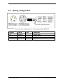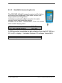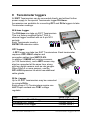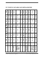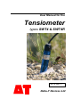
1
User Manual for the Tensiometer types SWT4 & SWT4R SWT4-UM-3.1 Delta-T Devices Ltd Notices Copyright All rights reserved. Under the copyright laws, this manual may not be copied, in whole or in part, without the written consent of Delta-T Devices Ltd. and UMS GmbH. Under the law, copying includes translation into another language. Copyright © 2009 Delta-T Devices Limited © 2009 UMS GmbH CE conformity The sensors described in this document are CE marked by the manufacturer. Design changes Delta-T Devices Ltd reserves the right to change the designs and specifications of its products at any time without prior notice. SWT4 User Manual, Version: 3.1 Oct 2009 Strictly observe rules for disposal of equipment containing electronics. Within the EU: disposal through municipal waste prohibited - return electronic parts to your local distributor Delta-T Devices Ltd 130 Low Road, Burwell CAMBRIDGE CB25 0EJ U.K. 2/52 Tel: +44 1638 742922 Fax: +44 1638 743155 e-mail: [email protected] [email protected] web: http://www.delta-t.co.uk Table of contents User Manual for the 1 Tensiometer 1 Notices 2 1 Introduction 1.1 1.2 1.3 1.4 1.5 1.6 1.6.1 1.6.2 1.6.3 1.7 2 5 Safety instructions and warnings Unpacking Foreword Guarantee Durability SWT4 and SWT4R Soils and soil water Intended use Types Quick Start 5 6 6 6 6 7 7 7 7 8 Sensor Description 12 2.1 Parts 2.1.1 Body and shaft 2.1.2 Pressure sensor 2.1.3 Reference air pressure 2.1.4 The ceramic cup 2.2 External refilling (SWT4R only) 2.3 Analog output signals 12 12 12 12 13 13 14 3 15 Installation 3.1 3.1.1 3.1.2 3.1.3 3.1.4 3.1.5 3.1.6 3.1.7 3.2 3.2.1 3.2.2 3.3 3.4 3.4.1 3.5 3.5.1 3.5.2 3.5.3 3.5.4 Advance planning Selecting the measuring site Number of Tensiometers per level Extent of the site Protection of refilling tubes (SWT4R only) Use of Tube Jackets and Conduit Ideal conditions for installation Documentation Selecting the installation angle "Vertical" tilting downwards (SWT4R only) "Horizontal" tilting upwards (SWT4R only) Installation procedure Offset correction for non horizontal installations How to measure the zero offset of a tilted tensiometer Connecting SWT4 and SWT4R Spot reading with the SWT-MR (Infield7) Connecting cables Connection to a data logger Connection to Delta-T Loggers 4 Service and maintenance SWT4 User Manual v3.1 15 15 15 15 16 16 17 17 18 18 18 19 21 22 23 23 23 23 24 26 3 4.1 Refilling 4.1.1 When do Tensiometers need to be refilled? 4.1.2 Refilling in the lab 4.1.3 Refilling in the field (SWT4R only) 4.1.4 Refilling with a vacuum pump (SWT4R only) 4.2 Testing 4.2.1 Calibration 4.2.2 Check the Offset 26 26 27 29 30 33 33 33 5 34 Protecting the measuring site 5.1 5.2 5.3 5.3.1 5.3.2 5.4 6 6.1 6.2 6.3 6.4 6.5 Theft and vandalism Cable protection Frost Protection against frost Emptying SWT4 or SWT4R Lightning protection and grounding 34 34 34 34 35 35 Useful notes 37 Maximum measuring range and data interpretation Temperature influences Vapor pressure influence Osmotic effect Using Tensiometers as a piezometer 37 39 39 39 40 7 Troubleshooting 40 8 Appendix 41 8.1 Technical specifications 8.2 Wiring configuration 8.3 Accessories 8.3.1 Connecting and extension cables 8.3.2 Handheld measuring device 41 42 43 43 44 9 45 Tensiometer loggers 9.1.1 Voltage regulators 9.1.2 Refill kits 9.1.3 Tensiometer augers 9.2 Units for soil water and matrix potentials 46 46 47 48 10 Technical Support 49 Terms and Conditions of sale Service and Spares Technical Support Contact Details 49 50 50 50 11 Index 51 4 SWT4 User Manual v3.1 1 Introduction 1.1 Safety instructions and warnings Electrical installations must comply with the safety and EMC requirements of the country in which the system is to be used. Please note that any damage caused by handling errors are out of our control and therefore are not covered by guarantee. Tensiometers are instruments for measuring the soil water tension, and soil water pressure and are designed for this purpose only. Please pay attention to the following possible causes of risk: Lightning: Long cables act as antennas and might conduct surge voltage in case of lightning stroke – this might damage sensors and instruments. Frost: Tensiometers are filled with water and therefore are sensitive to frost! Protect Tensiometers from frost at any time. Never leave Tensiometers over night inside a cabin or car when freezing temperatures might occur! Tensiometers are not usually damaged when the cup is installed in a frost-free soil horizon. Excess pressure: The maximum non destructive pressure is 300 kPa = 3 bar = 3000 hPa. Higher pressures - which might occur, for example, during insertion in wet clayey soils, whilst measuring shear force, or during refilling and reassembly - will destroy the pressure sensor! Electronic installation: Any electrical installations must be executed by qualified personnel. Ceramic cup: Do not touch the cup with your fingers. Grease, sweat or soap residues will influence the ceramic's hydrophilic performance. SWT4 User Manual v3.1 Introduction 5 1.2 Unpacking The SWT4 or SWT4R includes: Tensiometer, calibrated and filled, with 4-pin plug M12/IP67 with plug cap This manual Plastic bottle protecting the ceramic cup (must be half-filled with water to keep the cup wet) Rubber shaft water protection disk Calibration certificate with each order for conversion of electrical to physical values With type SWT4R: a refill syringe SWT4 and SWT4R are filled and ready for installation when supplied. See also “Accessories” on page 43. 1.3 Foreword Measuring systems must be reliable and durable and should require a minimum of maintenance to achieve target-oriented results and keep the servicing low. Moreover, the success of any technical system directly depends on it being used correctly. At the beginning of a measuring task or research project the target, all effective values and the surrounding conditions should be defined. This then leads to the requirements for the scientific and technical project management which describes all quality related processes and decides the methods to be used, the technical and measurement tools, the verification of the results and the modeling. The continuously optimized correlation of all segments and its quality assurance are decisive for the final success of a project. We wish you good success with your projects. Please do not hesitate to contact us for further support and information. 1.4 Guarantee See Terms and Conditions of Sale on page 49. 1.5 Durability The nominal lifespan for outdoor usage is 10 years, but protection against UV-radiation and frost as well as proper and careful usage substantially extends the lifespan. 6 Introduction SWT4 User Manual v3.1 1.6 1.6.1 SWT4 and SWT4R Soils and soil water All water movement in soil is directly dependant on the soil water tension, because water, both in the soil and on the surface, will always move from a point of higher potential to a point of lower potential. The majority of soil water flow take place in response to small water tensions. Only Tensiometers allow the direct and precise measurement of these small tensions. Natural soils in the ground are heterogeneous. It is not just precipitation and evaporation that matter, but also the soil texture, particle size distribution, cracks, compaction, roots and cavities. All these heterogeneities cause the soil water tension to vary. It is prudent therefore to have multiple measuring points, particularly in soil horizons close to the surface. 1.6.2 Intended use Tensiometers measure soil water tension – a measure of the soil matrix potential – which is the work the plant needs to do in order to extract water from a unit volume of the soil. These Tensiometers work from +100 kPa (water pressure) to -85 kPa (suction or soil water tension). If the soil gets drier than -85 kPa, the Tensiometer runs dry and must be refilled as soon as the soil is sufficiently moist again (see Fig 6.1). Soil water and Tensiometer water have contact through the ceramic which is porous and permeable to water. A wetted porous ceramic creates an ideal pore/water interface. The soil water tension is directly conducted to the pressure transducer which offers a continuous signal. The atmospheric reference pressure is provided through a membrane on the cable, a unique patented method. 1.6.3 Types The SWT4 is available in 2 versions: the standard SWT4 without refilling tubes, and the SWT4R with refilling tubes for refilling the Tensiometer in the field with a syringe. Separate refilling instructions for the SWT4R are provided in section 4. SWT4 User Manual v3.1 Introduction 7 1.7 Quick Start This section does not replace the rest of the user manual. It is only a summary. Please read the complete manual carefully before using the instrument, particularly Chapter 3 and 5! 1. Drilling the borehole Mark the required drilling depth both on auger and on Tensiometer shaft. Note: Installation depth = drilling depth / cos . For SWT4R: For installation from the soil surface, an installation angle of 25° to 65° from the vertical line is ideal for the optimal removal of air from the cup (Fig. 1a). For “horizontal” installation from a manhole the borehole should point upwards in an angle of 5° (Fig. 1b). 2. Slurrying the cup is only reasonable in clayey soils and only if the bore hole is larger than the ceramic cup (24 mm). In coarse sand or pebbly soils, a fine-pored slurry might create a water reservoir which slows down the response. With the special Tensiometer gouge auger type SWT4-AUG slurrying is unnecessary because of the accurate fit of the Tensiometer into the hole. 3. Take off the protective plastic bottle from the Tensiometer cup. Tilt and pull the bottle off carefully. If necessary, carefully turn it counterclockwise only! (as marked on the bottle) Turn the bottle counter-clockwise only when you remove the bottle but also when you reassemble the bottle (see arrow on bottle label). 4. Insert the SWT4 or SWT4R into the hole to the depth mark with constant gentle pressure and without using force. In clayey soils a dangerous overpressure might develop. So monitor the Tensiometers pressure with a type SWT-MR (INFIELD7) Manual Readout Unit or a data logger. Do not exceed -2 bar ( -200 kPa, -2000 hPa) during insertion. Do not turn the Tensiometer after it is inserted into the ground this might loosen the cup. 8 Introduction SWT4 User Manual v3.1 Note for SWT4R Tensiometers: Pay attention to the engraved black spot on the shaft’s top end that marks the position of the exit opening of the external filling inside the cup: a) Downwards installation: If the position of the cup will be lower than the end of the shaft, the black mark must exactly face up! The optimal installation angle is between 25° and 65°. b) Upwards installation: If the position of the cup will be higher than the end of the shaft, the black mark must exactly face down! The optimal installation angle is about 5°. Fig. 1a) Downwards installation Fig. 1b) Upwards installation 5. Push down the shaft water retaining disk to a position directly on the soil surface. 6. For SWT4R: Slide a thermal insulation tube over the capillary filling tubes. 7. If the plug is not connected right away leave the protective cover on the plug. Dirt will influence the impermeability and water tightness is only assured when the plug is kept clean. 8. Connect the Tensiometer signal wires to either a data logger or the SWT-MR/Infield7 See also: “Wiring Configuration” on page 42 GP1-PGA1 Quick Start Guide (for GP1 Logger users) LS2Win Software online help (for DL2e Logger users). SWT4 User Manual v3.1 Introduction 9 Please note: Especially in loamy, clayey soils a high pressure can occur just by inserting the SWT4 or SWT4R into the borehole. Thus, the pressure values should be continuously observed during installation with an SWT-MR/Infield7 Manual Readout Unit or a data logger. Keep it less than -200 kPa, i.e. -2000 hPa The less air left inside the cup and the better the soil's conductivity is, the faster the Tensiometer will respond to tension changes. If the soil is dryer than -90 kPa (-900 hPa), it does not make sense to refill the Tensiometer immediately. Wait until any Tensiometer that is installed in the next lower level again reaches the reading it had when the upper Tensiometer dried out. 10 Introduction SWT4 User Manual v3.1 External syringe refilling (SWT4R only) Installed SWT4R can be refilled or ventilated through the two capillary tubes (stainless steel) without being removed from the soil. The tubes can be extended. With the supplied refilling syringe a measuring range of at least -80 kPa can be assured. With the special Refilling Kit SWT4-RK2 a range of -85 kPa can be assured. Reference air pressure The reference atmospheric air pressure is conducted to the pressure transducer via the water impermeable (white) Teflon membrane and through the cable. The membrane must always have contact to the air and should never be submersed into water. Cable gland (IP67) SWT4 and SWT4R can be completely buried if required. If buried, cables and tubes should be protected. Special cable glands are available for making tight seal to with plastic protection tube for the cable - see Accessories on page 43. Transparent acrylic shaft One-piece shafts from 10 cm to 200 cm are available. Shafts over 200 cm are divided with threaded adapter and are available up to nearly any length. Sensor body with electronic The incorporated piezoelectric pressure sensor measures the soil water tension against atmospheric pressure. Direct connection to any power supply: e.g. battery, TVB1 or TVB-M, power supply unit Pressure transducer Position of the pressure sensor opening, position of the temperature sensor and the ventilation tube. High grade porous ceramic cup Filled with degassed water, with refilling tube. SWT4 User Manual v3.1 Introduction 11 2 Sensor Description 2.1 Parts 2.1.1 Body and shaft The pressure transducer is integrated in the sensor body. The electronics are completely sealed and thus well protected against moisture. The shaft is made of transparent blue acrylic plastic and has a very high durability and impact resistance. 2.1.2 Pressure sensor The piezoelectric pressure sensor measures the soil water tension against the atmospheric pressure. Atmospheric pressure is conducted via a white air-permeable membrane on the cable, through the cable, to the reference side of the pressure sensor. The maximum permissible, i.e. non-destructive, pressure is 3 bar (300 kPa, 3000 hPa). Higher pressure will damage the sensor and absolutely must be avoided! High pressures can appear for example when cup and sensor are reassembled, when inserted in wet, clayey soils, or in tri-axial vessels used for measuring shear forces. 2.1.3 Reference air pressure The reference atmospheric air pressure is conducted to the pressure transducer via the air permeable (white) Teflon membrane in-line in the cable. The membrane does not absorb water. Water will not pass through the membrane into the cable, but condenation inside the cable can leave the cable through the membrane. The white membrane on the cable must always have contact to air and should never be submersed under water. 12 Sensor Description SWT4 User Manual v3.1 2.1.4 The ceramic cup To transfer the soil water tension as a negative pressure into the Tensiometer, a semi-permeable barrier is required. This must have good mechanical stability, be permeable to water and impermeable to gas (when wet). The Tensiometer cup consists of ceramic Al2O3 sintered aluminium. A special manufacturing process guarantees homogeneous porosity with good water conductivity and very high hardness. Compared to conventional porous ceramic the cup is much more durable. The bubble point is at least 1500 kPa (15 bar, 15,000 hPa). If the soil is dryer than -1500 kPa air can enter, the negative pressure inside the cup decreases, and the readings go down to 0 kPa. With these characteristics this material has outstanding suitability to work as the semi-permeable diaphragm for Tensiometers. The cup has a lifetime guarantee against breakage. Ceramic cup: Do not touch the cup with your fingers. Grease, sweat or soap residues will influence the ceramic's hydrophilic performance. 2.2 External refilling (SWT4R only) The SWT4R is equipped with 2 stainless-steel capillary tubes which are led through the cable gland and the shaft. Each one has an opening that ends inside the ceramic cup. This allows easy refilling of the SWT4R while it remains installed in the ground. Tube 1 ends at the very tip of the cup, tube 2 ends next to the 1 pressure transducer opening. Outside, both tubes are connected together with a short rubber tube. Any air bubbles will ascend and accumulate either in the ceramic’s tip around tube 1 (upwards installation angle) or next to opening 2 (downwards installation angle). Accordingly the air is removed either through tube 1 or 2 (please see chapter 3.2). 2 SWT4 User Manual v3.1 Sensor Description 13 Black mark on tube 2.3 Analog output signals The pressure transducer offers an linear output signal. As the output signal directly depends on the supply voltage, the supply voltage needs to be constant and stabilized. As the pressure transducer is a Wheatstone full bridge, it has to be connected in a certain way. See also Connecting SWT4 and SWT4R on page 23 and the user manual for your display unit or data-logger before connection. 14 Sensor Description SWT4 User Manual v3.1 3 Installation 3.1 Advance planning 3.1.1 Selecting the measuring site The installation spot should be representative of the soil horizon! Therefore, in heterogeneous soils, soil samples should be taken and classified before or during installation. On farmed sites with vegetation, root spreading and root growth during the measuring period must be considered. Fine roots will grow around the Tensiometer cup as this is a poor but still secure source of water. Therefore, avoid the root zone or move the Tensiometer from time to time depending on the root growth. Disturbing effects like the edge of a field, slopes or hollows must be avoided or taken into account when interpreting the data. 3.1.2 Number of Tensiometers per level The deeper the level, the less the variation is in water potential. In lower sandy or pebbly horizons just one Tensiometer per depth is sufficient. Close to the surface about 3 Tensiometers per level are recommended. Guiding principle: More heterogeneous sites and soil structures require a higher number of Tensiometers. 3.1.3 Extent of the site A large number of well-spaced samples will help reduce sampling errors in heterogeneous soils. To obtain a differential description of the soil water situation, at least 2 Tensiometers are recommended per horizon, one in the upper and one in the lower level. The maximum recommended cable length for SWT4 and SWT4R is 40 meters. Accuracy: long cables reduce the accuracy. Lightning: cables act as antennas and should always be as short as possible. SWT4 User Manual v3.1 Installation 15 3.1.4 Protection of refilling tubes (SWT4R only) A recent study by Prof. Wolfgang Durner showed that refilling tubes must be protected from heating up and solar radiation. If a bubble grows inside a refilling tube, temperature changes will lead to an expansion of the air, resulting in a variation of the reading. Therefore, refilling tubes should be as short as possible and should be thermally protected, either by providing an insulating protection or by burying the tubes. Thermal effect: As long as the Tensiometer and its tubes are freshly and completely filled it will work perfectly. Any air trapped inside the upper parts of the tube will expand when heated up by solar energy. This causes a drop of the water tension and some water will flow from the cup into the ground. Thus, readings will fluctuate around the actual reading during solar radiation, specially with low water potentials. Furthermore, under permanent solar exposure the tubes get sticky and brownish. Thermal inuslation tube Slide the supplied thermal insulation tube over the shaft end and the refilling tubes as shown in above photo! 3.1.5 Use of Tube Jackets and Conduit Tube Jackets: These are useful with shafts longer than 2 m, in pebbly soils or gravel, and for horizontal installations from inside a well or pit hole. The tube jacket should end 30 to 50 cm away from the cup so that no leakage or condensation is conducted to the cup. The inner diameter of the jacket should be at least 35 mm. 16 Installation Tube Jackets SWT4 User Manual v3.1 Conduit: This pictures shows an example of the use of flexible cable conduit (trunking) to protect the tensiometer cables. 3.1.6 Ideal conditions for installation For the installation of Tensiometers, the ideal conditions are: Frost-free soil. Wet coarse clay or loess (wind deposited soil). Low gravel content. The more gravel in a soil the more often the drilling has to be repeated to reach the required depth. 3.1.7 Documentation For every measuring spot you should: Measure out the position where the pressure sensor will be placed. (A must for installations below the ground surface). Take documentary photos before, during and after installation. Save a soil sample. Write down installation depth and angle with each sensor identification (serial number). Mark all connecting cables with the corresponding sensor identification, serial number or logger channel on each end. Clip-on numbered rings are available as an accessory. Contact Delta-T for more information. SWT4 User Manual v3.1 Installation 17 3.2 Selecting the installation angle Ideally, a Tensiometer installation should not disturb the flow of water. To prevent the preferential flow of water along the shaft Tensiometers should be installed at an angle. 3.2.1 "Vertical" tilting downwards (SWT4R only) When installed from the surface, an angle of 25° to 65° from the vertical is optimal for refilling. In an absolutely vertical position air bubbles might hide inside the edges of the cup adapter. Still, they could be removed completely with a hand vacuum pump (contact Delta-T for details). In this position, the refilling tube is the shorter stainless steel tube with the black mark. Water is injected Into this tube for refilling. Before inserting the Tensiometer, orient the shaft so the black mark near the shaft end points upwards. Do not rotate the shaft after it is inserted into the ground as this might loosen the cup. 3.2.2 "Horizontal" tilting upwards (SWT4R only) When installed horizontally from inside a well or pit hole, the Tensiometer must point upwards! This means the cup is in a higher position than the end of the shaft. An upward angle of approx. 5° is ideal for refilling. Note that now de-airing and refilling tube are switched: the refilling tube is the longer stainless steel tube without the black mark. Water is injected into this tube for refilling. Before inserting the Tensiometer, turn the shaft so the black mark near the shaft end points downwards. Do not turn the shaft after it is inserted into the ground as this might loosen the cup. Note that with a horizontal installation the (optional) filling indicator will not react until the cup is almost empty. 18 Installation SWT4 User Manual v3.1 3.3 Installation procedure For the installation of the Tensiometer in the field the following tools are required: Tensiometer auger with diameter 25 mm, ideally the SWT4-AUG Gouge Auger with shaped blade tip. Rule, spirit level, angle gauge, marker pen. Notebook, camera for documentation of site and soil profile. Perhaps PE-plastic bags for taking soil samples from the site. Thermal insulation tubes for installations from soil surface. Cable protection conduit. Tube Jackets if required (inner diameter > 35 mm). Please observe the following notes: Do not touch the cup with your fingers. The ceramic should not have contact with grease or soap as this will influence the hydrophilic performance. Do not leave the cup in air for more than 5 minutes as Tensiometer water will evaporate and the Tensiometer will need to be refilled. Procedure: 1. Mark the required drilling depth on auger and Tensiometer shaft. The reference point is the center of the cup. Drill a hole with the desired depth on the chosen measuring spot. Auger in steps. Take care when drilling the last 20 cm, remove and save this soil. Water will not run along the shaft if the Tensiometer is installed in an angle because the water will drain into the soil before it reaches the cup. Read the chapter "Selecting the installation angle" for the best installation angle on page 18. 2. When using augers with a diameter of over 25 mm, mix a paste of water and crumbled soil material taken out of the borehole. Fill the paste into the bottom area of the borehole by using a simple pipe with outer diameter 2 cm. SWT4 User Manual v3.1 Installation 19 3. Now remove the protective plastic bottle from the Tensiometer cup. Important: Only turn the bottle counter-clockwise when taking the bottle off - and also when putting it back on again! Save the plastic bottles: Do not store the Tensiometer without the protective plastic bottle since the cup empties quickly! The bottle must be filled with some water for storage! 4. Connect the Tensiometer to a readout unit. Carefully insert the SWT4/SWT4R into the borehole up to the stop while continuously observing the pressure signal. Do not use any force. Do not hit the Tensiometer - this may damage cup and pressure sensor. Especially in clayey soils the pressure reading must be monitored as high pressures might build up! The pressure should not exceed 200 kPa (2000 hPa) (because >300 kPa is fatal!) Note for SWT4R Tensiometers: Important: Pay attention to the engraved black spot on the shaft’s top end that marks the position of the exit opening of the external filling inside the cup: a) Downward tilting installations: If the position of the cup will be lower than the end of the shaft, the black mark must exactly face up! b) Upward tilting installations: If the position of the cup will be higher than the end of the shaft, the black mark must exactly face down! Fig. 3a) Downwards installation 20 Installation Fig. 3b) Upwards installation SWT4 User Manual v3.1 5. Press the soil surface with your boots gently to the shaft to close the gap. 6. Push the shaft water protection disk down to cover the soil surface. This prevents water from running down into the borehole along the shaft. 7. Leave the protective plastic cover on the plug whenever the plug is not connected! 8. Connect the signal cables as described in the chapter Connecting the SWT4 or SWT4R on page 23. 9. The Tensiometer will respond to changes in the soil water tension faster if there is no air inside the system and the soil water conductivity is high. 10. Write down the serial number, position, installation angle and depth. 11. Slide the supplied thermal insulation tube over the shaft end and the refilling tubes. Bend the signal cable and lead it back through the thermal tube. 12. Protect the cables against rodent bites. Lead the cables through plastic pipes or use the plastic protection tubes, conduit or trunking. Contact Delta-T for details. 3.4 Offset correction for non horizontal installations The pressure transducer is calibrated without a cup. Thus, no compensation is required for horizontal installations. If a SWT4 or SWT4R is installed in a non horizontal position, the vertical water column draws on the pressure sensor and causes an offset shift. Compensate the offset: by calculation, by entering the installation angle in the Infield7 (SWT-MR) for spot readings, in the configuration of a data logger by setting an offset. The middle of the cup is regarded to be the measuring level. The correction is largest for a vertical water column (at 0o) and varies as the cosine of the installation angle, as shown on the table below. In an absolutely horizontal position the offset is zero. SWT4 User Manual v3.1 Installation 21 Example 1:Using A 5 cm vertical column of water below the pressure sensor will create an 0.5 kPa offset. This means that when the soil water tension is 0 kPa the sensor will indicate -0.5 kPa. Table showing the offset correction when a 5 cm column of water is tilted at various angles: Angle to vertical line Offset correction in [kPa] Angle to vertical line Offset correction in [kPa] 0° 10° 15° 20° +0.5 +0.49 +0.48 +0.47 45° 60° 70° 75° +0.35 +0.25 +1.7 +1.3 25° +0.45 30° +0.43 80° +0.9 90° 0 The offset is entered as + in your logger if you regard the soil water tension to be negative (0 ... -85 kPa). 3.4.1 How to measure the zero offset of a tilted tensiometer As an alternative to using the table above, if the tensiometer is to be installed pointing downwards, submerge it up to one half the height of the ceramic cup in a beaker of water, tilting the tensiometer to the desired angle. The data logger reading in mV now represents 0kPa water tension at that angle, giving you the zero offset correction directly. 22 Installation SWT4 User Manual v3.1 3.5 3.5.1 Connecting SWT4 and SWT4R Spot reading with the SWT-MR (Infield7) SWT4 and SWT4R are fitted with a 4-pin plug. The plug can be connected directly to an SWT-MR handheld measuring device for taking spot readings of the soil water tension. This displays and stores the soil water tension. 3.5.2 Connecting cables Connecting and extension cables are required for connecting SWT4 and SWT4R to a data logger or other data acquisition device. Find cables in the chapter “Accessories” on page 43. 3.5.3 Connection to a data logger Delta-T Logger users: see Connection to Delta-T Loggers on page 24. The pressure transducer is a non-amplified full Wheatstone bridge circuit which is calibrated at 10.6 VDC. It requires a stabilized power supply. Some logger types can measure bridge circuits directly, other loggers require additional measures, because the signal minus and the supply minus do not have the same ground. If supplied with exactly 10.6 V (i.e. supply minus = 0 V and supply plus = 10.6 V) the Tensiometer output signal range is between +3.2 V (min.) and +6.8 V (max.) relative to the power supply minus. This may be outside the common mode range of some loggers. Other supply voltage ranges are permissable, but the output signal range has to be recalculated. The supply voltage must be constant and stabilized. If the Tensiometer is not permanently powered, the warm-up period before a measurement is normally 1 second. It should be no greater than 10 seconds. The Tensiometer plug should be covered with the protective cover (as supplied) when not connected to a cable. The supply voltage must not exceed 18 VDC. SWT4 User Manual v3.1 Installation 23 3.5.4 Connection to Delta-T Loggers All SWT Tensiometers can be connected directly and without further power supply to the special Tensiometer logger DL6-tens. Accessories are available for converting GP1 and DL2e loggers to take Tensiometer readings. DL6-tens Logger The DL6-tens can take six SWT Tensiometers. This is a standard Delta-T DL6 6-channel logger modified with six 4-pin M12 sockets. Each Tensiometer needs a SWTEC-20 extension cable. GP1 Logger A GP1 logger can take two SWT Tensiometers. Each tensiometer requires a GP1-PBA1 adapter and connection cables type SWTCC-XX . In addition 2 SM200 soil moisture sensors, (or 10K thermistors), and a WET sensor may also be connected at the same time, along with two digital sensors such as rain gauges. When fitting 5 or more sensors use the GP1-LID2 expansion lid which has additional cable glands. DL2e Logger Up to 60 SWT tensiometers may be connected to a single DL2e. Each group of 15 Tensiometers require one LAC1 input card. In addition, each group of 15 require one TVB1 voltage regulator (which itself requires a 12V supply from a 12V battery or mains powered power supply). 24 Installation SWT4 User Manual v3.1 TVB-M Voltage regulator for the DL2e Logger This regulated power supply is specially designed for powering Tensiometers SWT3, SWT4, SWT4R and SWT5 when connected to a DL2e logger. It provides a stabilised 10.6 V power supply, but with the supply minus at -5 V and supply plus at +5.6 V. This arrangement ensures the Tensiometer signals are less than 1 V. The TV-Batt itself requires power from a 12V battery or a mains to 12 V power converter. Each TVB-M module has screw terminals to power up to 15 Tensiometers. See also Voltage regulators on page 46 SWT4 User Manual v3.1 Installation 25 4 Service and maintenance 4.1 Refilling To assure a rapid and reliable measurement of the soil water tension, the cup must be filled possibly bubble-free with degassed water. After dry periods or periods with a large number of wet and drying out successions, the SWT4 or SWT4R must be refilled. The following items are required for all refilling methods: Syringe with valve (one supplied with each order) Degassed, de-ionized or distilled water Measuring device for checking the pressure signal Simple method to degas water: The best way to degas water is by using a syringe. Draw up water into the syringe until it is 2/3 filled. Close the valve or block the syringe with your finger. Now draw up the syringe as far as possible to create a vacuum inside. Rotate the syringe to create one big bubble. Remove your finger or open the valve and squeeze out the bubble. Repeat this procedure a few times. 4.1.1 When do Tensiometers need to be refilled? Tensiometers need to be refilled if: the curve of the readings apparently gets flatter (for example a rain event has no sharp peak but is round), the maximum of -85 kPa is not reached anymore. Refilling is only reasonable if the soil is moister than -90 kPa, or as soon as a Tensiometer installed in a lower level shows wetter readings than the reading at which the upper Tensiometer stopped working... If the soil gets dryer than -85 kPa, the readings will remain constant at the vapor pressure of water (for example: the reading will be 92.7 kPa at 20°C and atmospheric pressure of 95 kPa). By diffusion and slight leakage the reading will slowly drop within months. 26 Service and maintenance SWT4 User Manual v3.1 If the soil dries out more than -1500 kPa (-15 bar), the negative pressure will drop much faster as air will enter the cup. 4.1.2 Refilling in the lab To reach the optimal measuring range of -90 kPa Tensiometers should be refilled in the laboratory using the refill kit. 1) Set up the refilling kit and connect the vacuum pump as shown in fig. 4.1. The pump should achieve at least 0,8 kPa against vacuum. Use distilled or de-ionized water which does not necessarily have to be degassed when a pump is used. Vacuum gauge Adaptor for sensor body Adaptor for ceramic cup Connect to pump Fig. 4.1: Laboratory refill kit SWT4-RK2 2) Unscrew the cup in clockwise direction and empty it. Do not touch the ceramic cup with your fingers. Wrap a clean towel or paper towels around the cup! The pressure sensor diaphragm is inside the small hole on the pressure sensor body. It is very sensitive and must never be touched! It can be destroyed even by the slightest contact! No contamination should get on to the sealing and gasket. 3) If the cup is dry it should be placed in a beaker filled with distilled water for several hours or overnight. Initially there should be no water inside the cup! Place the empty cup into the beaker in an upright position, with the external water level reaching no higher than 2/3 of the cup. SWT4 User Manual v3.1 Service and maintenance 27 4) 5) 6) 7) Warning! If the cup is filled with water and water intrudes from both inside and outside, cavities of air will be trapped inside the ceramic. Insert the saturated but empty cup to the adapter and connect it to the degassing device. Place the cup in water in an upright position with the external water level reaching up to 2/3 of the cup. Half fill the second adapter capsule with water and insert the sensor body. Connect the adapter to the degassing device as well. Now start the vacuum pump. With well-saturated cups, the procedure will take 1 to 2 hours. From time to time knock on cup and sensor body to loosen bubbles. Degassing is complete when no air bubbles ascend from ceramic and body and the cup is completely filled with water. Before screwing together cup and sensor body connect the sensor to a measuring device to observe the pressure signal. Warning! Do not exceed 2 bar, as 3 bar will destroy the sensor! Hold the cup in an upright position, fill it completely and with an overlapping meniscus of water. Carefully and slowly screw the cup on the sensor body. Allow the excess water to escape. Make sure that no bubbles are enclosed. 8) Fix the Tensiometer at an angle so the cup is pointing downwards, and the black mark on the shaft is on top. 9) Degas the water in the syringe as described above and connect it to the refilling tube (it has a black mark). Do not bend the rubber tube. Carefully inject water into the refilling tube until no bubbles come out of the de-airing tube. Inject at least 25 ml. Check the pressure all the time! 10) Remove the syringe and re-connect the rubber tube to the open refilling tube. 28 Service and maintenance SWT4 User Manual v3.1 4.1.3 Refilling in the field (SWT4R only) SWT4R Tensiometers can be refilled with the 50 ml syringe (supplied) through the stainless steel tubes without removing them from the soil. If the refilling tubes have a total length of 5 meters or more use the handoperated vacuum pump – see section 4.1.4. With this method a range of at least -80 kPa can be measured. Fig. 4.2 Downward tilted installation – the marked tube is the refilling tube, the unmarked tube the de-airing tube Fig. 4.3 Upwards tilted installation – the marked tube is the de-airing tube, the unmarked tube the refilling tube SWT4 User Manual v3.1 Service and maintenance 29 Procedure (see fig. 4.2 & 4.3): 1. Connect the SWT4R to the measuring device and keep an eye on the pressure signal all the time. 2. Two steel capillary tubes come out from the SWT4R shaft: the refilling tube and the de-airing tube. In a downwards tilting installations the marked tube is the refilling tube, in an upwards installation the unmarked tube is the refilling tube. Pull off the rubber tube from the refilling tube. 3. Degas the water inside the syringe as described above. 4. Connect the syringe to the refilling tube. 5. Carefully inject water into the refilling tube until no bubbles come out of the de-airing tube. Inject at least 25 ml. Check the pressure all the time! 6. Remove the syringe. Put a drop of water on the ends of both the rubber and steel tubes – and then connect them together. 4.1.4 Refilling with a vacuum pump (SWT4R only) To achieve the maximum possible measuring range Tensiometers can be completely degassed using a vacuum pump. This method can be applied for installed Tensiometers at any installation angle as well as for Tensiometers not yet installed. For refilling tubes longer than 5 meter this method should always be used. The refill kit SWT4-FRK2 includes all required tools: hand-operated vacuum pump, vacuum bottle with tube and syringe with valve. Fig. 4.4 External refill kit SWT4-FRK2 for the SWT4R 30 Service and maintenance SWT4 User Manual v3.1 Fig. 4.5 Downwards installation – the marked tube is the refilling tube, the unmarked tube the de-airing tube Fig. 4.6 Upwards installation – the marked tube is the de-airing tube, the unmarked tube the refilling tube Procedure (see Fig. 5.4 & 5.5): 1. Connect the SWT4R to the measuring device and keep an eye on the pressure signal all the time. 2. In a downwards tilting installation the marked tube is the refilling tube. In an upwards installation the unmarked tube is the refilling tube. Pull off the rubber tube from the refilling tube. 3. Degas the water inside the syringe as described above. Connect the syringe to the refilling tube and close the valve! 4. Connect vacuum bottle and de-airing tube. Using the vacuum pump, evacuate the bottle to the maximum possible vacuum. This will enlarge the remaining bubble inside the cup. SWT4 User Manual v3.1 Service and maintenance 31 5. Now briefly open and close the valve at the syringe a few times: water is drawn into the Tensiometer while at the same time the air bubble is sucked into the vacuum bottle. Repeat this 2 or 3 times until no more bubbles come out. 6. Close the valve of the vacuum bottle and remove the bottle. Inject 5 ml of water from the syringe into the refilling tube. Remove the syringe. Put a drop of water on the end of both the rubber and steel tubes and connect them together. 32 Service and maintenance SWT4 User Manual v3.1 4.2 Testing 4.2.1 Calibration When delivered Tensiometers are calibrated with an offset of 0 hPa (when lying horizontally) and a linear response. The offset of the pressure transducer has a minimal drift over the years. Therefore, we recommend you check sensors once a year and re-calibrate them every two years. Return the Tensiometers to Delta-T for recalibration, or contact us for details about available calibration accessories. 4.2.2 Check the Offset There are two ways to check the offset. 1. Connect the Tensiometer to a readout device. Fill the beaker with distilled or de-ionized water and immerse the ceramic cup to a depth of 7.5 cm. Wait until the reading is stable. If there are bubbles inside the cup this might take a while. The reading now should be 0 kPa. 2. To check the zero-point more precisely unscrew the cup. Shake the pressure sensor to remove water from the pressure transducer hole. The offset is acceptable when the reading is between -0.5 and +0.5 kPa. The pressure sensor diaphragm is inside the small hole on the pressure sensor body. It is very sensitive and must never be touched! It can be destroyed even by slightest contact! No contamination should get on the sealing and gasket. Before reassembling cup and sensor body carry out the degassing procedure (see chapter 4.1.2 "Refilling in the lab" on page 27). For testing the gain a calibration kit is required. Contact Delta-T for details SWT4 User Manual v3.1 Service and maintenance 33 5 Protecting the measuring site 5.1 Theft and vandalism The site should be protected against theft and vandalism as well as against any farming or field work. Therefore, the site should be fenced and signposts could give information about the purpose of the site. 5.2 Cable protection Cables should be protected against rodents with plastic protection tubes. Contact Delta-T for further information. 5.3 5.3.1 Frost Protection against frost Tensiometers are filled with water and can be damaged by frost. Do not store filled Tensiometer at temperatures below -5°C. Do not leave filled Tensiometers overnight in your car, in a measuring hut, etc. Do not fill the Tensiometers with Ethanol, as this is corrosive to some materials (i. e. PMMA) and will destroy these. Also it is not recommended to fill the Tensiometers with Decalin, monoethylene-glycol, di-ethylene-glycol, etc. These could harm any of the materials, destroy the ceramic cup or leak into the soil. SWT4 and SWT4R Tensiometers may remain installed during the winter if the cup is below 20 cm. Then the frost will enter the cup slowly without damaging the pressure sensor. The reading will jump to a constant value. After unfreezing the Tensiometer will continue to work. But as this depends on the climate of your region, please contact Delta-T if you intend to install Tensiometers in extreme temperature zones. 34 Protecting the measuring site SWT4 User Manual v3.1 5.3.2 Emptying SWT4 or SWT4R Also read chapter 4.1. SWT4R Tensiometers: 1) Remove the connecting rubber tube from the refilling tube. In a downwards installation the refilling tube is the marked tube, in an upwards installation the refilling tube is the unmarked tube. 2) Connect the empty syringe to the refilling tube and completely suck out the Tensiometer water. 3) Re-connect rubber tubes and filling tube. SWT4 Tensiometer, if installed within the depth of frost penetration, must be removed and stored in a frost-free place. 5.4 Lightning protection and grounding In-the-field measuring equipment is always susceptible to electrical surge. Our equipment is protected against over-voltage and wrong polarity as far as this is technically achievable. There never can be total lightning protection. Lighting strikes are unpredictable and vary significantly with region, voltage and destructiveness. Proper lightning protection has to be considered whenever a system with several sensors and loggers is installed. Passive lightning protection measures would comprise one or more grounding rods, preferably with ground water contact, but without (!) an electrical connection to the measuring system. With an active lightning protection each sensor and the logger are equipped with an individual grounded surge protection module. Unfortunately, these are very expensive. Please contact Delta-T or your distributor for assistance about integrating SWT4 or SWT4R into your measurement system. SWT4 User Manual v3.1 Protecting the measuring site 35 General recommendations for lightning protection and grounding for stations with battery power First step Recommendations for lightning protection on masts Recommendations for lightning protection of enclosures System protection of stations with enclosure and mast Lightning protection with grounding rods Measure the distances between sensor positions, data acquisition etc. to get to know the potential levels 2 or 3 meter masts can be equipped with a lightning rod which is installed on top of the mast, and a grounding rod which is clamped to the foot of the mast. This creates a zone of protection in a 45 degree angle cone around the tip Install surge protection devices in one corner of the measuring enclosure. All lines to and from the surge protection devices should not run parallel. Install a separate earth grid 50 cm below the soil surface to equalize variations in the ground potential between the sensors and the mast grounding rod . According to the standards the ground rod (diam. 25 mm) must be inserted into the ground for a minimum of 2,5 meters below the frost level, i. e. in general 3 meters. Cross shaped rods are less advisable for such low depths, but this depends on soil type, moisture or clay content, and distance between soil surface and ground water level. 36 Protecting the measuring site SWT4 User Manual v3.1 6 Useful notes 6.1 Maximum measuring range and data interpretation The measuring range of Tensiometers is limited by the boiling point of water. At a temperature of 20°C the boiling point is at 23 hPa over vacuum. So with 20°C and an atmospheric pressure of 950 hPa the Tensiometer cannot measure a tension below -927 hPa, even if the soils gets drier than that. The readings remain at a constant value (Fig. 6.1, between day 10 and 16). Interpretation Messwerte bis über 15readings bar nahe when der Typical behaviour of tensiometer Bodenoberfläche tension exceeds -15,000 hPa close to the surface Wasserspannung tension (hPa) Soil water 100000 10000 1000 100 Bodenwasserspannung Soil water tension Tensiometer reading Tensiometermesswert 10 1 0 2 4 6 8 10 12 14 16 18 20 Time Zeit Day Fig. 6.1: Tensiometer readings with tensions beyond -15,000 hPa If the soil dries to -15,000 hPa, the ceramic’s bubble point is reached. The water in the ceramic cup will run out quickly and the reading of the air-filled cup will go to zero (Fig. 6.1, day 16 to 19). SWT4 User Manual v3.1 Useful notes 37 If it rains before the soils reaches -15,000 hPa, the Tensiometer cup will suck up the soil water. However, the soil water includes dissolved gasses which will degas as soon as the soil dries again, increasing the tension. This will result in a poor response, the signal curve will get flatter and readings will only slowly adapt to the actual soil water tension. Depending on the size of the developed bubble, readings will get less close to the maximum (Fig 6.2, after day 20). Interpretation Messwerte unter 10 bar-10,000 in tieferenhPa Interpretation of readings below Bodenschichten Wasserspannung tension (hPa) Soil water 10000 1000 100 Bodenwasserspannung Soil water tension Tensiometer reading Tensiometermesswert 10 1 0 5 10 15 20 25 30 35 DayZeit Fig. 6.2 Tensiometer readings with tensions to -10, 000 hPa Other problems that can be recognized by checking the data: Soil water tension normally change only slowly. An erratic signal curve with many discontinuities could indicate, for example loose contacts, moisture in defective cables or plugs, poor power supply or a data logger malfunction. With SWT4R Tensiometers, unsteady signals can also be caused by solar radiation on the refilling tubes. To prevent this fit thermal insulation - see page 16. 38 Useful notes SWT4 User Manual v3.1 6.2 Temperature influences If the sensor is not powered continuously the voltage should be switched on for no longer than 10 seconds before a measurement. In this case, the self heating is negligible. The correlation of water tension to water content is temperature dependent. The influence is low at tensions of 0 to 10 kPa 0 … 0,6 kPa/K, but high for tensions over 100 kPa (1 bar, 1000 hPa): R T M ln o = Water tension R = Gas constant (8,31J/mol K) M = Molecular weight p = Vapor pressure po = Saturation vapor pressure at soil temperature (from Scheffler/Straub, Grigull) 6.3 Vapor pressure influence If the temperature of a soil with a constant water content rises from 20°C to 25°C the soil water tension is reduced for about 0.85 kPa due to the increased vapor pressure which opposes the water tension. Temperature in °C 4 10 16 20 25 30 50 70 Pressure change per Kelvin in [hPa] 0.6 0.9 1.2 1.5 1.9 2.5 7.2 14 6.4 Osmotic effect The ceramic has a pore size of r = 0,3 m and therefore cannot block ions. Thus, an influence of osmosis on the measurements is negligible because ion concentration differences are equalized quickly. If the SWT4 cup is dipped into a saturated NaCl solution the reading will be 1 kPa for a short moment, then it will drop to 0 kPa again. SWT4 User Manual v3.1 Useful notes 39 6.5 Using Tensiometers as a piezometer SWT4 or SWT4R can be used as a piezometer for measuring water overpressure. Calculate the height of the water level with: p pH 2O g h [hPa] and: h p pH 2O g pH2O .998205 kg/dm3, at 4°C: 1.0 kg/dm3. 2 2 [Pa] = N/m ; [N] = kg.m/s ; [Pa] = kg/(s2.m). A water column of 100 cm causes the following pressure: p [Pa= N/m2] = 998.205 kg/m3 x 9.81 m/s2 x 1m p = 9792.39 [kg/m3 x m/s2 x m ] = 9.792 kPa. Accordingly 10 kPa at 20°C indicate a water column of 102.15 cm. 7 Troubleshooting Please refer to the Delta-T website where you will find a regularly updated list of FAQs: http://www.delta-t.co.uk/product-faq-table.html?product2005092818915 40 Troubleshooting SWT4 User Manual v3.1 8 Appendix 8.1 Technical specifications Material and dimensions Ceramic material Ceramic dimensions Shaft material Sensor cable For shaft lengths < 120 cm For shaft lengths > 121 cm Plug Measuring range Pressure transducer Water tension Water level Output signal Pressure Accuracy Pressure transducer Power supply Supply voltage Vin Current consumption SWT4 User Manual v3.1 Al2O3 sinter, bubble point > 15 bar Length 60 mm, 24 mm Impact-proof PMMA, 25 mm Length 1.5 m from sensor body (effective length = 1.5 m minus shaft length) Length 2.3 m from sensor body (effective length = 2.3 m minus shaft length) Male 4-pin, thread M12, IP67 -100 kPa ... +100 kPa -85 kPa ... +100 kPa -85 kPa … 0 kPa 0 kPa … +100 kPa (electronically) (physically) (Tensiometer) (Piezometer) 85 mV = -85 kPa 0 mV = 0 kPa -100 mV = 100 kPa (Tensiometer) (Piezometer) ±0.5 kPa typ. 10.6 VDC (5 ... 15 VDC), stabilized 1.3 mA at 10.6 VDC Appendix 41 8.2 Wiring configuration Pin and wire configuration for connecting cables SWTCC Signal Wire Pin Function Vin VA-OUT+ A-OUT- brown blue white black 1 3 2 4 Supply plus Supply minus Signal plus Signal minus 42 Appendix SWT4 User Manual v3.1 8.3 Accessories 8.3.1 Connecting and extension cables Cables must be ordered additionally for each Tensiometer. 4-wire connecting cables SWTCC-xx are fitted with a female plug M12/IP67 and 12 cm wire end sleeves. Extension cables SWT-EXT-xx have one each male and female plug M12/IP67. Plugs are supplied with protective covers. Item 4-pin connection cables Length 1.5 m Length 5 m Length 10 m Length 20 m 4-pin extension cable Length 5 m Length 10 m Length 20 m Additional items Clip-on cable markers Plastic protection tubes Thermal insulation tubes SWT4 User Manual v3.1 Delta-T no. SWTCC-01 SWTCC-05 SWTCC-10 SWTCC-20 SWTEXT-05 SWTEXT-10 SWTEXT-20 Please contact Delta-T Please contact Delta-T Please contact Delta-T Appendix 43 8.3.2 Handheld measuring device The SWT-MR (Infield7) manual readout unit for taking and storing spot readings of soil water tension, soil temperature and filling status. Includes an automatic offset correction for water column height and installation angle. Suitable for all SWT Tensiometers. The unit comes with a small carrying case. Item SWT-MR manual readout Delta-T no, SWT-MR A USB converter is available for data collection from the SWT-MR to a PC via PC or laptop. It includes Windows PC software TensioVIEW. Item USB PC adapter for SWT-MR 44 Appendix Delta-T no, SWT-MR-USB SWT4 User Manual v3.1 9 Tensiometer loggers All SWT Tensiometers can be connected directly and without further power supply to the special Tensiometer logger DL6-tens. Accessories are available for converting GP1 and DL2e loggers to take Tensiometer readings. DL6-tens Logger The DL6-tens can take six SWT Tensiometers. This is a factory-modified Delta-T DL6 6channel logger modified with six 4-pin M12 sockets. Each Tensiometer needs a SWTEC-20 extension cable. GP1 Logger A GP1 logger can take two SWT Tensiometers. Each tensiometer requires a GP1-PBA1 adapter and connection cables type SWTCC-XX . In addition 2 SM200 soil moisture sensors, (or 10K thermistors), and a WET sensor may also be connected at the same time, along with two digital sensors such as rain gauges. When fitting 5 or more sensors use the GP1-LID2 expansion lid which has additional cable glands. DL2e Logger Up to 60 SWT tensiometers may be connected to a single DL2e. Each group of 15 Tensiometers require one LAC1 input cardand one TVB1 voltage regulator. Item 6-channel modified GL6 logger 2-channel GP1 logger 60 channel DL2e logger SWT4 User Manual v3.1 Delta-T no. Contact Delta-T Contact Delta-T Contact Delta-T Tensiometer loggers 45 9.1.1 Voltage regulators Tensiometer power supply unit for SWT3, SWT4, SWT5, fitted to a DL2e-logger extension frame (left), or as an open module (right). The regulated power supply itself can power up to 60 tensiometer. Each TVB1 logger frame has supply terminals for 15 Tensiometers. Contact Delta-T if you wish to fit more than 15 Tensiometers to one DL2e logger. Item TV-batt for DL2e logger TV-batt module only 9.1.2 Delta-T no. TVB1 TVB-M Refill kits SWT4-FRK2 Refill kit for externally refillable Tensiometers SWT4R, incl. hand operated vacuum pump, 250 ml bottle, refill syringe, tubes, valves. SWT4-LRK2 Laboratory refill kit for Tensiometers SWT4 & SWTT4R, incl. stand, clamps, adapter for SWT4 sensor body, 500 ml bottle, pressure gauge, tubes, beaker, refilling syringe and pliers. Item Refill kit for field use Laboratory refill kit Delta-T no. SWT4-FRK2 SWT4-LRK2 46 Tensiometer loggers SWT4 User Manual v3.1 All vacuum glass bottles are coated and implosion proof. 9.1.3 Tensiometer augers Tensiometer gouge auger with specially shaped blade. The tip of the blade has the same shape and diameter as the Tensiometer cup, so the Tensiometer fits tightly into the borehole. Thus, no slurrying of the cup is necessary. Set includes gouge auger and handle with hammering head. Item Auger with handle Extension rod, length 100 cm SWT4 User Manual v3.1 Delta-T no. SWT4-AUG Please ask Tensiometer loggers 47 48 Tensiometer loggers -1,000 -10,000 3 4 6 7 Air dry, air humidity dependant oven dry 980,665 98,066.5 14,709.9 9,806.6 980.7 834.5 323.6 98.1 9.8 cm H20 -10,000,000 9,806,650 -1,000,000 -100,000 -851 2.93 Standard Tensiometer range 5 -330 Field capacity 2.53 -15,000 -100 2.01 4.18 -10 1 Permanent wilting point hPa pF -1,000,000 -100,000 -10,000 -1,500 -1,000 -100 -85.1 -33 -10 -1 kPa = J/kg -1,000 -100 -10 -1.5 -1.0 -0.1 -0.085 -0.033 -0.01 -0.001 MPa -10,000 -1,000 -100 -15 -10 -1 -0.85 -0.33 -0.1 -0.01 bar -145,038 -14,504 -1,450.4 -219.52 -145.04 -14.504 -12.345 -4.9145 -1.4504 -0.1450 psi 0.0618 47.7632 92.8772 98.8977 99.2638 99.9261 99.9756 99.9926 99.9993 %RH 9.2 Units for soil water and matrix potentials SWT4 User Manual v3.1 10 Technical Support Terms and Conditions of sale Our Conditions of Sale (ref: COND: 1/07) set out Delta-T's legal obligations on these matters. The following paragraphs summarise Delta T's position but reference should always be made to the exact terms of our Conditions of Sale, which will prevail over the following explanation. Delta-T warrants that the goods will be free from defects arising out of the materials used or poor workmanship for a period of twelve months from the date of delivery. Delta-T shall be under no liability in respect of any defect arising from fair wear and tear, and the warranty does not cover damage through misuse or inexpert servicing, or other circumstances beyond their control. If the buyer experiences problems with the goods they shall notify Delta-T (or Delta-T’s local distributor) as soon as they become aware of such problem. Delta-T may rectify the problem by replacing faulty parts free of charge, or by repairing the goods free of charge at Delta-T's premises in the UK during the warranty period. If Delta-T requires that goods under warranty be returned to them from overseas for repair, Delta-T shall not be liable for the cost of carriage or for customs clearance in respect of such goods. However, Delta-T requires that such returns are discussed with them in advance and may at their discretion waive these charges. Delta-T shall not be liable to supply products free of charge or repair any goods where the products or goods in question have been discontinued or have become obsolete, although Delta-T will endeavour to remedy the buyer’s problem. Delta-T shall not be liable to the buyer for any consequential loss, damage or compensation whatsoever (whether caused by the negligence of the Delta-T, their employees or distributors or otherwise) which arise from the supply of the goods and/or services, or their use or resale by the buyer. Delta-T shall not be liable to the buyer by reason of any delay or failure to perform their obligations in relation to the goods and/or services if the delay or failure was due to any cause beyond the Delta-T’s reasonable control. SWT4 User Manual v3.1 Technical Support 49 Service and Spares Users in countries that have a Delta-T distributor or technical representative should contact them in the first instance. Spare parts for our own instruments can be supplied and can normally be despatched within a few working days of receiving an order. Spare parts and accessories for products not manufactured by Delta-T may have to be obtained from our supplier, and a certain amount of additional delay is inevitable. No goods or equipment should be returned to Delta-T without first obtaining the return authorisation from Delta-T or our distributor. On receipt of the goods at Delta-T you will be given a reference number. Always refer to this reference number in any subsequent correspondence. The goods will be inspected and you will be informed of the likely cost and delay. We normally expect to complete repairs within one or two weeks of receiving the equipment. However, if the equipment has to be forwarded to our original supplier for specialist repairs or recalibration, additional delays of a few weeks may be expected. For contact details see below. Technical Support Users in countries that have a Delta-T distributor or technical representative should contact them in the first instance. Technical Support is available on Delta-T products and systems. Your initial enquiry will be acknowledged immediately with a reference number. Make sure to quote the reference number subsequently so that we can easily trace any earlier correspondence. In your enquiry, always quote instrument serial numbers, software version numbers, and the approximate date and source of purchase where these are relevant. Contact Details Tech Support Team Delta-T Devices Ltd 130 Low Road, Burwell, Cambridge CB25 0EJ, U.K. 50 Technical Support Tel: +44 (0) 1638 742922 Fax: +44 (0) 1638 743155 email: [email protected] email: [email protected] web: www.delta-t.co.uk SWT4 User Manual v3.1 11 Index A E Accessories · 43 Accuracy · 41 atmospheric pressure · 12 augers · 47 Emptying · 35 C cable · 41 extension · 43 markers · 43 Cable protection · 34 cables · 23 Calibration · 33 CE conformity · 2 ceramic · 13 Ceramic · 41 clay · 17 Conditions of sale · 49 Conduit · 16 connection cables · 43 Contact Details · 50 Copyright · 2 Current consumption · 41 F Frost · 34 G GP1 Logger · 24 gravel · 17 grounding · 35 I Infield7 · 44 Installation · 15 procedure · 19 installation angle · 18 J D data logger · 23 Description · 12 DL2e Logger · 24 DL6-tens · 24, 45 Durability · 6 SWT4 User Manual v3.1 Jacket Tubes · 16 L Lightning protectio · 35 loess · 17 loggers · 45 51 M maintenance · 26 measuring range · 37 O Offset · 33 Offset correction · 21 Osmotic effect · 39 output · 14 P piezometer · 40 pressure · 12 problems · 38 Protection · 16 specifications · 41 SWT-MR · 44 T Technical Support · 49, 50 Temperature · 39 Terms · 49 Testing · 33 Thermal effect · 16 Troubleshooting · 40 tubes insulation · 43 protection · 43 U Units · 48 Unpacking · 6 USB converter · 44 Q V Quick start · 8 R range · 37, 41 refill kit · 30 Refill Kit SWT4-RK2 · 18 Refill kits · 46 refilling · 13 Refilling · 26 Vapor pressure · 39 Voltage regulator · 25 Voltage regulators · 46 voltage Vin · 41 W warnings · 5 Wiring · 42 S Z Service · 26, 50 soil sample · 17 soils · 7 Spares · 50 zero ffset How to check · 33 zero offset · 22 52 Index SWT4 User Manual v3.1