1
USER MANUAL
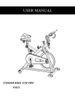
INOOR BIKE XTR600 Racing
WITH V-BELT/ SHOCK
Safety Instructions
*
*
Consult your physician before starting with any exercise program to receive advice on the optimal training.
Warning: incorrect/ excessive training can cause health injuries. Stop using the bike when feeling
uncomfortable.
*
*
*
*
*
*
Please follow the advice for correct training as detailed in the training instructions.
Ensure that training only starts after correct assembly, adjustment and inspection of the bike.
Always start with a warm-up session.
Only use original parts as delivered
Follow the steps of the assembly instruction carefully.
Only use suitable tools for assembly and ask for assistance if necessary
*
*
*
*
*
*
*
*
*
Place the bike on an even, non-slippery surface.
For all adjustable parts be aware of the maximum position to which they can be adjusted.
Tighten all adjustable parts to prevent sudden movement while training.
This product is designed for adults. Please ensure that children only use it under the supervision of an adult.
Ensure that those present are aware of possible hazards, e.g. movable parts during training.
The resistance level can be adjusted to your personal preference.
Do not use the bike without shoes or loose shoes.
Ensure that sufficient space is available to use the bike.
Be aware of non-fixed or moving parts whilst mounting or dismounting the bike.
2
»
To protect the floor or carpet from damage, place a mat under the exercise Bike.
»
In case of emergency please place both feet at the same time on the side reins.
»
Ensure that an area of 2000 x 1000 mm behind the exercise Bike is free from any obstacles.
»
This product is tested up to a maximum body weight of 120 kilograms.
»
We take no responsibility for personal injury or damage sustained by or through the use of this exercise Bike.
Assembly Drawing
3
Assembly
Step one
Attach the front (16) and rear feet (12) to the frame using the nuts (8), washer
(9) and bolts (10).
Step two
Attach the handlebar post (23) by inserting it into the head tube on the frame.
Use the knob to adjust and tighten the height to the desired position. Attach
the racing handlebar (21) on the handlebar upper clamp(45) and handlebar
slider down seat (52), tighten by (44) bolt and washer.
Use release lever (22) to adjust and tighten the handlebar into position.
Step three
Insert the seat post (42) into the seat tube on the frame. Attach the saddle (1)
into seat slider (41). Insert the seat slider (41) into the seat post (42) and fix.
Using knob (4) adjusts and tightens the height in the desired position.
Step four
Attach the pedals (11) into the crank arms (7)(5), each pedal is marked with L
(left) or R (right) to denote the side of the spinning bike they are on. Note - the
right hand crank is on the same side as the chain guard (24). Be careful to
align the threads correctly to avoid damaging them. Applying a little grease
on the threads will help the pedals to screw in easily and correctly, tighten
using a 15mm spanner; both pedals should tighten towards the front of the
spinning bike.
Adjusting the resistance
Adjust the exercise resistance on the spinning bike using the brake knob (31) to
loosen (-) or tighten (+).
The flywheel should rotate freely without resistance when you loosen (-) the
brake system fully.
More experienced riders may wish to increase the overall resistance by
tightening (+) the brake system.
4
Exploded Drawing
5
Part list
6
No. Name
Unit No. Name
Unit
1
Saddle
PC
28
BB axle w/plate
PC
2
Alloy bind clamp ( R/L )
PC
29
Bottle cage
PC
3
Knob spring
PC
30
Screw for bottle cage
PC
4
Knob
PC
30-1 Washer for bottle cage
PC
5
Left crank arm
PC
31
Brake system
SET
6
Belt
PC
32
Crank bolt
PC
7
Right crank arm
PC
33
Flywheel security nut
PC
8
Foot tube nut
PC
34
Outer chain guard bolt (M6)
PC
9
Foot tube washer
PC
35
Bolt and washer for spring
bracket
PC
10
Foot fixing bolt
PC
36
Flywheel adjuster bolt
PC
11
Pedal
PR
37
Knob washer
PC
12
Rear foot tube
PC
38
Knob plastic washer
PC
13
Front foot end cap
PC
39
Knob fixed bolt
PC
14
Rear foot end cap
40
Washer
PC
15
Rear foot adjuster wheel
41
Seat extender
PC
16
Front foot tube
1 PC 42
Seat post
PC
17
Brake pad
43
Flywheel
SET
18
Brake pad holder
44
Handlebar stem bolt w/washer PC
19
Screw & nut
PC
45
Handlebar upper clamp
PC
20
Spring bracket
PC
46
Racing handle bar support
PR
21
Racing Handlebar
PC
47
Suspension
PC
22
Release lever w/washer
PC
48
Bolt & nut
PC
23
Handle bar post
PC
49
Bolt & nut for front fork
PC
24
Outer chain guard
PC
50
BB bearing
PC
25
Flywheel axle
51
Outer chain guard bolt (M5)
PC
26
Flywheel security washer
52
Handlebar slider down seat
PC
27
Flywheel bearing
53
Tape with end cap
PR
33
Flywheel security nut
54
Pulley with screws
SET
PR
SET
SET
Instruction Use
1) This bike is designed to be used as a “spin“ cycle. It has a fixed wheel driven flywheel and
the momentum will keep the flywheel and pedals turning even when you stop applying
pressure. If you wish to stop suddenly apply the emergency brake.
2) Emergency brake – Press down brake system (31) for stop.
3) Installation – it is important that the bike is correctly assembled. If in doubt contact the
retailer for assistance.
4) Handlebar and seat adjustment. It is important that the handlebar and seat are set at the
correct height for your body.
Ask your instructor for assistance.
Adjusting the
handlebar height - Undo the knob located where the handlebar post fits into the frame.
Slide the handlebar post up or down to the required height and re-tighten the knob.
Make sure it is securely tightened and that there is no lateral or vertical movement of the
handlebar. The handlebar position can also be adjusted forwards or backwards. Undo
the Release lever located below the handlebar slider down seat. Slide the handlebar
assembly forwards or backwards until you reach the required position. Then securely
re-tighten the Release lever.
Adjusting the seat height- undo the knob located where the seat post fits into the frame.
Adjust the seat to the required height. Then retighten the knob. Make sure it is tight
enough to prevent the seat from twisting side to side. The seat position can be adjusted
forwards and backwards. Undo the knob located directly to the side of the seat slider.
Loosen the knob then slide the seat to the required position. Then make sure the knob is
re-tightened.
5) Pedals and toe straps- your feet should be securely positioned in the toe clips during
exercise. Put your foot as far forwards as you can into the toe-clip and then pull the
strap tight.
6) The bike should operate on a level surface with no lateral movement. There are height
adjuster caps located on either side underneath the rear foot.
Turn these caps
clockwise or anti-clockwise until the bike is totally stable on the ground.
7) Maintenance – If any parts become loose, or there is noise from the flywheel, please
contact your supplier as it may be unsafe. Like any other mechanical cycling device,
the bike should be regularly maintained. Ask your supplier for a detailed maintenance
program.
7
Maintenance Chart
No DESCRIPTION
1.
Wipe machine down
X
2.
Spray with WD40 or similar
on frame
X
3.
Visual check
X
4.
Check security of handle
bar post & seat post
X
5.
Check security of saddle
X
6.
7.
8.
9.
Remove handlebar post
and clean tube
Remove seat post and
clean tube
Check brake pads for
wear-align
Check brake adjustment
Check security of all knobs
& release lever
Check toe straps for signs
11.
of wear
Check crank bolts and
12.
re-tighten
Make sure pedals are
13.
screwed in
10.
Weekly Monthly Quarterly Annually
X
X
X
X
X
X
X
X
14. Check belt tension
X
Wipe the anti-rust oil on the
15. flywheel Surface, because
people sweat on flywheel.
X
16. Check bottom bracket
X
17. Check flywheel bearings
X
18.
8
Daily
Full service-frame
inspection
X
Limited Warranty
This product carries the following guarantee against manufacturing
defects:
* Frame is warranted for 2 years from the date of purchase.
* Components are warranted for 1 year.
* Warranty is only valid for the original purchaser.
* Labor and freight charges are not included.
* Normal wear, neglect, abuse, accidents, improper assembly or
maintenance, or the installation of parts or accessories not
compatible with the original intended use of the bike, as sold, are
not covered by the warranty.
* Neither does it cover any corrosion caused by failure to clean the
bikes on regular basis.
* This warranty is limited to the repair or replacement of the defective
part at no cost. The supplier shall in no event be responsible for
consequential, special damages, and any parts failures, breakages
or injuries resulting from misuse of the machine or failure to follow
the recommended maintenance procedures.
* Warranty claims must be through an authorized dealer, and
replacement parts will normally be dispatched to you. We
recommend you held a small stock of basis spare parts, as well as a
tool kit to cover the regular maintenance routines.
* The Limited Warranty is the only express or implied warranty
applicable to original supplier. Any implied warranties, including
warranties of merchantability and fitness shall be limited in scope and
duration in accordance with this limited warranty.
9
10
Indoor Bike
11