1
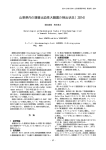
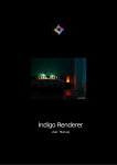
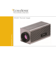
DISCLAIMER -- The following training materials were compiled
from multiple referenced sources and developed into student
products by the Defense Information School for the sole purpose
of supporting its educational curriculum for military public
affairs and visual information professionals. These documents
were provided to the US Navy to support its professional
education, qualification and training program for the Mass
Communication Specialist community. Any further use beyond
the scope outlined here or distribution beyond the Navy public
affairs audience is prohibited.
Table Of Contents
Light Theory.........................................2
Color Theory........................................14
Filters...................................................20
Automated Color Printing....................24
Study Questions................................... 34
Light Theory
Light Theory
Effects of Different Mediums
Transmission
If light passes through a medium it is said to be transmitted. Transparent mediums transmit all
light striking them; you see objects behind them quite clearly. Translucent mediums, such as frosted
glass, transmit only a portion of the light; an object behind them cannot be clearly seen.
Reflection
When light strikes an object and bounces back, it is reflected. There are two types of reflection. Light
that strikes a smooth, polished surface will reflect back at the same angle that it struck the surface. This
is known as specular reflection. Light that strikes a rough surface is reflected back in many directions.
This is called diffused reflection. Diffused reflections form the middle tone areas in a photograph;
specular reflections form the highlighted areas. Reflected light is affected by three factors: the intensity
of the light source, the direction of the light source, and the color of the light source.
Absorption
Light that is neither transmitted nor reflected is said to be absorbed. An object that absorbs the
light falling upon it is called opaque. Absorption (the absence of light) forms the shadow areas in a
photograph. Most objects are opaque. Both opaque and translucent objects have color because they
reflect certain wavelengths of light.
Black objects appear black because they absorb nearly all of the wavelengths of the visible
spectrum.
Reflection
Absorption
Transmission
Light Theory
When speaking of light, black is the absence of all light and white is the presence of all three colors
of light in equal amounts. White items, such as snow, appear white because they reflect nearly all of
the visible spectrum. No object completely absorbs or transmits all light. There is a certain amount of
absorption or reflection in every object. If this were not true, we could not see the object. For example,
the windows in an air-conditioned car appear to be transparent even though they are slightly tinted. The
tint absorbs some of the energy (light) to make the interior of the car cooler. Also, since the surface of the
window is highly polished, some of the light is reflected. So you see, it is the transmission, absorption
and reflection properties of objects that allow us to see objects as well as photograph them.
Bending Of Light
Dispersion
Dispersion is the separation of white light into its individual colors due to the bending of each
different wavelength to a different degree of angle. A prism can be used to separate white light in this
manner. In nature, the water droplets that produce a rainbow also cause dispersion of light. A camera lens
would also disperse light if it were not corrected to prevent dispersion. Dispersion is usually undesirable
for most photographic purposes. Through the years, lens manufacturers have practically eliminated the
occurrence of dispersion. As a result, you do not have to be overly concerned with dispersion.
Refraction
Refraction is the bending of light rays as they enter a medium of a different density. Refraction
occurs when light leaves a medium such as air and enters a medium such as water, glass or even a
vacuum. You probably have witnessed refraction of light in water. A canoe paddle that is partially
immersed appears to be bent at the union between the water and the air. A lens bends light rays in a
controlled manner allowing you to capture the scene in front of the camera, recreating it behind the
lens and recording the image.
Diffraction
When light passes over the edge of an opaque medium it is slightly bent and scattered. This
bending of light rays is called diffraction. When an opaque object is placed so that it partially blocks
the path of the rays from a point source of light, you can see diffraction as a fuzzy edged shadow, (for
example a solar eclipse). The outside edge of the shadow is light and indistinct; it gradually fades into
the deep black of the shadow. Thus, you can see that some of the light is scattered into the shadow
area. In photography, diffraction takes place as light passes over the opaque edge of the diaphragm in
the lens-and-shutter system. Diffraction becomes more and more noticeable as the aperture is closed
farther and farther down.
Light Theory
Exposure
Definition
An exposure describes the amount of light falling on the light sensitive material after the shutter
is released. The exposure is controlled by a combination of aperture and shutter speed. In the
case of digital photography, the light sensitive material is a Charge Coupled Device (CCD).
Exposure Meters
Accurate exposure is fundamental to creating a high-quality photograph. With an exposure meter,
you can venture into a wide variety of lighting conditions and be confident that you will consistently
get good results. You can use an exposure meter to make selective light readings, to handle unusual
and difficult lighting, or to make special creative effects.
Exposure meters, or light meters, are light sensing devices that are good at doing what the human
eye can’t--quantifying light. With an exposure meter you can relate the brightness of light reflected from
a subject toward the camera, or the brightness of the light illuminating the subject, to the sensitivity of
the CCD. The meter expresses this relationship in terms of lens openings and shutter speeds.
Most of today’s 35 mm cameras have exposure meters built into them. In a single-lens-reflex (SLR)
camera, the built-in meter’s photocell measures the intensity of the light passing through the lens. In
a non-SLR camera, the photocell is on the front of the camera body or lens. Some in-camera meters
set exposure controls for you automatically. With the exception of non-SLR auto-focus cameras, most
models have overrides that enable you to change the camera’s aperture and shutter speed. The desire for
added flexibility and control is why some photographers still prefer to use a separate handheld meter.
Whether you use a camera with a built-in meter or a separate handheld meter, the following information
will help you to use your meter to its fullest potential to give you exciting and well-exposed pictures.
Meter-Reading Area
Virtually all in-camera meters are the reflected type--they measure the average brightness of the
light within the lens’ field of view. As you look through the lens of a 35 mm SLR camera, you can see
what the meter sees. Change the lens and you change the area being metered. Most handheld meters
are also reflected-light meters. Many photographers prefer reflected-light meters because they can use
them to take light readings from the camera position. To take a light reading with a handheld reflectedlight exposure meter, you usually stand at the camera position and aim the meter at your subject. To
use an incident-light meter, on the other hand, you usually position the meter as near the subject as
possible, in the same light illuminating the subject, and aim the meter back at the camera (unless the
meter instruction book recommends a different technique).
Light Theory
Types of Exposure Metering with the Nikon D1-H Camera
There are three Exposure Metering modes used to calculate exposure. To select these Exposure
Metering modes, rotate the meter selector while depressing the metering selector lock release (located
on the top right side of the viewfinder). Each mode is indicated in the lower left of the viewfinder.
- Spot Metering calculates the exposure by sampling a very small section in the very center
of the viewfinder. The camera measures light only within the 4 mm circle area. This area is linked to the
current focus area selected by the user unless dynamic AF or a non-CPU lens is used when it defaults
to the center of the frame.
- Center Weighted metering works a lot like Spot metering, but samples a much larger
area in the center of the image. The camera measures light over the entire frame, but assign the greatest
weight to an 8-mm circular area in the center of the viewfinder.
- 3D Color Matrix and Color Matrix metering is the most accurate method of
metering since it samples the entire image to make the correct exposure. The 3D Color Matrix metering uses a 1005 pixel CCD to calculate the best exposure for the frame. The 3D color metering is
only available with G-type and D-type lenses where the range information is used in conjunction with
metered light. Other lenses revert to color matrix metering. This setting is not recommended when
using the exposure lock or the exposure compensation; use center-weighted or spot metering instead.
How Exposure Meters “See”
Both reflected-light and incident-light meters are made to “see” the world as a medium gray. The
assumption is that most subjects, most of the time, are of average tone and reflectance. So long as there
is an even distribution of light and dark subjects in the scene, correct exposure is usually as easy as
pointing the meter or camera at the scene and using the reading you get. But the real world does not
always present subjects to you in such a straightforward way. For example, with either a reflected-light
meter or an incident-light meter, if the main subject is very dark or very light, the indicated exposure
will make the subject appear as a medium tone in the picture. The result will be incorrect exposure
unless you apply your own judgement to the information the meter gives you.
Light Theory
Use a meter reading as a guideline rather than an absolute rule for correct exposure. It is
important that you understand how your camera’s meter works so you can consistently achieve
high quality results no matter what the lighting. The place to begin this understanding is the
instruction manual that came with your meter or camera. The instructions should familiarize you
with the meter’s specific features, its flexibility, and its limitations. Most camera and exposure meter
instructions provide the basic techniques of light measurement and mention some of the situations
that may “fool” the meter. If you can’t find the instructions, write to the manufacturer for them.
Using Reflected-Light Meters
Once you have set the proper ISO on your camera or meter, you are ready to make the exposuremeter reading. With a reflected-light meter (in camera or handheld), point the camera or meter at the
subject. The meter will measure the average brightness of the light reflected from the various parts of the
scene. With an in-camera meter, a needle or diode display in the viewfinder or an LCD display on top of
the camera will tell you when you have achieved the proper combination of lens and shutter-speed settings.
If the camera is fully manual. you must set both the aperture and shutter speed. Automatic cameras may
set both shutter speed and aperture; or they may set just one of the controls, leaving you to set the other.
If you’re using a handheld meter, read the information on your meter and set the camera controls
accordingly. An overall exposure reading taken from the camera position will give good results for
an average scene with an even distribution of light and dark areas. For many subjects, exposuremeter operation is mostly mechanical; all you do is point the meter (or camera) at the scene and set
the aperture and shutter speed as indicated. Your meter does not know if you need a fast shutter speed
to stop action or a small aperture to extend depth of field. You will have to select the appropriate
aperture and shutter combination for the effect you want. There will be situations where either lighting
conditions or reflective properties of the subject will require you to make additional judgements about the
exposure information the meter provides, and you may have to adjust the camera controls accordingly.
A reflected-light meter reading is influenced by the amount of light in the scene and the reflective
properties of the subject. The meter will indicate less exposure for a subject that reflects little light,
even if the subjects are in the same scene and in the same light. Because reflected-light meters are
designed to make all subjects appear average in brightness, equivalent to medium gray, they suggest
camera settings that will overexpose (make too light) very dark subjects and underexpose (make too
dark) very light subjects.
Light Theory
Although reflected-light meters are influenced by the largest areas of the scene, the results will
be acceptable when the main subject fills the picture but is still of average reflectance (neither very
light nor very dark). However, what happens if a relatively small subject is set against a large dark
or light background? The meter will indicate a setting accurate for the large area, not for the smaller,
but important, main subject. Therefore, when the area from which you take a reflected-light reading is
very light or very dark, and you want to expose it properly, you should modify the meter’s exposure
recommendation as follows:
For light subjects, increase exposure by 1/2 to 1 stop from the meter reading.
For dark subjects, decrease exposure by 1/2 to 1 stop from the meter reading.
Selective Meter Readings
To determine the correct exposure for high contrast scenes with large areas that are much darker
or much lighter than the principle subject, take a selective meter reading of only the subject. How do
you do this? Move the meter or camera close to the subject. Exclude unimportant dark or light areas
that will give misleading readings. In making close-up readings, also be careful not to measure your
own shadow or the meter’s shadow.
Selective meter readings are useful for dark subjects against a bright background like snow or
light sand, or for subjects in shade against a bright sunlit background. There is also the reverse of this:
the subject is in bright sun and the background is in deep shade. In all these situations, your camera
has no way of knowing which part of the scene is the most important and requires the most accurate
exposure. You must move in close so the meter will read only the key subject area. For example, if
you photograph a skier posed on a snowy slope on a bright sunny day, taking an average reading of
the overall scene will result in underexposure. The very bright snow will influence the meter and the
reading will be too high. The solution is to take a close-up reading from the skier’s face (or a piece of
medium-toned clothing) and then step back to the desired distance to shoot the picture. Some cameras
with built-in meters have an exposure-hold button or switch, which lock the exposure setting when
you move back. This technique is useful anytime the surroundings are much brighter or darker than
your subjects.
Landscapes and other scenes with large areas of open sky can also fool the meter. The sky is
usually much brighter than other parts of the scene, so an unadjusted meter reading will indicate too
little exposure for the darker parts of the picture. One way to adjust for this bias without having to
move in close is to tilt your lens or meter down to exclude the sky while taking your meter reading.
The sky will probably end up slightly overexposed, but the alternative would be to find a different
shooting position excluding most or all of the sky. There are also graduated neutral density filters that
work well in such situations. A neutral density filter absorbs all colors of visible light evenly, and you
can position a graduated filter so that the darker portion is at the top of the image where it will darken
the sky without affecting the ground below. Incidentally, some built-in meters are bottom-weighted to
automatically compensate for situations like this, so check your manual.
Light Theory
Bright backlighting with the subject in silhouette can also present a challenge. The light shining
directly into the lens or meter can cause too high a reading. If you don’t want to underexpose the subject,
take a close-up reading, being especially careful to shade the lens or meter so that no extraneous light
influences the reading.
Substitute Readings
What if you can’t walk up to your subject to take a meter reading? For example, suppose that
you’re trying to photograph a deer in sunlight. If the background is dark, a meter reading of the
overall scene will give you an incorrect exposure for the deer. Obviously, if you try to take a closeup reading of the deer, you’re going to lose your subject before you ever get the picture. One solution is to take a substitute reading of the palm of your hand, providing that your hand is illuminated
by the same light as your subject. Then use a lens opening 1 stop larger than the meter indicates. For
example, if the reading of your hand is f/16, open up one stop to f/11 to get the correct exposure. The
exposure increase is necessary because the meter overreacts to the brightness of your palm, which is
about twice as bright as an average subject. When you take the reading, be sure that the lighting on
your palm is the same as on the subject. Don’t shade your palm.
Handling High Contrast
How do you determine the correct exposure for a high-contrast scene, one that has both large light
and dark areas? If the highlight of shadow areas are more important, take a close-up reading of the
important area to set the exposure. With color slide film, keep in mind that you will get more acceptable
results if you bias the exposure for the highlights, losing the detail in the shadows. In a slide, lack of
detail in the shadows is not as distracting as overexposed highlights projected as washed-out color and
bright spots on the screen.
But what if the very light and very dark areas are the same size and equally important? One solution
is to take selective meter readings from each of the areas and use a f-number that is midway between
the two indicated readings. For instance, if your meter indicates an exposure of 1/125 second at f/22 for
the brightest area and 1/125 second at f/2.8 for the darkest area--a range of six stops--set your camera
1/125 second f/8. This is a compromise, but sometimes it is your only choice short of coming back
another day or changing your viewpoint, and the composition of the picture, to eliminate the contrast
problem.
Using Spot Meters
Perhaps the best solution for a selective meter reading is offered by the spot meter. Handheld
averaging meters generally cover about 30º, while handheld spot meters typically read a 1º angle. The
angle of spot meters built into the camera are usually wider, about 3º-12º. The advantage of a spot
meter is that is allows you to measure the brightness of small areas in a scene from the camera position
without moving to take a close-up reading. Since a spot meter measures only the specific area you point
to, the reading is not influenced by large light or dark surroundings. This makes a spot meter especially
useful when the principal subject is a relatively small part of the overall scene and the background is
either much lighter or darker than the subject. Spot meters are also helpful for determining the scene’s
brightness range.
Light Theory
A spot meter can take more time to use since it usually requires more than one reading of the scene.
This is particularly true when the scene includes many different bright or dark areas. To determine the
best exposure in such a situation, use the same technique described previously for high-contrast subjects.
Select the exposure halfway between the reading for the lightest important area in the scene and for the
darkest important area in the scene. You can sometimes create more dramatic pictures by intentionally
exposing for one small area, such as a bright spot of sunlight on a mountain peak, and letting the
dark areas fall into black shadow without detail. Spot meters are ideal for such creative applications.
Using Incident Meters
To use an incident-light meter, place the light meter near the subject and aim the meter’s lightsensitive cell back toward the camera. The meter reads the amount of light illuminating the subject, not
light reflected from the subject. The meter ignores the subject and background characteristics. As with
a reflected reading, an incident reading provides exposure information for rendering average subjects
correctly, making incident readings most accurate when the subject is not extremely bright or dark.
When taking an incident-light reading, be sure you measure the light illuminating the side of the
subject you want to photograph, and be careful that your shadow does not cover the meter. If the meter
isn’t actually with the subject, you can get a workable reading by holding the meter in the same kind
of light the subject is in. Because the meter is aimed toward the camera and away from the background
light, an incident reading is helpful with backlighted subjects. This is also the case when the main subject
is small and surrounded by a dominant background that is either much lighter or darker.
The exposure determined by an incident-light meter should be the same as reading a gray card
with a reflected-light meter. Fortunately, many scenes have average reflective properties with an even
mix of light and dark areas, so the exposure indicated is useful for many situations. However, if the
main subject is very light or very dark, and you want to record detail in this area, you must modify the
meter’s exposure recommendations as follows:
For light subjects, decrease exposure by 1/2 to 1 stop from the meter reading.
For dark subjects, increase exposure by 1/2 to 1 stop from the meter reading.
You will notice that these adjustments are just the opposite of those required for a reflected-light
meter. An incident meter does not work well when photographing light sources because it cannot meter
light directly. In such situations you will be better off using a reflected-light meter or an exposure
table.
If the scene is unevenly illuminated and you want the best overall exposure, take incident-light
readings in the brightest and darkest areas that are important to your picture. Aim the meter in the
direction of the camera position for each reading. Set the exposure by splitting the difference between
the two extremes.
10
Light Theory
How to Check Your Exposure Meter and Camera
If your results are consistently too light or too dark, your meter may be providing erroneous
readings because of age, extensive use, or malfunction. The first thing to suspect, when a meter fails or
readings become erratic, is the battery. Handheld and in-camera meters require fresh batteries to provide
accurate readings. You should replace batteries at least once a year. Cold weather is particularly hard
on batteries, so if you’re shooting in the winter, carry backup batteries in a warm inside pocket where
they’ll retain their charge. If new batteries don’t cure the problem, have your camera or meter checked
by a professional repair technician or by the manufacturer.
Simple Meter Check
To check the accuracy of your meter, you can compare its readings with a guide such as the daylight
exposure table found on page 13. On a sunny day, aim your camera meter at a frontlighted, average
subject. The exposure indicated by the meter should match the recommendation in your guide within a
1/2 stop. If your meter indicates a different setting, it may need repair or an adjustment. If your meter
indicates the correct exposure but your pictures are still too light or too dark, then your camera’s shutter
or lens aperture may be at fault.
This simple daylight exposure guideline works because it is based on the relatively constant light
from the sun plus the sky on sunny days. Sometimes called the “f/16” rule, the exposure for a frontlighted,
average subject in bright sun and distinct shadows is f/16 with a shutter speed that matches the ISO.
For example, in conditions where you are using film, say KODAK GOLD 200 Film (ISO 200), the
exposure should be 1/250 second at f/16, the same as the film carton recommendation. Incidentally,
even though most cameras do not have a 1/200 second shutter speed setting, the exposure latitude of
the film will easily cover the slight underexposure at 1/250.
As with a meter reading, the exposure is adjusted for changes in the lighting level, the direction of
the light, reflectivity of the light, and the reflectivity of the subject. For example, you should decrease
exposure by one stop for bright sun on light snow or sand, and increase exposure by one stop for an
average subject in weak or hazy sun (soft shadows). There is an additional stop increase for cloudy bright
conditions (no shadows), and another for heavy overcast or open shade. Using the previous guidlines,
the change from bright sun to heavy overcast or open shade for an average subject is three stops --a
suggested exposure for f/5.6 at 1/250. Increase exposure by one stop (either a slower shutter step or
larger lens opening) from the initial exposure setting for sidelighting, and two stops for backlighting.
Digital Cameras and ISO
Digital cameras have an ISO rating indicating their level of sensitivity to light. ISO 100 is the
“normal” setting for most cameras, although some go as low as ISO 50. The levels of sensitivity can
be increased to 200, 400, 800, or even 3,200 on high-end digital SLRs. When increasing the sensitivity,
output of the sensor is amplified, so less light is needed. Unfortunately this also amplifies undesired
noise, which creates grainy pictures, just like in conventional photography, but for different reasons.
11
Light Theory
It is similar to turning up the volume of a radio with poor reception. Doing so will not amplify
the (desired) music but also the (undesired) hiss and crackle or “noise”. Improvements in sensor
technology are steadily reducing noise levels at higher ISOs, especially on higher-end cameras. Unlike
conventional, digital cameras allow you to instantly and conveniently change the sensitivity level.
200 ISO
800 ISO
Bracketing
When you are faced with a scene that challenges normal metering techniques, a good solution is
to bracket your exposures.
Bracketing doesn’t simply mean guessing. It is a calculated technique to obtain a few additional
insurance exposures based on your best estimate for correct results. The key is to recognize those unusual
situations or unorthodox lighting conditions where a single exposure may not assure you of success.
Bracketing is a simple procedure. First take a reflected-light meter reading of the subject from the
camera position or use the recommendation in an exposure table. This step will give you an approximate
exposure and provide a starting point for making any subsequent adjustments. Next, take one picture
using this exposure. Then bracket your exposure by using one stop larger then one stop smaller than
the indicated exposure. For extra assurance, you can use a bracketing range of ± 2 stops.
Daylight Conditions
Primary considerations for exposure calculation with daylight are intensity, direction, and the
color quality of daylight.
Intensity. From early morning until late evening, even on a clear day, the intensity of daylight is
constantly changing as the sun rises, moves across the sky, and sets. Although the intensity of daylight
varies throughout the day, the time between about two hours after sunrise and two hours before sunset
is when the light intensity in a specific location remains constant for exposure purposes. Colors in
your photographs will vary depending on the time of day that you made them. Photographing early or
late in the day can produce strikingly beautiful pictures simply because the light is not its usual “white”
color. The Direction of light is important when calculating proper exposure. Use the chart on page 13
to decide proper camera adjustments for various lighting conditions.
12
Light Theory
Conditions for daylight exposure can be divided into six intensity conditions:
1. Bright or Hazy Sun on Light Sand or Snow - The amount of reflected light from sand or snow, the
intensity of light in such a scene, is greater than a scene with average reflectance. It requires a decrease
in f/stop or a faster shutter speed.
2. Bright or Hazy Sun (distinct shadows) - Daylight exposure recommendations for a specific film
(CCD), are based on the exposure required for an average scene in bright or hazy conditions. This
exposure is termed the basic exposure.
3. Weak, Hazy Sun (soft shadows) - This condition is from a heavier or thicker haze or cloud cover.
This causes a decrease in daylight intensity. To compensate for this decreased daylight intensity, a
larger f/stop or slower shutter speed is required to double the basic exposure.
4. Cloudy, Bright (no shadows) - This occurs when there is an overcast and the sun is diffused
causing no shadows to appear around your subject.
5. Heavy Overcast (no shadows) - This occurs when there is thunderstorm conditions. Sun is
diffused.
6. Open Shade - Shooting outdoors where the subject is completely in the shade.
Bright or Hazy
Sun or Light
Sand or Snow
f/22
Bright or Hazy
Sun (Distinct
Shadows)
f/16
Weak, Hazy
Sun (Soft
Shadows)
f/11
Cloudy Bright
(No Shadows)
f/8
Heavy
Overcast
f/5.6
Open Shade
f/5.6
Exposure Compensation
The relationship between the sun and your subject will determine whether or not compensation is
necessary with your exposure.
No Change
Open up 1 stop
Open up 2 stops
13
Color Theory
G
Y
C
R
B
M
14
Color Theory
Color Theory
Color Star
On the previous page is a picture of the color star. The color star is the foundation of color theory.
The design of the star is very simple. The primary colors are R (red), G (green), and B (blue). The
secondary colors are cyan (C), yellow (Y), and magenta (M). Combining the two colors on either side
of the color that is to be produced can produce any color on the color star. Example: Y + C = G, or G
+ B = C. If a green filter and a cyan filter are placed in front of a white light the resulting light will
be blue. The colors that are opposite of each other on the star are called complements (opposites). Y
and B are complements, C and R are complements, and G and M are complements. When magenta is
added to a print, at the same time and same amount, green is being subtracted. Complementary colors
are directly related to each other.
Kelvin Temperature
The color spectral quality of the light used to illuminate a subject plays a significant part in
color photography. Color temperature is a useful means of identifying the spectral quality of certain
types of light sources. Since use of color temperature to describe a light source can be misleading
let’s examine this subject more thoroughly.
Experiments by Lord Kelvin developed the color temperature system that bears his name. These
experiments involved observing color changes in a “black body” while it was being heated to a high
temperature. A “black body” is a perfect temperature radiator. It absorbs all of the heat incident upon
it and reradiates it immediately.
When the black body was heated and a color change occurred, the temperature was noted and
thereafter used to identify that particular color. Lord Kelvin used “absolute” temperatures - also called
Kelvin temperatures - in his measurements. Kelvin temperature is written as K and is the centigrade
temperature of the black body plus 273 degrees. Lord Kelvin used his process to establish values for
the special characteristics of light. Artificial light sources, however, can provide useful supplementary
lighting to daylight as fill-in for shadows (to make them lighter) and take the place of daylight entirely
for photography of small areas and close-ups. The term daylight includes direct sunlight, skylight, and
reflected light. Daylight is all forms of light, direct or indirect, that originate from the sun. Of importance
to the photographer are the effects of the atmosphere on sunlight and the amount of atmosphere through
which sunlight passes.
15
Color Theory
The shorter wavelengths of light (violet and blue) are scattered by the atmosphere much more than
the longer wavelengths (reds). The color composition of sunlight becomes increasingly deficient in
blue as the atmosphere becomes thicker because the light has to travel through more atmosphere (early
morning and late afternoon). As the sunlight becomes more deficient in blue, it appears more yellow.
The amount of scattering also depends on the condition of the atmosphere. When the atmosphere
is clean (has little moisture or fine dust in it), there is less scattering than when the atmosphere is hazy
or dirty (having a good deal of moisture, fine dust particles, or smoke). The variation in daylight can be
expressed as color temperature. Sunlight coming from overhead on a clear day has a color temperature
of about 5400 K. Just after sunrise and just before sunset, the color temperature ranges between 2000
K and 4000 K. Not only is the color of daylight different early in the morning and late in the afternoon,
but the intensity is also less. These are important considerations when taking pictures at these times
of the day.
Skylight
Skylight is different from direct sunlight because it is caused chiefly by the scattering of the shorter
wavelengths. It is light that has been scattered by the atmosphere. Skylight appears bluer than direct
sunlight. Skylight on a clear day may register anywhere from 6,000 K to 18,000 K.
It must be noted, however, that color temperature refers only to the visual appearance of the
light source and not to it’s photographic characteristics. For example, fluorescent and tungsten lamps
may present a visual match but the photographic results differ appreciably. Some fluorescent lamps
manufactured now are equal in color quality to daylight. However, most fluorescent lamps emit a
predominant greenish cast which usually can be corrected by a .30 magenta filter when using daylight
color film. Color temperature is most reliable when used to describe the spectral quality of tungsten
light sources as opposed to fluorescent.
The spectral quality of a light source is related to its Kelvin temperature. Incandescent lamps
produce light when electrical current is passed through a thin filament causing the filament to glow.
The hotter the filament becomes the brighter the light. With the increase in temperature, there is an
accompanying change of color quality. At lower incandescent temperature, the filament will glow red,
and as the temperature rises, the color changes to blue and finally to white. Thus, you can see color is
related to temperature. The most commonly used light sources are daylight, tungsten and flourescent
light; each has it’s own Kelvin temperature. To the eye, most of these light sources appear the same;
but they will not photograph the same with CCD’s.
Daylight
Daylight is the light with which photographers are most familiar. It is the light that we use the
most. Naturally, daylight is the only practical light source for general outdoor photography. The Kelvin
Temperature for daylight is 5400 to 5500 K.
16
Color Theory
Tungsten Light
Tungsten light is high in red color (wavelength). An example of a tungsten bulb is your
standard house hold bulb. If daylight film is used under a tungsten bulb without a filter or a flash your
photos will be high in red color. An example of this is the Photography text book by Barbara London
and John Upton. Tungsten’s Kelvin temperature ranges from 3200 K to 3400 K degrees. This is a
huge difference from the Kelvin temperature of daylight, which is 5400 K to 5500 K degrees. The
photographer must make on of the following adjustments when shooting under this type of light: shoot
with tungsten balanced film, use a conversion filter (which is covered later).
Flourescent Light
Fluorescent light is high in bluish-green color. An example of the type of fluorescent bulb we
are talking about is the over head lights in the DINFOS building. These fluorescent bulb temperatures
range form 3500 K to 4500 K degrees Kelvin. The problem with florescent light is there is no fluorescent
balanced film. If shooting under florescent light with daylight film the prints will have a greenish, bluish
tint. When shooting under this condition the photographer must make the following adjustment: either
shoot with a flash, or use a filter (this is covered later in this student guide).
Filters
Whenever possible, the source of illumination and the color emulsion should be matched (or
balanced). For example - when shooting indoors under tungsten light source the film should be tungsten
film.
Color Compensating Filters
Color-compensating (CC) filters come in hues of blue, green, red, magenta, yellow, and cyan.
Because there is a very large selection of densities available (from 0.025 through 0.50), these filters
can be used to make either very subtle or very large tonal changes . CC filters are often used in slide
duplicating, printing, and picture taking.
Color Compensation With Digital Cameras
The perceived color of a light source varies with the viewer and other conditions. Color temperature
is an objective measure of the color of a light source, defined with reference to the temperature to which
an object would have to be heated to radiate light in the same wavelengths. While light sources with a
color temperature in the neighborhood of 5,000–5,500°K appear to be white, light sources with a lower
color temperature, such as incandescent light bulbs, appear to be slightly yellow or red. Light sources
with a higher color temperature seem to be tinged with blue.
Digital imaging reproduces all the colors in the color spectrum by using the three primary colors.
These colors are captured, stored, and displayed as pixels. Each pixel represents a specific brightness
of red, green, and blue light. 17
Color Theory
Although the color of light reflected by an object varies with the color of the lightsource, the
human brain is able to adapt to changes in lighting, ensuring that we see white objects as white under
most lighting conditions. A digital camera is able to mimic this adjustment so colors that appear white
to the human eye also appear white in your photographs. This adjustment is known as “white balance.”
Remember, a change in lighting will have an effect on the outcome of your image if
you do not change your white balance setting. Most digital cameras will adjust for daylight,
tungsten, flourescent, cloudy, or flash - so colors are rendered normally. Most digital cameras
will have a white balance setting that can be adjusted for different lighting situations. It
is very important to become aquainted with the menu setting of your camera prior to use.
White-balance measurements are performed using a through-the-lens metering system. Even
if the subject and camera are under different lighting, the camera will be able to adjust white balance
to suit the subject when auto or preset white balance is used.
NOTE: Directions on the adjustment for your camera’s white balance can be found in
the user’s manual.
18
Filters
Information
Filters
Filters are primarily of two types, dyed gelatin and colored glass. In this section, the advantages
and care for both will be discussed.
Gelatin Filters
The simplest filter is a sheet of dyed gelatin that may be cut into an appropriate size piece and
held in front of the lens with a suitable holder. Gelatin filters are supplied in the widest variety of
colors. Thus, they are very popular for experimentation, color photography, and for use with odd-size
lenses. The main disadvantage of a gelatin filter is that it is delicate. Scratches, discolored spots, and
fingerprints will render the filter useless.
Glass Filters
Glass filters are made out of dyed glass or by using a sheet of dyed gelatin between two sheets of
glass. They come in a variety of sizes (designated in millimeters or series) and types. A glass filter may
be either screwed into the front of the lens or held by a retaining ring (used for series filters). Glass filters
are more expensive and durable than gelatin filters, but do not come in the variety of colors and density
ranges. Each glass filter should be treated as if it were a lens. Any lint or dust should be removed with
a lens brush. Lens tissue moistened in lens cleaner should be used to remove fingerprints. All filters,
regardless of the method of manufacture, fade with use. It is, therefore, a good idea to replace your
filters at regular intervals.
Using Filters with a Digital Camera
A digital camera removes the necessity of manual exposure compensation when using filters. The
camera will automatically adjust for whatever exposure is necessary.
19
Filters
Filter Factor
Filter factors serve only as guides. The factors vary from manufacturer, even with filters that
appear to be the same color. Since overexposure can eliminate the effect of a filter, it is a good idea to
“bracket” your exposures by full stops to make sure you achieve satisfactory results.
Compensation Method #1
The ISO Method
One way to use this factor is to divide the factor into the ISO or exposure index you are using
and then set your meter to this new figure. For example, at ISO 400 and a light-green filter having a
factor of 4, divide the filter factor into the film speed to calculate the new ISO, which is 100 (400 ÷ 4
= 100). Once you have set the meter at the new ISO, you can use the meter in the normal way. Always
remember to reset the ISO meter to the original ISO setting when you are not using the filter. Use this
method only with hand-held light meters and don’t reset meters that are built into the camera.
Compensation Method #2
The F/Stop Method
Another method of applying the filter factor is through the f/stop setting. Before applying this
method, you must be thoroughly familiar with f/stops and their function in changing exposure.
For example, a filter factor of 2 requires a one stop increase (doubling of exposure) from the basic
setting. This means that if your exposure is f/8 at 1/125 and you decide to use a yellow filter with a
factor of 2 your new exposure is f/5.6 at 1/125.
Compensation Method #3
The Shutter Speed Method
A third method to compensate for the filter factor is to multiply the exposure time by the filter factor.
For example, a basic exposure without a filter is 1/500 at f/8. After inserting a filter with a factor of 4,
the new exposure would be calculated as 1/500 X 4/1 = 1/125. The f/stop would remain the same.
Because most modern SLR cameras come with a through-the-lens (TTL) metering system it is not
necessary to use the previously mentioned filter factor methods. Simply place the filter on your lens
and meter the scene for the correct exposure!
Filters for use with digital cameras include neutral density, polarizing, and some special effects
filters. Camera settings and software for digital manipulation has reduced the need for contrast and
color compensating filters for use with the digital format.
20
Filters
Types of Filters Used with Digital Photography
Ultraviolet (UV)
Filters out bluish ultraviolet, removes blue from shadows, and reduces haze. Many photographers
use the UV filter as a permanent attachment to their lenses to protect the lens from damage.
Neutral Density
This filter absorbs equal amounts of light from all parts of the spectrum. These filters will leave the
color balance unchanged. The purpose is to increase the exposure needed for a scene so the photographer
can use a slower shutter speed to blur motion or a larger aperture to decrease depth of field.
Polarizing
Affects light vibrating only at certain angles. Primarily used to remove reflections from glass
and water, this filter can also be used to darken skies and intensify colors.
Sometimes situations occur that make it necessary to use color emulsions and light sources that
do not match. Acceptable results are obtainable if filters are used to alter the color quality of the light
entering the lens. This can be accomplished by removing the extraneous wavelengths of light. The
three common categories of filters include Conversion, Light Balanceing (Correction) and Color
Compensating (CC)
Conversion
Conversion filters are dense (in color) and are used for major changes in Kelvin temperature.
Examples when you would use conversion filters include tungsten color film under daylight illumination
(85 series, amber), daylight color film under tungsten illumination (80 series, blue), daylight color film
under fluorescent light (FLD), or tungsten color film under fluorescent light.
Conversion filter charts are just guides. For the best results follow the recommendations of the
film manufacturer. These recommendations apply primarily to color reversal rather than color negative
film. A camera with through-the-lens metering (such as a most Nikon digital cameras), automatically
adjusts for filters and the resulting exposure changes.
21
Filters
Light Balancing Filters
Light-balancing filters are paler than conversion filters. They are used for slight adjustment within
the general light balance of the film (e.g., matching daylight film to various types of daylight lighting,
etc.). Light balancing filters make slight adjustments in the Kelvin temperature. There are two series of
filters .81 (yellow) and .82 (blue). Add a .81 filter to warm an image and add a .82 to cool an image.
Color Compensating Filters
Color-compensating (CC) filters come in hues of blue, green, red, magenta, yellow, and cyan.
Because there is a very large selection of densities available (from 0.025 through 0.50), these filters
can be used to make either very subtle or very large tonal changes . CC filters are often used in slide
duplicating, printing, and picture taking.
22
Automated Color Printing
Automated Color Printing
Minilabs
The automatic print-processors are known as minilabs. A minilab is a self-contained lab. The
operator can use one machine to process negatives and another machine to print the negatives when
not using a digital camera. In this section we will discuss a couple different types of printers. The
new minilabs can now print digital photos using the wet process and achieve the highest quality image
available. The printers are designed to work hard and make the calculations so the operator does not
have to, however the machines are not perfect. Sometimes the operator needs to make some adjustments
the machines were unable to make.
The photographic printer is very much like a camera. Rather than using film, the printer uses color
photographic paper. Whereas the subject of the camera may be the beautiful sunset, or cousin Bob
at his wedding; the subject of the printer is the image to be printed. The light source for the camera
is the sun or a flash; the printer has a lamp house. The camera has a built-in light meter to determine
exposure; the printer has three photocells to determine the exposure for the three primary colors of light:
red, green, blue. We set the camera for the desired ISO; likewise, we balance the printer for speed of
the paper we’re using. The printers use either the white light printing method, or a film scanner wired
into a laser head. The machines contain six tanks of chemistry for the RA-4 chemical process. Here
at DINFOS we have several different models of printers. All printers can be programmed to print
different sizes of prints. Most machines can print from widths starting at 3.5” up to 12”. The largest
we are able to print is 12” X 36”.
If the proper maintenance is performed on a daily, weekly, and monthly basis, then the processor will
perform up to expectations for many years. The machines must be maintained and cleaned if they are
to remain operational.
Automated Printing
Printing with the automated printers removes the guess work and is a great time saver compared
to the old ways of custom color printing. All automated printers will consist of the follow steps: start
up, quality control, machine setup, place negative, make color adjustments, print, and shut down (at
the end of the day).
23
Automated Color Printing
Startup
Different printers have different start up procedures. All printers come equipped with a program
timer. The program timer is a timer that is programmed by the operator to turn on the heaters to
the machine before the operator comes to work. This will warm the chemistry to a temperature that
will provide optimum results and allows the machine to ready itself for daily startup procedures. The
standard for the program timer is approximately one hour before arrival time. This is adjusted for the
time of year and the location in the world. For example, in the winter time the operator may want the
timer to come on earlier in the morning, or in the summer, to come on a little later. Again, this is all
at the discretion of the operator.
The operator should check the crossovers for crystallization. Crystallization occurs when the
water has evaporated and what is left behind are crystals left from the chemistry. If the crossovers and
gears are free of crystallization, turn the machine on. If the crossovers are not clean, then spray them
off with water and start the machine. It will take the machines about 15 minutes to be totally ready to
go after the machine is turned on.
Next, make sure the proper channel has been selected. The channel button controls the size of the
print. For example, if the desired size of print is 5”X7”, make sure the proper channel is set for 5X7
not 8” X 10”. The size of the print is selected on the computer monitor of the printer.
There are some more overall general setups that must be checked on some of the machines. One
of them is to ensure the output of the machine is to make a print. Some machines can be set up to out
put to a CD, Zip, the Intranet, 3 1/2” disk, or to print from a flash card. Another item to check is that
the proper magazine paper size is on the machine. As discussed earlier, the machines will print on different sizes of paper, however the machine will not print a 5” X 7” on a 12” wide paper. The machine
must have 5” or 7” wide paper available. Remember, the input media, i.e. compact flash card, must be
selected. These machines will accept several different types of media, so make sure the proper media
is selected.
Printing
To make a test print on the automated machines, make a selection of N (normal) for C (cyan),
M (magenta), Y (yellow), and D (density). If printing a large amount of prints or a few large prints,
it is always a good idea to print a test print to make sure the monitor and the printer are calibrated
together. On the automated machines, the operator is able to use all three filters. The machine will
make the adjustment to eliminate neutral density. The standard setting is 5CC. This means that if
the operator pushes the -1Y key, he/she subtracted 5CC yellow from the print. Example: if the test
print is too yellow, subtract yellow. If a test print is too green, add magenta. If a test print comes out
of the printer and looks good when viewed through a 10 blue viewing filter, then the print is too yellow. Again, you need to half the viewing filter to 5 and subtract 5CC from the machine (which is -1
Y), and the print should be correct. Density corrections are made by selecting a density button other
than the “normal” button when making the exposure. Each succeeding number (+ or -) will change
the density in the print by approximately 20 percent.
24
Automated Color Printing
Shutdown
Unless working in a 24-hr lab, where the machines are shut down on a cleaning schedule only,
all machines will be shut down at the end of the workday. The shut down procedures are different on
the different machines. The basic process is to turn off the machine, either by a switch or by shutting
the computer software down. Once the machines are shut down, the crossovers need to be rinsed
off. This will prevent crystallization from building up on the crossovers and the rollers. Some of the
machines will require the lids to be left propped open and some do not. Propping the lids open stops
condensation build up.
All equipment in the DINFOS training environment is maintained by professionally trained
DINFOS staff. Do not attempt maintenance procedures of any kind without proper authority!
Quality Control
Quality control is the process of making sure the chemistry and the machine is ready to perform
to required standards. In other words, the main goal of quality control is to achieve repeatable results.
If you achieve desired results when printing on a machine one day, then the operator should be able to
achieve the exact same results when printing on the same machine on a different day. Quality control
will be covered in-depth during the Demo. The main point here is that the machine must be monitored
on a daily basis to ensure that it is working within its control limits.
25
Automated Color Printing
Noritsu
QSS-2901
The QSS-2901 (2901) combines a high performance minilab and advanced digital workstation
into a versatile and easy-to-use system that generates high quality prints on silver halide paper from
virtually any image source to include flash cards. The high speed precision scanner also reads and
automatically corrects images from the most popular film types. A full range of negative masks and
attachments are available for the most popular film sizes, 135mm, 240mm, and 120mm.
Engineered for high performance, the 2901 on fully automatic printing produces up to 1,250 5”
X 3.5” prints per hour. The 2901 allows for enlargements up to 12” X 18”, print-to-print reproduction,
and specialty prints ranging from greeting cards, photo business cards, to index prints.
At the heart of the 2901 is a new print engine called the Micro Light Valve Array (MLVA).
MLVA is a highly efficient and cost effective technology that lets you create 400 dpi resolution digital
prints on silver halide paper, saving time and material costs. Designed for rugged reliability, the MLVA
features a mechanism that ensure consistently vivid reproductions over its life cycle and maintenance
costs that are a fraction of traditional digital and negative printing systems.
Scanned images are displayed in 4, 6, 28, or 40 frame modes on the 17” monitor. As the images
appear on the monitor, ranges of graphic icons with simple point-and-click commands are displayed
to simplify operations and reduce operator errors. With the images being scanned and displayed on
the monitor and corrections being made on the monitor the correction time is reduced far below that of
custom color printing. The 2901 is a self-contained machine with built in replenisher and waste tanks.
The 2901 uses RA-4 chemistry.
26
Automated Color Printing
The following is a list of the different print modes:
1. Pre-judge printing (PJP) - The scanners correction results can be corrected on the display
monitor. PJP eliminates the need for a test print. It is recommended that a test print be made
before a number of prints are printed from a frame. This will ensure that the monitor and
the printer are totally calibrated and a lot of paper and chemistry will not be wasted. The
number of prints must be specified for each frame.
2. Auto print (Auto) - The negatives are placed into the auto mask and are automatically
fed into the scanner. After the scanner has made corrections, prints are made automatically
without displaying the scanner’s correction results on the display monitor.
The standard printing mode here at DINFOS is PJP and 6-frame viewing. This mode is
on the upper right-hand side of the monitor. If PJP 6 frame is not there, use the mouse to press
the viewing option and select “PJP”.
After the 2901 is set on PJP and six frame viewing, we have to select the “output desired.” The
choices are prints, index, digital, or any combination of these three choices. We are going to select
prints at a size of 3” X 5”. Insert the input media desired. In this case the input will be a compact
flash card. The operator can now decide if the desired corrections are correct. If all displayed frames
are good, press the “start” key. This will begin the print process. The screen will now display the next
set of frames. If a frame is not corrected to the operator’s liking, simply select the frame in question
and make the desired changes. The operator has the options of changing the number of frames needed
or changing the color balance and density. The instructor will demonstrate the exact operations of the
keyboard.
The 2901 has several different operator maintenance tasks that might have to be performed while
operating the machine. Your instructor will monitor you if you have to perform any of these tasks. The
following is a list of operator tasks that will need to be performed at some point.
1. Paper magazine loading - If the paper magazine runs out of paper while you are using
it, the machine will tell you on the display monitor that you are out of paper. Loading the
paper is an operator maintenance task. The main things to remember when loading the
magazine is to make sure the paper emulsion is loaded up and be careful not to expose the
paper to any light.
2. Adding replenished - The machine will use up chemistry while it is being used.The machine
will stop printing if it runs out of replenishing chemistry. Again, the monitor will instruct the
operator to add replenishment. This is a very simple task to perform. Your instructor will
monitor you while you perform this task. It is critical to mix chemistry in the correct
order and at the correct temperature. Careful attention must be taken not to add the chemistry
to the wrong replenishing tank or to contaminate one chemistry with another.
27
Automated Color Printing
3. Empty waste tanks - The machine will produce waste chemistry while it is being used.
This waste solution must be emptied. The machine will inform the operator on the
monitor that the waste tanks need to be emptied. If this happens, simply empty the waste
tanks into a bucket used for waste solutions. These solutions contain silver so they must
be recycled. Your instructor will monitor you performing this task.
Shutdown
When printing is complete for the day, the machine must shutdown. As with start up, there
is a proper procedure for shutting the machine down. The life of the 2901 will be extended if the
proper start up and shutdown procedures are followed. After making sure all prints have come out of
the machine, use the mouse to press the “F” key on the screen. Push the “down key”, then press the
“yes” key on “close down checks”.
1. Display totals? Select the “yes” or “no” key depending if you want to see the daily totals.
2. Save Data? Press the “yes” key, insert a floppy disk into the machine and press the “yes”
key. The data is now backed up to a floppy disk. If the data does not need to be backed up
to a floppy, then press the “no/stop” key.
3. Clean the 135/240 Auto Film Cleaner (AFC) and dummy heads. Set the cleaning leader
into the 135/240 AFC; Follow the display instructions. After cleaning the 240 lane, wipe
the stains off of the dummy head with a firmly squeezed damp cloth.
4. Set the program timer? If the program timer needs to be set for a different time then
press the “yes” key. If it does not, press the “no/stop” key. If the “yes” key is pressed, the
machine will guide the operator through step by step.
5. Carry out automatic cleaning? Press the “yes” key. The machine will automatically clean
the upper guides and refill the processing tanks with water.
6. Check the refilling water tank? Make sure the refill tank is full with water.
7. Wash the squeegee racks - Rinse the squeegee racks off.
8. Wash the processing racks? Wash the processing racks. Use a water bottle to remove all
the crystallization from the racks, rollers, gears, and the sides of the processing tanks.
9. Prop open processor upper cover - the processor’s upper cover needs to be propped
open over night to prevent condensation from forming inside the machine.
When finished, the 2901 will now go into the Program Timer mode.
28
Automated Color Printing
Monitor
Film Scanner
Circuit
Breaker
Waste
Tanks
CPU
Replenishing Tanks
Both the QSS-2901 and the QSS-3213 have processing tanks. The tanks and chemicals
contained are as follows:
From left to right:
- 1 Developer Tank
- 1 Beach/Fixer Tank
- 4 Stabalizer Tanks
- 6 Tanks total
29
Automated Color Printing
Noritsu
QSS-3213
The QSS-3213 (3213) is a high speed and high capacity print processor digital minilab. This
minilab provides high speed scanning of both film and digital media. Sharp photos are produced, and
both speed and quality are assured. The QSS-3213 has a high specification computer which enhances
the image processing ability and enables an even wider range of digital media to be supported. In
addition to the conventional maximum print size of 12”x18”, you can now make prints that are twice
as long (12”X36”). The jumbo panorama prints can be used for group photos and panorama photos.
This machine is equipped with a newly developed “multi-paper-matching” laser system that
enables a resolution of 300dpi, this minilab will make high quality prints. Prints from digital cameras as
well as other kinds of prints are made with delicate color gradations to produce sharp and vivid prints.
The QSS-3213 offers a program called DIGITAL ICE; this automatically corrects
dust and scratches prior to printing from film, turning ruined images into blemish free prints.
Like the QSS-2901, the QSS-3213 has easy to operate procedures. Simply clicking the
appropriate icon on the main menu screen enables the user to provide the selected digital service.
The 3213 accepts many forms of input media, just as the 2901 does. Media accepted includes
compact flash, film, (conventional and Advantix, both black and white and color), slide film, photographs
and any printed matter, CD, Zip, memory stick, SmartMedia, and SD card. The input media the services
provided from the QSS-3213 are just as varied as the input media. The print and digital services offered
are enlargements, digital camera prints, prints from slide film, prints from application software (MS
Word, PowerPoint, etc...), CD-R writing services, writing images from film, from media, and from prints.
30
Automated Color Printing
Printing
Assuming there are no problems with the start up procedures, the operator will need to ensure
that the proper negative mask is in place. If there is a problem with the start up procedures notify your
NCOIC . Once the proper negative mask is in place select the proper print channel and proper printmode. This is done just like the QSS-2901. Essentially, they both operate in similar fashion.
IMPORTANT!!!
The film scanner on the QSS-3213 is not permanently attached to the control
stand. DO NOT LEAN ON THIS STAND!!
When the printing is completed for the day, the machine must be shut down. As with start
up there is a proper procedure for shut down. The life of the QSS-3213 will be extended if the proper
start up and shut down procedures are followed. To shut down the machine press the F key and select
Menu, then press the yes/start key.
1. Display totals? Select the “yes” or “no” key depending if you want to see the daily totals.
2. Save Data? Press the “yes” key, insert a floppy disk into the machine and press the “yes”
key. The data is now backed up to a floppy disk. If the data does not need to be backed up
to a floppy, then press the “no/stop” key.
3. Clean the AFC. Follow the display instructions.
4. Check whether or not to change the program timer.
5. Schedule the disk defragmentation.
6. Carry out the automatic cleaning.
7. Empty the waste tanks.
8. Check the refilling water tank level.
9. Remove the upper guides and squeegee unit and clean them.
10. Keep the processor top cover slightly open.
11. Clean the AFC. Follow the instructions on the monitor.
12. Clean the optical parts of the scanner section. Follow instructions.
31
Study Questions
Captions
Study Questions
1. Which part of a caption is the most important?
2. What are the four elements of a caption?
3. The verb in the first sentence of the caption should be in the ____________ tense.
4. The best way to identify people in a caption is ____________.
5. “U.S. Marine Corps photo by LCpl. John Doe” is an example of a __________________.
Light Theory
1. Name the all-inclusive term for wavelengths that can be seen with the human eye.
2. Name the process that occurs when light strikes and then bounces off an object.
3. Name the type of medium through which an object can be clearly seen.
4. What is the term used to describe why light rays bend in water?
5. Name three properties of light that allow us to see and photograph objects.
6. What two factors give the speed of radiant energy?
32
Study Questions
Color Theory
1. Draw the color star and list the primary and secondary colors.
2. As the Kelvin temperature rises, the color___________increases.
3. What is the Kelvin temperature of daylight?
4. With digital cameras, what menu will you use to adjust for a change in lighting situations?
5. How are colors captured, stored, and displayed with digital cameras?
Filters
1. What effect does a polarizing filter have on an image?
2. A neutral density filter will absorb an equal quantity of what wavelengths of light?
3. How do you determine exposure compensation when using filters?
4. What filters can we use with digital cameras?
5. Primarily, filters come in two types. What are they?
33
Study Questions
Automated Color Printing
1. What is the program timer used for on the QSS-2901?
2. What is the main goal of quality control?
3. What is the maintenance schedule of the QSS-2901?
4. Name four types of media input associated with the QSS-3213.
5. Is there a monthly maintenance check for the QSS-3213?
34
Study Questions
Exposure
1. Using the outdoor exposure guide for average subjects, from the student guide, select the
appropriate f/stop for each of the following situations.
a. A woman skiing down a mountain under a sun that is softened by thin clouds.
b. A black pickup truck parked outdoors under an overcast sky.
c. A man standing in the open shade while photographing a building in the bright sun.
2. Using capital letters, write the formula for photographic exposure and explain what each letter
stands for.
3. What is the difference between spot metering and matrix metering?
4. Circle the equivalent exposure settings for each of the following.
a. 1/60 at f/8 is equivalent to:
1/15 at f/11
1/30 at f/16
1/250 at f/4
b. 1/250 at f/5.6 is equivalent to:
1/125 at f/2.8
1/60 at f/11
1/500 at f/8
c. 1/30 at f/11 is equivalent to:
1/250 at f/4
1/125 at f/8
1/60 at f/16
35
References
References:
Photography, Seventh Edition by Barbara London, John Upton, Ken Kobre, Betsy Brill
Noritsu QSS-2901 & 3213 Operators Manual
NAVEDTRA 14208 Photography (Advanced)
NAVEDTRA 14209 Photography (Basic)
36
http://www.dinfos.osd.mil/dinfosweb/