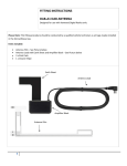
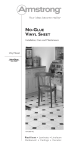
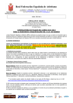
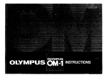
1
OPERATING INSTRUCTIONS
for
ULTIMATTE-5
ULTIMATTE
CORPORATION
18607 Topham
Reseda,
Telephone
Telex
Street
California 91335 USA
662453
818-345-5525
Ultimatte
RSDA
OCTOBER 1985
TABLE OF CONTENTS
Page
Paragraph
CHAPTER
l-l
1 - GENERAL DESCRIPTION
................
................
................
................
................
Introduction . . . . . . . . . . . . . . .
Purpose of Equipment . . . . . . .
I-2
l-3
1-4
Physical Description . . . . . . . . .
Warnings. . . . . . . . . . . . . . . . . .
l-5
Unpacking
................
CHAPTER
2
..............................
Power Supply Connections. . . . . . . . . . . . . . . . . . .
Main Unit Rear Panel . . . . . . . . . . . . . . . . . . . . . . .
Tally Connector . . . . . . . . . . . . . . . . . . . . . . . . . . .
2-5
2-6
Remote Control Rear Panel . . . . . . . . . . . . . . . . . .
Connections . . . . . . . . . . . . . . . . . . . . . . . . . . . . . .
Typical
2-8
2-9
Setup for NTSC Background . . . . . . . . . . . . . . .
Connection of Multiple Remotes . . . . . . . . . . . .
2-l 1
2-12
2-13
. . .
.
.
.
. . . .
. . .
. . .
l-l
l-l
l-l
.
.
...
.
. . .
Introduction
2-7
2-10
.
. . .
. .
. . .
. . .
l-l
l-l
- INSTALLATION
2-2
2-3
2-4
2-l
.......
.......
.......
.......
Setup . . . . . . . . . . . . . . . . . . . . . . . . . . .
Connection of Multiple Remotes and Main Units
Important Considerations . . . . . . . . . . . . . . . . . . . .
Power-up Procedure . . . . . . . . . . . . . . . . . . . . . . . .
Delay Line Adjustments . . . . . . . . . . . . . . . . . . . . .
. .
.
. . .
.
. .
. .
. . .
.
.
.
.
.
.
.
.
.
.
.
.
.
. .
.
* *
. .
. .
.
.
. . .
...
.
...
2-l
2-l
2-l
2-5
. .
. .
2-5
2-5
...
2-5
2-7
...
...
*
2-7
.
2-8
. . . .
. . . *
. . .
...
...
2-8
2-9
.
2-9
. .
. .
. .
. . . .
3-1
. . .
3-l
3-l
CHAPTER 3 - BASIC REQUIREMENTS
3-l
Introduction . . . . . . . . . . . . . . .
3-2
3-3
Cameras . . . . . . . .
Selection Criteria . . . . . .
3-4
3-5
Detail or Contour Control . .
Diffusion or Fog Filters .
3-6
3-7
3-8
Tube Focus and Beamwidth
Registration Adjustment . .
White and Black Balance .
3-9
3-10
3-l 1
3-12
3-13
3-14
3-15
Backing . . . . . . . . . . . . . . . . . .
Color Purity . . . . . . . .
Lighting the Backing . . . .
Texture
of
Backing.
3-16
Lighting . . . . . . . . . .
Amount of Light . .
3-l 7
3-18
Lighting Techniques . . . . .
Bounce
Light
.
.
.
.
3-19
Contrast
.
.
.
.
.
. . . .
.
.
.
.
.
.
Choice of Blue vs. Green . .
Ultimatte Blue Screen . .
.
.
.
.
.
.
.
I
.
.
.
.
.
.
.
.
.
.
.
.
.
.
.
.
.
.
.
.
.
.
.
.
.
.
.
.
.
.
.
.
.
. .
.
.
.
. .
. .
.
.
. . .
. .
.
. . .
. .
.
.
.
. .
. . .
.
....
....
....
.
.
. . .
.
. . .
. .
. .
. .
.
. . .
.
.
.
.
.
.
.
.
.
.
.
.
. .
.
. .
. .
. . .
. .
. . .
. . .
. .
. .
. . .
. . .
. .
3-l
3-l
3-l
3-l
. . .
3-2
3-2
....
.
.
3-2
3-2
.
.
.
3-2
3-3
.
.
.
3-3
3-4
. . .
.
3-4
3-4
....
3-4
. . .
3-4
TABLE OF CONTENTS (Core)
Page
Paragraph
3-20
3-21
3-22
3-23
3-24
Temperature . . . . . . . . . . . . . . . . .
Lighting . . . . . . . . . . . . . . . . . . . .
Polarizing Filter . . . . . . . . . . . . . . . . . . . . .
Encoders . . . . . . . . . . . . . . . . . . . . . . . . . .
Testing Encoder . . . . . . . . . . . . . . . . . . .
Color
Floor
......
......
......
.
...................
...................
...................
.
3-4
.
. 3-4
. . . . . 3-5
. . . . 3-5
. . . 3-5
. . . . . . . . . . . . . . . . . . .
CHAPTER 4 -OPERATING INSTRUCTIONS
4-1
4-2
4-3
4-4
4-5
4-12
4-19
4-25
4-29
4-34
4-38
4-42
4-47
4-48
4-54
4-55
4-59
4-65
4-69
Introduction
..................
Preparation for Use . . . . . . . . . . . .
Condensed Control I dentif ication
Detailed Control Identification . . .
FG Select . . . . . . . . . . . . . . . . . . . .
BG Select . . . . . . . . . . . . . . . . . . . .
FG Matte . . . . . . . . . . . . . . . . . . . .
FG/BG . . . . . . . . . . . . . . . . . . . . . .
FG/Color Logic . . . . . . . . . . . . . . .
FG Adjust . . . . . . . . . . . . . . . . . . .
BG Matte . . . . . . . . . . . . . . . . . . . .
BG Adjust . . . . . . . . . . . . . . . . . . .
. . .
. . . .
.
.
.
. . .
. . . . .
.
. . . .
.
.
.
. . .
.
.
BG Field. . . . . . . . . . . . . . . . . . . . .
Window . . . . . . . . . . . . . . . . . . . . .
Component Out . . . . . . . . . . . . . . .
B/WLogic . . . . . . . . . . . . . . . . . . .
Glow/Title . . . . . . . . . . . . . . . . . . .
Matte-l n . . . . . . . . . . . . . . . . . . . . .
Program/Memory . . . . . . . . . . . . . .
.
. . . . .
.
.
.
.
.
.
.
.
.
.
.
.
.
.
.
.
.
.
.
. . . .
. . . .
.
. . . .
. . .
.
. . .
. .
. .
. .
. . .
. .
. .
.
. . .
. .
...................
...................
...................
...................
...................
...................
...................
...................
...................
...................
...................
.....................
.....................
.....................
.....................
.....................
.....................
......................
. . .
4-1
4-1
....
....
4-l
4-1
. . .
....
4-5
4-6
.
.
4-6
. . .
.
.
4-8
4-9
. .
4-10
. .
4-11
4-12
...
.
4-13
4-14
. .
4-l 5
4-16
...
. .
. .
4-17
4-18
4-19
LIST OF ILLUSTRATIONS
Page
Figure No.
l-l
2-l
2-2
2-3
2-4
2-5
Ultimatte-5 System . . . . . . . . . . . . . . . . . . . . . . . . . . . .
Remote Control Unit Power Selector Switch . . . . . . . . .
Main Unit Power Selector Switches . . . . . . . . . . . . . . . .
Main Unit Rear Panel . . . . . . . . . . . . . . . . . . . . . . . . . . .
Remote Control Unit Rear Panel . . . . . . . . . . . . . . . . . .
2-6
2-7
Typical Connection of Ultimatte-5 . . . . . . . . . . . . . . . . .
Connection for NTSC Background . . . . . . . . . . . . . . . . .
Connection of Four Remotes to One Main Unit. . . . . . .
2-8
2-9
Connection of Multiple Remote and Multiple Main Units
Circuit Board F8021 . . . . . . . . . . . . . . . . . . . . . . . . . . .
3-l
4-l
4-2
Set Construction to Eliminate Hard Edge at Back Corner
Remote Control Front Panel . . . . . . . . . . . . . . . . . . . . .
Foreground Select Control Group . . . . . . . . . . . . . . . . .
4-3
4-4
Background Select Control Group . . . . . . . . . . . . . . . . .
Foreground Matte Control Group . . . . . . . . . . . . . . . . .
4-5
Foreground/Background Control
Foreground/Color Logic Control
4-6
4-7
4-8
4-9
4-10
4-l 1
Group . . . . . . . . . . . .
Group . . . . . . . . . . . . .
Group . . . . . . . . . . . . . . . . .
Foreground Adjust Control
Background Matte Control Group
.................
Background Adjust Control Group . . . . . . . . . . . . . . . . .
Background Field Control Group . . . . . . . . . . . . . . . . . .
4-12
4-13
Window Control Group . . . . . . . . . . . . . . . . . . . . . . . . .
Component Out Control Group . . . . . . . . . . . . . . . . . . .
Black/White Logic Control Group . . . . . . . . . . . . . . . . .
4-14
4-15
4-16
Glow/Title Control Group . . . . . . . . . . . . . . . . . . . . . . .
Matte-In Control Group . . . . . . . . . . . . . . . . . . . . . . . . .
Program/Memory Control Group . . . . . . . . . . . . . . . . . .
.
,
.
.
.
.
.
. .
.
. .
.
.
. .
. .
. .
.
. .
. .
.
. .
.
.
.
. .
.
.
.
.
.
.
.
.
.
.
.
.
.
.
. .
.
.
.
.
. .
.
. .
. .
.
.
.
.
.
.
.
.
.
.
.
.
.
.
.
.
.
.
.
.
.
.
.............
.............
.............
.............
.............
.............
.............
.............
.............
.............
.............
.............
.............
.............
.............
.............
.............
.............
.............
.............
.............
.............
.............
.............
.............
.
.
iv
2-l
.
.
2-2
2-4
.
2-5
2-6
.
2-6
2-7
.
2-8
2-10
.
3-3
4-2
.
4-5
4-6
.
4-7
.
.
4-8
4-9
4-10
4-l 1
4-12
4-13
4-14
4-l 5
4- 16
4-17
4-18
4-19
LIST OF TABLES
Table No.
l-l
2-l
4-l
Page
Ultimatte-5 Specifications . . . . . . . . . . . . . . . . . . . . . . .
Main Unit Rear Panel Connections . . . . . . . . . . . . . . . . .
Summary of Operating Controls and Indicators . . . . . . .
. . . .
III
REMOTE CONTROL UNIT
MAIN UNIT
Figure l-l. Ultimatte-5 System
iv
CHAPTER 1
GENERAL
1-4.
l-l. INTRODUCTION.
This is the operation manual for the Ultimatte-5
manufactured by Ultimatte Corporation, Reseda,
California. This manual is divided into four secGeneral Description, Installation, Basic
tions:
Requirements,
and
Operating
DESCRIPTION
Instructions.
A
sep-
WARNINGS.
Before
power
to
the
Ultimatte-5
unit:
1. Verify that power supply is strapped for the
power source being used (par. 2-2).
2. Do not make any internal adjustments to
potentiometers inside chassis of main unit
arate service manual is also available for the Ultimatte-5.
or remote control.
1-5.
1-2. PURPOSE OF EQUIPMENT.
connecting
UNPACKING.
for
The Ultimatte-5 is normally shipped in two packages, one containing the main unit and one con-
the production of composite video images in which
a foreground subject is superimposed on one or
taining the remote control unit. Carefully remove
the units from these two packages and inspect for
more layers of background scenes.
any damage which may have occurred during ship-
1-3.
DESCRIPTION.
ping. Check the contents of each package against
the enclosed packing list to verify that power
The Ultimatte-5 (figure 1-l) consists of two units,
cords, instruction manuals, and other accessories
are included. Notify your dealer of any discrep-
The
Ultimatte-5
PHYSICAL
is
a
linear
electronic
system
the main unit and the remote control unit. The
two units are interconnected by a single coaxial
cable. One remote control unit may be used to
provide control signals for up to four main units.
Conversely, up to four remote control units may
be connected to a single main unit. Both the main
unit and the remote control are configured for
mounting in a 19.inch electronic equipment rack.
Specifications applicable to the Ultimatte-5 are
given in table l-l.
ancies.
The blue ana green-colored cards packea with your
unit permit testing and initial setup of your unit.
These cards are painted with the pure blue and
pure green colors which should be used to paint
the backings in your studio.
A piece of polarizing filter is also included with
your unit to permit evaluation of test results when
a polarizing filter is placed over the camera lens.
1-l
Table l-l. Ultimatte-5 Specifications
Size:
Main Unit
Remote Control
19 in. wide x 7 in. high x 19 in. deep
Power Source
Both rnain unit and remote control are individually connected to a
19 in. iwide
x 7 in. high x 4 in. deep
source of ac power. Depending on internal power supply connections, this may be 115 vat 60 Hz or 230 vat 50 Hz.
Random Access Memory
Glow or Titles
32K in each main unit permits up to four control setups to be
stored for each of eight program sources.
Inserts solid or transparent glow or titles from an external character
generator.
External Matte (Key) Signal
Accepts external matte (key) signal.
Inputs
Accepts all inputs. RGB/Y
Y IQ(YUV)/NTSC(PAL).
outputs
Y RGB/Y, R-Y, B-Y/YIQ/NTSC MIX/MATTE + a n d -.
Black Burs
Requires connection of external black burst input for timing (sync).
Windows
Unit produces soft or hard-edge windows. Produces normal or
reverse windows; allows shutoff of background scene within
RGB/Y, R-Y, B-Y/Y IQ(YUV)NTSC/
window area.
Backing
Required
Matting logic for blue, green, white, and black backings.
Red by reversing blue and red cables.
Background
Matte
Automatic background matte setting. Also provides dynamic background matte tracking through color changes in backing from back
wall, through coving, to floor.
Black/White
Balance
Provides RGB black balance and RGB white balance to permit
matching of color tones in foreground and background blacks
and whites.
1-2
CHAPTER 2
INSTALLATION
2-l. INTRODUCTION.
This chapter describes a number of methods for
connecting the Ultimatte-5 into a video production
setup. All signal connections in and out of the
main unit and remote control unit are on customerprovided 75.ohm RG59/U coaxial cables terminated in BNC connectors.
2-2. POWER SUPPLY CONNECTIONS.
Units being shipped to North America are set for
115.vat power input. Those being shipped to
Europe are set for 230 vat. If it is necessary to
verify or change this:
1. On remote control back panel, loosen two ‘/4turn Dzus-type fasteners and remove panel.
2. Set remote control power selector switch
(figure 2-l ) to either 115V or 230V.
3. Replace back panel on remote control.
4. On main unit bottom panel, loosen ten %turn Dzus-type fasteners with a Phillips screwdriver and remove panel.
5. Set main unit AC POWER selector switch
(figure 2-2) to 115 or 230.
6. If power input is lower than normal, set main
unit LINE VOLTAGE selector switch (figure
2-2) to (LOW), which accommodates input
power levels of 105 or 210 vat.
7. Replace bottom panel on main unit.
2-3. MAIN UNIT REAR PANEL.
Most signal connections to and from an Ultimatte5 unit are made through the connectors on the rear
panel of the main unit. The layout of this panel is
shown in figure 2-3 and each connection is described
in table 2-1.
115Vl23OV SWITCH \
Figure 2-l. Remote Control Unit Power Selector Switch
2-l
Figure 2-2. Main Unit Power Selector Switches
Table 2-l. Main Unit Rear Panel Connections
Function
Connection
TALLY
Eight lines are connected here from the external switcher so that as each
program source (camera or recorder) is selected by the switcher, the
Ultimatte-5 can select the corresponding control settings from memory.
(See par. 2-4.)
REMOTE 1-4
’
OUTPUTS:
YRGB
Normal output signal to external encoder.
For connection to component analog tape recorder. Format is
front-panel selectable by COMPONENT OUT SELECT
switch.
Y,R-Y,B-Y or Y IQ
NTSC MIX
2-2
Permits connection of four remotes to one main unit. Unit under controt is as selected by front panel PROGRAM/MEMORY ULTIMATTE
SELECT 1-4 switches.
I
Used generally when background scene is from an NTSC or PAL source.
MATTE - o r +
Positive and negative matte signals are provided simultaneously so they
may be recorded for future processing.
WINDOW MON
When T-connected to a monitor, permits viewing window positions.
Table 2-l. Main Unit Rear Panel Connections (Cant)
Function
Connection
INPUTS:
All inputs are looped.
BLACK BURST
This signal provides all timing information required by the Ultimatte.
Sync and blanking are generated internally.
EXT WINDOW
May be used to insert a second window from the external sources.
MATTE
Accepts a recorded matte signal for reverse order of crossing and postproduction
cornpositing.
GLOW
Permits connection of titles from external character generator or
connection of glow input.
BG INPUTS:
The four background source inputs may be connected simultaneously
and then be selected by the BG SELECT switches. These are, for
example:
NTSC
An NTSC (or PAL) signal from a tape machine or camera.
YRGB
A Y RGB signal from a camera or telecine converter (or second RGB).
RGB
An RGB signal from a camera.
Y,R-Y,B-Y/YIQ(YUV
A signal from a component analog tape machine.
FG INPUTS:
Four foreground inputs may be connected simultaneously and then be
selected by the FG SELECT switches. These are, for example:
YRGB
A Y RGB signal from a camera or telecine converter (or second RGB).
RGB
An RGB signal from a camera.
Y,R-Y,B-Y/YIQ(YUV
A signal from a component analog tape machine.
NTSC MIX
Any processed foreground signal encoded to NTSC (or PAL) format may
be returned to the unit for combining with an NTSC (or PAL) background.
2-3
2-4
2-4.
TALLY
CONNECTOR.
The mating plug for the rear panel TALLY connector is supplied and is a 15-pin subminiature “D”
connector. Tally inputs to this connector from the
external switcher may be a closure to ground, a
logic level to ground, or a momentary contact to
ground. The circuitry is prioritized so that if more
10
11
Ground
Ground
12
13
Ground
Ground
14
15
Ground
Ground
2-5. REMOTE CONTROL REAR PANEL.
than one closure is received simultaneously, the
highest tally number will be displayed.
The rear panel of the remote control unit (figure
Pin number assignments on the “D” connector are:
2-4) contains four BNC connectors for connection
of control cables to up to four Ultimatte-5 main
1
2
Camera 1
3
Camera 3
Camera 4
4
5
6
7
8
9
Camera 2
Camera 5
Camera 6
units.
2-6.
CONNECTIONS.
Methods of connecting the Ultimatte-5 are shown
in figures 2-5 through 2-8. Each setup is described
in the following paragraphs.
Camera 7
Camera 8
Ground
2-7. TYPICAL SETUP. (See figure 2-5.) In the typical setup, the Ultimatte-5 processes a foreground
Figure 2-4. Remote Control Unit Rear Panel
2-5
REMOTE
CONTROL
UNIT
t
FOREGROUND
INPUT
BLACK BURST
BACKGROUND
INPUT
RG
B---c
c
R---+
G
-
OUTPUT
NTSC
MAIN
UNIT
EXTERNAL
+
.---B---
OR
PAL
OUTPUT
Bd
Figure 2-5. Typical Connection of Ultimatte-5
FOREGROUND
INPUT
MAIN
UNIT
BLACK
BURST------d
BACKGROUND NTSC
INPUT
NTSC (PAL) MIX OUTPUT
Figure 2-6. Connection for NTSC Background
2-6
-
scene and a background scene to produce an RGB
composite output to an external encoder. The
encoder further processes the signals to a video
processed, then encoded to an NTSC format and
then mixed with the background to obtain an
NTSC
composite.
recorder format such as NTSC or PAL.
As in figure 2-6, foreground input could be in any
Note that all input and output connections are
selectable format with an RGB output to the external encoder. The encoder produces a composite in
made to the rear panel of the main unit, which is
connected to the remote control unit by a single
the same format as the background, which is mixed
coaxial cable. Black burst is always required for
timing information. The foreground input shown
in the Ultimatte-5 to produce the composite NTSC
(PAL) MIX output signal.
as RGB could be in any of the alternate formats
such as Y RGB/Y, R-Y, B-Y/YIQ/or YUV.
2-9.
Similarly, the background input and Ultimatte-5
output signals could be in any of the selectable
formats, as desired.
2-8.
SETUP
FOR
NTSC
BACKGROUND.
(See
figure 2-6.) When the background scene is from an
NTSC (or PAL) source, the foreground scene is
CONNECTION
OF
MULTIPLE
REMOTES.
(See figure 2-7.) One main unit may be controlled
by one, two, three, or four remote control units
on a priority basis. This makes it possible to control a single main unit from one to four locations
(stages) with a corresponding reduction in equipment duplication.
The priority is established by connection to the
main unit. The remote connected to main unit
MAIN
UNIT
Figure 2-7. Connection of Four Remotes to One Main Unit
2-7
REMOTE 1 connector will have priority whenever
it is selected. Selection is made by enabling the
correspondingPROGRAM/MEMORY ULTIMATTE
SELECT I-4 switch on the front panel of the remote control. If the ULTIMATTE SELECT switch
on remote control 1 is deselected, control reverts
to remote control 2, then in turn to remote con
trol 3 and remote control 4.
one main unit would be the input to the other so
that the composite created at the first level becomes the background for the second level. If the
same person is used as the foreground subject in
two successive levels, he will appear as “twins” in
the final composite.
2-l
1.
IMPORTANT
CONSIDERATIONS.
Many factors contribute to picture quality (as will
Z-10. CONNECTION OF MULTIPLE REMOTES
AND MAIN UNITS. (See figure 2-8.) The Ulti-
be discussed in the next chapter). In terms of
connections:
matte-5 system has the capability for one remote
control unit to control up to four main units and
1. It is important that the R, G, and B input and
for one main unit to be controlled by up to four
remotes. While it is unlikely that the setup shown
output cables be of the same type and be of
equal length.
in figure 2-8 would be used, some combinations of
multiple units are frequently desirable.
2. It is important that the timing relationship
between background and foreground scenes
When making a two-level mix, one remote may
be within 0.5 microsecond of one another and
within 1.0 microsecond of black burst (par.
control two main units. In this case, the output of
2-13).
Figure 2-8. Connection of Multiple Remote and Multiple Main Units
2-8
3. During initial setup, route RGB from camera
directly to the Ultimatte-5, not through the
external switcher. Once a good output is obtained from Ultimatte, the switcher can be
cabled in and the results compared.
2. Provide a 75% grey NTSC background from
external switcher.
3. Ohserve output of Ultimatte-5 on a picture
monitor and on a waveform monitor (if available).
4. It is recommended that all unused inputs to
the main unit be terminated with a 75.ohm
load.
2-12.
POWER-UP
white stripe foreground.
PROCEDURE.
Do not power-up the Ultimatte-5
without first
having connected black burst or the power-up circuitry will not function properly.
1 . Connect black burst to main unit rear panel
BLACK BURST INPUT.
2 . Connect coax cable from main unit to remote
control
unit.
3 . Plug in remote control to ac line.
4 . Plug main unit into ac line.
2-13.
DELAY
LINE
4. Adjust delay lines (as described below) to
eliminate any vertical black line which may be
observed adjacent to either side of vertical
ADJUSTMENTS.
When using an NTSC format background, it may
be necessary to make an internal adjustment to the
delay lines in order to obtain proper timing of foreground and matte signal. Do this adjustment with
power on, after the system is in operation and has
been satisfactorily checked out otherwise.
1. Aim camera at a blue screen with a white
vertical stripe on it (such as a piece of adding
machine tape) so that part of blue backing is
visible on both side of the white stripe.
a . Loosen ten X-turn Dzus-type fasteners
from top cover of main unit with Phillips
screwdriver and remove top cover.
b. Release the three X-turn fasteners that lock
top circuit board in place and hinge it back
out of the way to gain access to second circuit board (F8021).
C Adjust the six delay lines (figure 2-9) by
simultaneously moving both input and output jumpers on each delay line from OUT
to IN or vice versa.
NOTE
The delay line on left of figure 2-9 will
have the greatest effect; the one on the
right (with only one jumper) will have
the least effect on the output.
d. Attempt to obtain equal white or black
lines on each side of white stripe.
5. Reassemble unit and remove any test connections.
2-9
Figure 2-9. Circuit Boar-d F8021
2-10
CHAPTER 3
BASIC
REQUIREMENTS
3-1. INTRODUCTION.
high quality will produce a better picture than a
camera equipped with a zoom lens. Anyone doing
The Ultimatte-5 is essentially a “transparent”
composite work will save substantial setup time
using a set of fixed prime lenses, as there will be
device. It performs additions, subtractions, and
multiplications of the signals applied to it, but the
much less difficulty in judging perspective through
final output is always a product of the inputs.
Thus, the other factors which affect picture qual-
a fixed lens.
ity are equally as important as the Ultimatte in
determining the quality of the final composite
3-4.
image. This chapter discusses the requirements for
such related components as cameras, backings,
camera in use to prevent excessive “edginess” on
foreground images. A moderate edge on the image
lighting, filters, and encoders.
is quite acceptable when observed from the proper
viewing distance, but excessive edginess will defeat
3-2.
the
CAMERAS.
DETAIL OR CONTOUR CONTROL. Carefully adjust the detail or contour control on the
by
natural-looking
the
composite
normally
produced
Ultimatte-5.
The higher the quality of the signal going into the
Ultimatte, the higher will be the quality of the output. The limitation of the Ultimatte to composite
3-5. DIFFUSION OR FOG FILTERS. When
an image is the limitation of the camera to resolve
diffusion filters or fog filters not be used. These
filters introduce excessive noise into the composite
that image.
Since the Ultimatte operates on the R-G-B components of the video signal, it is important that the
camera have relatively quiet signals on all three
channels (high signal-to-noise ratios). It is possible
shooting composite images, it is recommended that
image with the result that foreground figures bleed
into blue backings, or vice versa. Black objects may
acquire a blue tint. If these filters are used, the results must be examined with great care and adjustments made where necessary.
to have a camera which produces a relatively
acceptable encoded picture but which has a large
amount of noise on one channel. After processing
in the Ultimatte, that noise may deteriorate the
final composite to a greater extent. Most cameras
will produce acceptable results under good conditions. It is when conditions are less than ideal that
the differences among cameras become more
noticeable.
These
conditions
include
3-6. TUBE FOCUS AND BEAMWIDTH. If one of
the camera’s color tubes is slightly out of focus,
fringing may occur, particularly in longer shots. If
the beamwidths of the three tubes differ, edging
may be observed on the leading and trailing edges
of moving objects. Make sure the camera is in good
adjustment at all times.
inadequate
lighting, forward-falling shadows, and excessive
black gloss.
3-7.
3-3. SELECTION CRITERIA. In selecting among
direct monitor, but the registration differences will
several cameras, first select the one that has the
be greatly magnified by the cornpositing process.
The Ultimatte recognizes a color edge as the loca-
best color registration of all three channels. Next
select the one that is the most quiet on all three
channels. A camera equipped with a fixed lens of
REGISTRATION
ADJUSTMENT.
A
camera
with minor registration differences between the
three tubes may produce an acceptable image on a
tion of an object; thus, a registration error is the
same as a physical displacement of that object.
3-l
This will be recognized from the presence of oppos-
well the unit works and what the backing color
ing color fringes on the opposite edges of fore-
should be.
ground objects.
3-8. WHITE AND BLACK BALANCE. It
is important that the camera be properly white balanced
and black balanced. When the camera is irised up
and down, the white should track through grey and
To evaluate blue backings painted with other
paints, place a white card against it and shoot the
card and a portion of the backing. With the white
set at 100 units of video, the blue content of the
backing should be 70 units minimum, the green
through-the-lens
content of the backing should be 35 units maxi-
teleprompter is being used, it should be switched
on during the white and black balancing proce-
mum, and the red content of the backing should be
25 units maximum. While some acceptable backings
dures. If a white card is being used for white balance and placed near the blue screen, it should be
have been made with other than Ultimatte blue
paint, the green backing is much more difficult to
placed so that blue bounce light from the backing
will not fall on it and cause color distortions.
achieve with commercial paint.
blacks
should
remain
black.
If
a
3-9. BACKING.
The backing is the painted screen in front of which
foreground subjects are photographed. It is most
often blue, but may also be green, white, or black.
Black and white are primarily used in the production of animated objects. The term “backing” is
separate and distinct from the term “background.”
Background refers to the background scene which
is cornposited with the foreground subjects to produce the final product.
3-10. COLOR PURITY. Ultimatte is a linear system
for
cornpositing
images.
Unlike
chroma-key,
which is a switching system, Ultimatte will provide
a composite in all areas of the backing from those
which are fully illuminated down into deep shadows. Therefore, the backing color must be uniquely
reflective. For this reason, special blue and green
paints have been developed and are available from
Rosco Laboratories, Inc., Port Chester, New York
(and other cities). The blue paint has a very high
Be extremely careful of paints that burnish when
touched, especially if it is necessary to walk on the
backing, as burnish marks will show through as defects in the final image.
3-11. LIGHTING THE BACKING. When there is
enough separation to do so, place blue gels on the
lights illuminating the blue screen and use white
lights on the foreground subject. This will improve
the quality of the light from the backing. It is even
possible to use a white backing illuminated only by
blue filtered light. It is not recommended that
backlighted blue transmission screens be used with
Ultimatte, as edging and loss of foreground image
may resu It.
3-12. TEXTURE OF BACKING. The most important requirement for obtaining a quality composite
is a backing of uniform color quality. Any defects
in the backing such as seams, wrinkles, scuff marks,
or a change in texture from wall to cove to floor
will be seen as differences in background intensity
when the composite is made.
blue reflectance and a very low green reflectance
One method of set construction which is useful in
(vice versa for the green). The use of this paint is
highly recommended. (Also see paragraph 3-14.)
eliminating hard shadows or texture changes at the
junction of horizontal and vertical surfaces is
The sample card enclosed with the Ultimatte-5
shown in figure 3-l. Since there is no actual corner,
there will be a minimal difference in reflection
should be used in initial tests to demonstrate how
from the two surfaces.
3-2
3-13. CHOICE OF BLUE VS. GREEN. The choice
of blue versus green backing is determined by the
presence of a detail edge from the camera’s detail
generator. If a white or yellow foreground subject
is being composited with a light-colored background scene, the camera may produce a hard detail edge when photographing the foreground
against a blue backing. In this case, a green backing
or wardrobe) is too close to the color of the backing. Distortions may result from the substantial
signal processing required to discriminate these
colors. Switching to a backing of contrasting color
solves the problem. Comparison of results with
both color backings may be desirable in making
the optimum decision.
would solve the problem, resulting in a more
Red backings may be used for product shots if
natural-looking
there is no red in the foreground image. However,
where people are involved, the use of red backings
composite.
Conversely, a dark foreground subject being combined with a dark background would photograph
more naturally against a blue backing. When there
is a substantial contrast between foreground and
background subjects (dark against light or light
against dark), either backing color will be acceptable.
is inadvisable. If a red backing is used for a product
shot, reverse the red and blue cable connections for
both the input and the output.
3-14. ULTIMATTE
BLUE SCREEN. A flexible
plastic sheeting has been developed which can be
rolled up and down or stretched in a frame. This
material has such a high blue reflectance that a
A second reason for changing backing color is
when the color of a foreground object (solid object
wide range of subjects may be composited in front
of it. It is recommended for difficult scenes and is
VERTICAL SURFACE OF SET
GAP ----,
Fd
HORIZONTAL SURFACE OF SET
Figure 3-I. Set Construction to Eliminate Hard Edge at Back Corner
3-3
available in sizes up to 40x100 feet from Stewart
Filmscreen Corp., Torrance, California. To date,
no blue or green paper has been found suitable as
3-18. BOUNCE LIGHT. When setting up a shot,
backing
processed, the backing and most of the bounce
material.
some bounce light from the backing will light up
the edges of the subject, yet when the image is
3-15. LIGHTING.
light from it will be suppressed to black. Think of
the backing as a piece of black velvet which reflects
no light. Also think about the background scene. If
In general, the proper lighting occurs when the
amount of incident light (in foot candles) on the
it is light and would be expected to light up a subject in front of it, probably more sidelighting of
backing is the same as the arnount of incident light
the subject is necessary. This is best produced by
on the subject. However, the amount of light used
is much greater than with normal photography.
two light sources, at approximately head level.
With a dark background, this sidelighting would
not be desirable.
3-16.
AMOUNT OF LIGHT. Composite photography in front of a blue screen requires two to
three times more light than normal photography.
Lens vignetting cannot be tolerated, as it interferes
with window generation and other compositing
functions and aggravates noise problems. This is
Had the subject actually existed as an element in the
background scene (rather than being composited
into it), whatever brightness existed in the background scene would have illuminated the sides and
back of the subject. The blue backing does not pro-
less likely to occur at smaller apertures made pos-
vide the backlight the scene would have provided
sible by higher light levels.
and backlighting must therefore be added on the
set.
As discussed later in this chapter, there are times
when it is desirable to use polarizing filters. These
3-19.
CONTRAST.
filters cut down some of the light to the camera
tubes so more light helps to compensate.
Approximate contrast between
lighting of foreground and background subjects
should be accomplished by adjustment of lighting
3-17. LIGHTING TECHNIQUES. W h e n l i g h t i n g
on the foreground scene. The Ultimatte-5 contains
a FG CONTRAST control which can be used to
the set, it must be kept in mind that the amount of
add contrast to the foreground subject.
light on the backing will determine the extent to
which the background scene is lighted in the com-
3-20. COLOR TEMPERATURE. Never use straw-
posite.
colored filters when lighting a foreground subject.
When a key-light shadow is important, start by
lighting the set with the key light. Orient the key
light to cast a shadow in the same direction as the
shadows in the background scene. Then add light
as needed to illuminate the backing, being careful
not to completely wash out the key light shadow.
Only white light is needed. Do not mix the color
temperatures of lamps used to light the backing, as
this will result in color tinting of the background
scene. Lights with a color temperature of 5600°K
or 3200° K a r e a c c e p t a b l e w i t h b l u e b a c k i n g s .
A blue-colored light should not be used on a foreground subject, as it will cause the subject to be-
The intensity of the shadow is thus controlled by
the amount of fill added to that shadow. Again,
come
consider the intensity of the background shadows
3-21. FLOOR LIGHTING. T h e f l o o r s h o u l d b e
when making this decision.
iighted frorn sources near the camera rather than
3-4.
transparent.
from overhead lights. Overhead lights may produce
3-23.
a glare which the camera will see as white light, and
this will appear as flare in the composite.
The final picture quality is dependent on the qual-
3-22.
ity of the encoder used. Always use a broadcastquality video-type encoder to prevent deteriora-
POLARIZING
FILTER.
The use of the polarizing filter can solve certain
problems that will arise with backlighting and with
reflective subjects. Floor glare, as mentioned earlier, can result in an unwanted white haze in the
final
composite.
ENCODERS.
tion of the final product.
3-24. TESTING ENCODER. When an encoder has
been selected for use, it is recommended that it be
tested to evaluate the output quality. Connect the
RGB from the camera to the input of the encoder,
rotate it until the glare disappears. The use of pol-
then connect the output of the encoder to the A
side of a monitor. Connect the camera’s internal
arizing filters on shiny product shots such as automobiles may eliminate the need for deglossing
encoder output to the B side of the monitor. Switch
between the two to assure that the external encoder
spray.
is at least as good as the camera’s internal encoder.
Polarizing filters are supposedly of neutral density,
but frequently are not. It is best to white balance
If the external encoder cannot be adjusted to per-
Mount the polarizing filter on the camera lens and
the camera again with these filters in place. When
using a polarizing filter, it is necessary to open the
form satisfactorily, the user must accept the fact
that the encoder, not the Ultimatte-5, is limiting
camera lens one to one-and-one-half stops. This is
the final picture quality. This same test should be
made with the switcher in and out of the circuit to
the reason for using high illumination on the set.
evaluate its quality also.
3-5/(3-6
blank)
CHAPTER 4
OPERATING
INSTRUCTIONS
to any position. Before starting operations for a
new setup, adjust all controls to their index posi-
4-l. INTRODUCTION.
This chapter contains the information required to
operate the Ultimatte-5. Each of the 15 control
groups on the remote control panel is discussed in
detail and the function of each switch or control
(potentiometer) is described. There is no standard
operating procedure. The Ultimatte-5 is extremely
tion and set all switches so that the red indicators
are off (to the extent possible).
4-3.
CONDENSED CONTROL
IDENTIFICATION.
versatile and facilitates opera.tion in a broad variety
of situations. It is up to each operator to determine
the ideal operating sequence for each application.
The operating panel of the Ultimatte-5 is shown in
figure 4-l. Table 4-l is a condensed explanation of
4-2 PREPARATION FOR USE.
4-4.
When the Ultimatte-5 is connected to a power
source, it will come on with most switches in their
The balance of this chapter contains detailed de-
neutral positions. However, controls may be set
larged illustration of the controls in each group.
the function of each control.
DETAILED
CONTROL
IDENTIFICATION.
scriptions of each control group keyed to an en-
Table 4-l. Summary of Operating Controls and Indicators
Group Name
Control
Name
Function
FG SELECT
RGB switch
Selects an RGB foreground input.
Y RGB switch
Y/R-Y/B-Y switch
Selects a Y RGB foreground input.
YlQ(YUV)
switch
Selects a Y/R-Y/B-Y foreground input.
Selects a Y IQ or YUV foreground input.
BACKING COLOR switch
FG ONLY switch
Selects logic for blue or green backing.
Permits only foreground image to be viewed.
BG SELECT
RGB switch
Selects an RGB background input.
Y RGB switch
Y/R-Y/B-Y switch
Selects a YRGB background input.
Selects a Y/R-Y/B-Y background input.
YlQ(YUV)
Selects a Y IQ or YUV background input.
switch
NTSC(PAL)
switch
BG ONLY switch
Selects an NTSC (or PAL) background input.
Permits only background image to be viewed.
MATTE SET switch
Provides silhouette against neutral field for setting
density of foreground matte.
MATTE DENSITY control
Sets matte density appropriate to transparency of
FG MATTE
subject.
4-1
4-2
Table 4-l. Summary of Operating Controls and Indicators (Cant)
r
'1
Group Name
Control
Name
Function
FG MATTE
MATTE DENSITY BAL
Optimizes matte density for certain foreground
(cant)
control
BLACK GLOSS control
colors.
Prevents print-through on dark glossy objects.
Permits use of backings with less-than-perfect color
BACKING PURITY control
balance.
FGiBG
CLEAN-UP control
Allows progressive removal of unwanted foreground
detail and backing imperfections.
FADE/MIX
control
Permits foreground to be faded out or FG/BG mix.
Proportions foreground removal and background
BALANCE control
replacement when using CLEAN-UP control.
FG COLOR
LOGIC
GATE 1 control
Permits reproduction of blue in foreground subject
GATE 2 control
(blue backing).
Permits reproduction of magenta in foreground
GATE 3 control
subject (blue backing).
Eliminates blue flare on green foreground subjects
(blue
backing).
WHITE BALANCE control
Permits adjustment of whites in foreground to
match whites in background.
FG LEVEL control
FG CONTRAST control
Provides control of foreground level.
Adjusts contrast of foreground subject.
BLACK RGB/WHITE
controls
Permit adjustment of black and white balance to
neutral or to match background.
FG ADJUST
RGB
BG MATTE
VERT
TRACK
ENABLE
switch
RATE control
VEIL COLOR RGB
BG ADJUST
controls
BG LEVEL BAL control
Enables a dynamic background matte that tracks
backing changes.
Adjusts how tightly backing changes are tracked.
Permit
elimination
or
introduction
of
veiling.
Sets level for background turn-on signal.
BG LEVEL control
SHADOW control
Sets clip for background turn-on signal.
BG DE FOCUS control
Simulates follow focus when subject approaches
Retains forward-falling floor shadows and enhances
shadow detail.
camera, and for normal-appearing closeups.
BG FIELD
SELECT switch
LEVEL control
Replaces background video with flat field.
Adjusts level of flat field.
COLOR
Set color of flat field.
RGB
controls
4-3
Table 4-l. Summary of Operating Controls and Indicators (Cant)
Group Name
Control
Function
Name
WINDOW
I NT +/- switch
Permits window to be a frame (+) surrounding the
INT N/R switch
subject or an area (-1 which may be placed anywhere.
Reverse (R) shuts off background scene in window
area.
EXT N/R switch
Selects normal (N) or reverse (RI for external
window input.
HOLD BLU/GRN switch
Permits holding original blue (or green) color of blue
LEFT/RIGHT/TOP/
BOTTOM controls
object or reflection within reverse window area.
Set each window edge as desired. Complete cw
rotation changes from hard edge to soft and vice
versa.
COMPONENT
OUT
SELECT
Selects output format of OUTPUTS connectors for
switch
use with component analog recorder.
B/W LOGIC
B/W logic select switch
Sets up logic to composite for either a black or
MASTER
white backing.
Sets threshold at which objects begin to become
DENSITY
DENSITY R/G/B controls
transparent.
Permit threshold to be set for each color independently without affecting subject color or brightness,
GLOW/TITLE
MASTER LEVEL control
R/G/B controls
DENSITY control
FRONT/REAR
control
Sets level of brightness of glow or title.
Set color of glow or title.
Sets degree of transparency of glow or title. Glow
covers or emanates only from edges.
Places titles in front of or behind foreground subject,
MATTE IN
PROGRAM/
MEMORY
INVERT switch
Used for reverse order of crossing.
PE D control
LEVEL control
Eliminates setup when used.
Compensates for low-level recording
ULTIMATTE SELECT 1-4
Select one of four Ultimatte-5 main units which will
switches
be controlled by remote control unit.
TALLY indicator
F I LE 1-4 switches
Indicates program source selected by switcher.
Select one of four previously established setups
MEMORY switch
from memory.
In SET, all controls and switches are live and access
memory. On HOLD, unit operates from memory,
with
4-4
exceptions.
4-5. FG SELECT.
(See figure 4-Z.)
4-7. Y RGB. The luminance-red-green-blue input is
from a Rank Cintel scanner, telecine camera, or
other device connected to the Y-R-G-B
input con-
The six foreground select switches are used to configure the unit as desired to process the foreground
nectors on the rear panel. This channel may also be
used as a second RGB channel with nothing con
scene. One of the first four mutually exclusive
input selectors is pressed to select the type of fore-
netted
ground input signal to be used from among those
connected to the FG INPUTS connectors on the
rear panel of the main unit. The BACKING
COLOR switch is set to configure the logic of the
unit to the backing color in use and the FG ONLY
switch is enabled as desired.
All pushbutton selections change during the vertical interval. The remote control may be used as a
vertical interval switcher to switch, for instance,
from a camera source to a tape player source by
selecting the input source desired. The transition
will occur during the vertical interval.
to the “Y” input connector.
4-8. Y, R-Y, B-Y. The luminance (y), red minus y,
blue minus y input is normally from a composite
analog tape recorder, camera, or other device connected to the Y, R-Y, B-Y input connectors on the
rear panel.
4-9. YIQ (YUV).
The Y IQ (or YUV) input is se-
lected when a signal source of this format is connected to the YIQ input connectors on rear panel.
4-10. BACKING COLOR. The backing color switch
can be set to B to configure the unit for a blue
backing color or to G to configure the unit for a
green backing color.
4-l 1. FG ONLY. The foreground only switch is
4-6. RGB. T h e r e d - g r e e n - b l u e i n p u t i s n o r m a l l y
from a television camera connected to the R-G-B
input connectors on the rear panel.
used to remove the background scene from the
output signal so that foreground only may be
viewed.
Figure 4-2. Foreground Select Control Group
4-5
Figure 4-3. Background Select Control Group
4-12. BG SELECT. (See figure 4-3.)
The six background select switches are used to
configure the unit as desired to process the background scene. One of the first mutually exclusive
input selectors is pressed to select the type of
background input signal to be used from among
those connected to the BG INPUTS connectors on
the rear panel of the main unit. The BG ONLY
switch is enabled as desired. All pushbutton selections change during the vertical interval.
4-16. YIQ (YUV). The YIQ (or YUV) input may
be selected when a signal source of this format is
connected to the Y IQ input connectors on the rear
panel.
4-17. NTSC (PAL). The National Television Standards Committee (NTSC) or European system Phase
Alternating Line (PAL) input may be selected when
a tape recorder or any other encoded video source
in this format is connected to the NTSC input connectors on the rear panel.
4-13. RGB. The red-green-blue input is normally
from a television camera connected to the R-G-B
4-18. BG ONLY. The background only switch is
input connectors on the rear panel.
used to remove the foreground scene from the output signal so that background only may be viewed.
4-14. Y RGB. The luminance-red-green-blue input
is from a Rank Cintel scanner, telecine camera, or
other device connected to the Y-R-G-B input connectors on the rear panel. This channel may also
be used as a second RGB channel with nothing
connected to the “Y” input connector.
4-19. FG MATTE. (See figure 4-4.)
The foreground matte controls are used to adjust
density of the foreground matte, which will optimize the foreground in the final composite output.
4-15. Y, R-Y, B-Y. The luminance (y), red minusy,
4-20. MATTE SET. When enabled, the matte set
blue minus y input is normally from acomponent
switch causes the foreground subject to appear as
analog tape recorder, camera, or other device
connected to the Y, R-Y, B-Y input connectors on
a black silhouette against an internally generated
white field for the purpose of adjusting the other
controls in this control group.
the rear panel.
4-6
Figure
4-4.
Foreground
Matte
Control
Group
4-21. MATTE DENSITY. The matte density con-
4-23. BACKING PURITY. The backing purity
trol is used to adjust density of the foreground sub-
control is normally set to HI when using the recom-
ject from transparent (ccw) to extremely opaque
(cw). in use, this control is first set fully ccw. It is
mended backing paints (par. 3-10).
then turned clockwise until the entire subject silhouette just becomes opaque, but where semi-
purity, it is set between HI and LO as necessary to
obtain a background scene turn-on signal.
transparent areas of the subject remain semitransparent. If this control is advanced too far,
dark edges may appear around the foreground
subject.
4-22. MATTE DENSITY BAL. The matte density
balance control is used to improve the edge characteristics of certain colors (mainly reds and greens).
However, if a
backing is in use which does not have good color
For instance, when using a high-quality blue backing, the unit will recognize and properly composite
cyan and magenta tones in the foreground subject.
If the backing is of lesser color purity, such as
cyan or magenta, good cornpositing can still be
accomplished by turning this control toward LO,
Normally a matte edge is achieved too soon on red
subjects.
Therefore, i f t h e f o r e g r o u n d s c e n e i s
and avoiding the use of cyan and magenta wardrobe.
mainly of people’s faces (predominantly red flesh
tones), adjust this control in the ccw direction to
drop some of the red from the turn-on signal.
4-24. BLACK GLOSS. The black gloss control is
If the scene is of green foliage, adjust this control
cw to drop some of the green from the turn-on
signal. Where both reds and greens appear in the
foreground scene, adjust the control for optimum
edge characteristics on the most important elements in the scene.
adjusted to prevent dark, shiny objects in the foreground scene from appearing transparent. The use
of this control will also increase the density of
shadows cast by the foreground subject. Use this
control only when necessary or shadows may be
accented unnaturally and edges may start to appear
hard.
4-7
Figure
4-5.
Foreground/Background
Control
Group
FADE MIX
4-25. FG/BG. (See figure 4-5.)
The
controls
in
the
foreground/background
4-27. FADE/MIX. The fade/mix control has two
group
are used to adjust the relative densities or importance of the foreground subject as opposed to the
background scene.
4-26. CLEAN-UP. T h e c l e a n - u p c o n t r o l c a n b e
adjusted to cause the background scene to turn on
sooner than it would ordinarily while simultaneously partially turning off the foreground subject
in its most transparent areas. This is useful for removal of unwanted foreground detail such as support wires or footprints and for removal of backing
imperfections such as seams or joints.
functions, depending on the position of the FG
SELECT/FG ONLY switch (par. 4-5/4-l 1). When
FG ONLY is off, this control is in the fade mode
and when FG ONLY is on, it is in the mix mode.
In the fade mode, the fade/mix control may be
adjusted to gradually fade out the foreground subject, ultimately leaving only the background scene
in the output.
In the mix mode, both the foreground and background subjects fully appear in the output superimposed on one another. The relative strength of
Also, if the backing contains a seam or wrinkle
the two scenes is determined by rotation of the
control. This mode is useful for arranging set pieces
which is visible in the composite output, the cleanup control can be adjusted to remove this seam or
in the foreground so that they match objects in the
background scene.
wrinkle.
4-28.
The clean-up control should be moved from its
index marks only when necessary for the types of
conditions described above, as use of this adjustment removes fine-edge detail from the image.
4-a
BALANCE.
The balance control proportions
the clean-up between the FG and BG and should
be adjusted with each increment of clean-up to
obtain the most pleasing picture. (The balance control also affects the fade/mix function.)
Figure 4-6. Foreground/Color Logic Control Group
WHITE
BALANCE
4-29. FGKOLOR
. GATE 3
LOGIC. (See figure 4-6.)
The controls in the foreground color logic group
permit adjustments to be made so that specific
colors in the foreground subject can be reproduced naturally in spite of technical difficulties
which might otherwise interfere with natural
reproduction.
4-30. GATE 1. The gate 1 control is adjusted to
permit blues in the foreground subject to be reproduced when using a blue backing (otherwise blue
foreground objects will appear cyan).
Gate 1 allows the blue of R-G-B to rise above
green to the extent that green was above red. Thus,
a blue shirt on the foreground subject will remain
blue, because in a blue shirt there is more green
than red. However, blue light from the backing
failing on a white shirt will not be seen as blue
flare because green did not rise above red in the
lighting of the white shirt. There is a slight increase in noise level when using gate 1, 2, or 3.
In the case of green backing, gate 1 permits greens
in the foreground subject to be reproduced.
4-31. GATE 2. The gate 2 control is adjusted to
permit magentas in the foreground subject to be
reproduced when using a blue backing. Gate 2
allows the blue of R-G-B to rise above green to the
extent that red was above green. When gate 2 is
open, facial tones may have a slight purplish cast
to them. Gate 2 is used only when purple (magenta)
is important in the wardrobe or foreground subject.
In the case of a green backing, gate 2 permits yellows in the foreground subject to be reproduced.
4-32. GATE 3. The gate 3 control is adjusted to
eliminate blue flare on green foreground subjects
(such as plants) when using blue backing. Gate 3
prevents the blue of R-G-B from rising above the
lower of red or green. When gate 3 is in use, cyan
and blue colors in the foreground scene will be distorted to a greenish cast, and thus should be used
only when reproducing green plants against a blue
backing. In the case of a green backing, gate 3 prevents a cyan flare on blue foreground objects.
4-33. VVHITE BALANCE. The white balance control permits adjustments of maximum blue of foreground subject whites to match background white.
In the index position, blue of R-G-B is made equal
to R-G-B for white; however, if a foreground subject has light blonde hair which is reproducing
nearly white, this control may be adjusted for more
natural reproduction of hair color. This will also
result in somewhat warmer than normal white
tones on other white objects in the foreground.
4-9
l
Figure 4-7. Foreground Adjust Control Group
LEVEL
G
FG
CONTRAST
3
BLACK
WHITE
4-34. FG ADJUST.
(See figure 4-7.)
The foreground adjust group contains eight controls for the purpose of achieving special adjustments to the level, contrast, and color balance of
the foreground subject. They do not affect matting
functions or background picture.
4-35. FG LEVEL. The foreground level control
permits adjustment of the level of the foreground
scene relative to the level of the background scene.
For instance, when simulating night scenes, a reduction in foreground level may be desired. At
other times, this control may be manipulated to
match the overall appearance of the foreground to
that of the background.
4-36. FG CONTRAST. The foreground contrast
control increases contrast of the foreground sub-
4-10
ject by making dark areas even darker. It is especially useful in simulating night scenes. It may also
be used to match sunlit backgrounds or to increase
foreground contrast to match the contrast of the
background tape.
4-37. BLACK RGB-WHITE RGB. The black
R-G-B and white R-G-B controls permit the color
mix of black and/or white subjects in the foreground to be matched to that of similar objects in
the background. This color matching of foreground/
background
whites
and
foreground/background
blacks is vital to a realistic-looking composite.
It is more desirable to make these adjustments in
the Ultimatte-5 than in the camera, as the camera
color controls should always be left at standardized
levels. These controls are somewhat interactive and
black should be matched before white.
Figure
4-38. BG MATTE. (See figure 4-8.)
The background matte comprises those circuit
functions which cause the colors in the blue backing to be reduced to zero. Thus, the backing area
which was blue will now appear to be black and
the background scene can then be superimposed in
this black area. This background matte is set automatically by the Ultimatte-5 as a function of the
backing color and brightness.
The background matte controls are used to make
manual override adjustments to the automatic
adjustments.
4-39. VEIL COLOR/f?GB.
When excessive noise
appears on one color channel, a red, green, or blue
veiling may appear on the background scene. This
can be eliminated by adjustment of the corresponding veil color control.
In order to simulate underwater scenes or to en
hance reflections on glass, green veiling may be
4-8.
Background
Matte
Control
Group
4-40. VERT TRACK ENABLE. When using a backing which is a vertical wall at right angles to the
camera, plus a floor which is at an oblique angle to
the camera, the difference in camera angle to the
two surfaces may produce a white haze or veiling
in the floor area. This condition can be compensated for with the vertical track enable switch in
conjunction with the rate control.
The rate control is advanced just until the milky
veil disappears from the floor area, thus resetting
the matte on a line-by-line basis from wall to floor
to eliminate veiling. This technique retains all of
the resolution the camera had before this correction and is superior to using the veil color controls
alone.
4-41. RATE. T h e r a t e c o n t r o l a d j u s t s d y n a m i c
tracking as to how tightly backing changes are
tracked (see previous paragraph). Before engaging
added to the scene. Other similar effects are
the vertical track and rate controls, the BG adjust
shadow control (par. 4-45) should first be adjusted
possible.
to eliminate as much veiling as possible.
4-11
I____^ 86 ADJUST -
86
LEVEL
BAIL
BG
LEVEL
Figure
4-9.
Background
Adjust
Control
Group
adjustment of the BG level balance control in order
4-42. BG ADJUST.
to make the window edges invisible.
(See figure 4-9.)
4-45. SHADOW. The shadow control is used when
The background adjust group contains four controls which are used to achieve adjustments of the
background: level, balance, shadow, and focus.
4-43.
BG
LEVEL.
The
background
level
control
permits adjustment of the level of the background
scene relative to the level of the foreground scene.
This may be useful in simulating night scenes or
in matching overall appearance of background and
foreground.
the subject is backlighted or is casting a visible
shadow. Because the shadow area is below clipping
ievel, any noise in the camera tends to occur in the
shadow. The shadow control substitutes a second
control signal in the shadow area which causes the
shadow noise to be reduced by 9 to 12 dB.
Further,
in
backlighted
situations
where
glare
is
present, the glare would ordinarily obliterate the
shadow or invert it. The shadow control will, in
this situation, remove the glare, causing the shadow
to be fully visible and darker than its surroundings,
4-44. BG LEVEL BAL. T h e b a c k i n g m a y n o t
always be uniformly illuminated, yet the brightness
4-46. BG DEFOCUS. The background defocus
of the backing produces a linear signal which turns
on the background picture in proportion to the
control does not function with NTSC or PAL backgrounds. It does function with RGB, YRGB, and
brightness
level
component signals. It progressively limits the band-
balance control may be used to change the level at
which variations in backing brightness affect the
width of the background channels so that during a
close-up of a foreground subject, the background
turn-on of the background, thus achieving a more
scene will not be in sharp focus. This results in a
simulation of the normal relationship between fore-
uniformly
of
the
bright
backing.
background
The
background
scene.
The background level balance control is also used
in conjunction with the windows (par. 4-48). When
windows are being used, it is necessary to make
4-12
ground and background focus. A follow-focus
effect can be achieved by progressive use of defocus as
camera.
the
foreground
subject
approaches
the
BG FIELD
Figure 4-10. Background Field Control Group
4-47. BG FIELD.
(See figure 4-l 0.)
The background field controls are used during production when the background scene is not conveniently available, but it is desired to have something
behind the subject. The BG field controls can then
be used to produce an artificial background of the
desired color.
The BG field controls work in conjunction with
the window controls (par. 4-48). To use the BG
field controls:
1. Press BG FIELD SELECT switch and note
that red indicator comes on.
2.
Select a positive or negative (+ or -) window
with the WINDOW +/- INT switch.
3. Select a reverse window by setting the WINDOW N/R INT switch to R.
4.
Adjust the WINDOW TOP/BOTTOM/LEFT/
RIGHT controls so that window will fill the
entire background area.
5. Adjust BG FIELD RGB COLOR controls
and LEVEL control to obtain desired hue
and density of the background color.
A second function of the BG field controls is to
avoid seeing the background scene through an object in the foreground which is essentially the same
color as the backing. Thus, on a closeup of a subject with extremely blue eyes, the eyes may become transparent and the background scene will
show through the eyes. In this case, a window is
set around the eyes (but not extending beyond the
head), and a background field of any color is
placed in the window. Then the subject will have
normally opaque blue eyes (or eyes of any other
color selected for the background field).
4-13
0
d
eeai GR
4-48. WINDOW.
(See figure 4-l 1.)
The use of the window controls permits the camera
field to overshoot the backing. The window may
be internally or externally generated and may have
hard or soft edges. in fact, both an internally and
an externally generated window may be used
simultaneously on different parts of the picture
field.
The window controls normally power-up in the off
mode. Successively pressing the N/R INT switch
g i v e s f i r s t a n o r m a l w i n d o w (N i n d i c a t o r o n ) , a
r e v e r s e w i n d o w (R i n d i c a t o r o n ) , o r n o w i n d o w
(both indicators off). The same sequence applies to
EXT N/R.
4-49. +/- INT. This control permits the internally
generated window to be a frame surrounding the
subject (t), or an area which may be placed anyw h e r e w i t h i n t h e f i e l d (-1 t o r e m o v e a n i s o l a t e d
foreground object.
4-50. N/R INT. When the normal-reverse switch is
i n t h e n o r m a l (I\]) p o s i t i o n , t h e b a c k g r o u n d i s
turned on and the foreground is turned off within
the internally generated window area. In the reverse (RI position, the background scene is turned
off in the window area and the background field is
414
Figure 4-l
1. Window Control Group
turned on in this area (if selected by the BG field
controls, par. 4-47).
4-51.
TOP/BOTTOM/LEFT/RIGHT.
The
top/bottom/left/right controls are used to position each
edge of the internally generated window as desired.
At power up, the windows come up as hard-edged
windows. If it is desired to have a soft edge on any
side of the window, turn the corresponding top/
bottom/left/right control to its full clockwise position. The window will then switch to a soft edge
on the side selected and the control can be reset as
desired. (Changing back to a hard edge is done in
the same way.)
4-52. N/R EXT. When an external window from
the switcher is connected to the rear panel connector marked INPUTS EXT WINDOW, this control can be used in the same manner as the N/R
INT c o n t r o l t o p r o d u c e a n o r m a l (N) o r r e v e r s e
( R) w i n d o w .
4-53. HOLD BLU/GRN. T h e h o l d b l u e / g r e e n
switch is used in conjunction with an internally
or externally generated reverse window. When activated, it holds the original blue (or green) color of
a blue object within the window area which would
have otherwise become transparent. This control
prevents the background from printing through the
window area even though an object close to the
backing color is included in the subject.
Figure 4-12.
4-54. COMPONENT OUT.
(See figure 4-l 2.1
On the rear panel of the unit, output connectors
are provided. One set of output connectors (Y RGB)
is always available to the encoder.
Another set of three outputs is available for use
with a component recorder. The component output
Component Out Control Group
format may be Y lQ(YUV) or Y/R-Y/B-Yas selected
by the COMPONENT OUT SELECT switch.
Recording the output of the Ultimatte-5 in component form makes it possible to reprocess the recorded signal, adding another level of foreground
to it.
4-15
Figure 4-13. Black/White Logic Control Group
4-55. B/W l..OGIC. (See figure 4-13.)
white (W) position, the foreground subject becomes
linearly transparent as it approaches white.
In addition to the use of blue and green backing,
black and white may also be used as a backing
color. Black and white are used primarily for animation production in conjunction with black-onwhite drawings.
4-57. MASTER DENSITY. The master density
control sets a threshold at which objects begin to
become transparent. This applies to black objects
on a black backing or white objects on a white
backing.
4-56. B/W. The black/white switch is a threeposition, alternate-action device. When it is off, the
system is working blue (or green) logic. In the
black (B) position, the foreground subject becomes
linearly transparent as it approaches black. In the
4-16
4-58. R/G/B DENSITY. The R/G/B density controls permit a threshold adjustment to be set for
each color independently, without affecting the
subject color or brightness. It causes the selected
shades of red (R), green (G), and blue (B) to become transparent at a desired brightness level.
Figure 4-14. Glow/Title Control Group
4-59.
GLOW/TITLE.
4-63. FRONT/REAR. The front/rear control places
(See figure 4-14.)
the titles in front of (FRONT) or behind (REAR)
The glow/title controls permit adding titles from a
character generator or a halo-like glow while a
composite is being made. This avoids an additional
generation of processing to add these effects. Titles
will be discussed first.
To add titles to the composite, the output of a
character generator is connected to the rear panel
GLOW input.
the foreground subject. Manipulation of this control during cornpositing will cause the titles to walk
through the subject.
4-64. GLOW. Glow is produced by looping through
a small black and white monitor and camera. Both
a negative and a positive matte signal are provided
at the rear panel OUTPUTS connectors. The
selected output drives a monitor which is photographed by an auxiliary black and white camera.
4-60. RGB. The red (R), green (G), and blue (B)
controls permit the titles (or glow) to be colored as
desired.
This camera is somewhat out of focus and the camera output is fed back into the rear panel GLOW
INPUTS
connector.
4-61. MASTER LEVEL. The master level control
Operation of the glow/title controls when composi-
sets the level of brightness of the title (or glow).
ting glow is much as described above for compositing titles. The front/rear control causes glow to
4-62.
emanate only from the edges of the subject in the
REAR position or to envelop the subject in the
FRONT position.
DENSITY. The density control permits
adjustment of the opacity or transparency of the
title (or glow).
4-17
Figure 4-15. Matte-In Control Group
4-65. MATTE-IN. (See figure 4-15.)
nence and visibility. It is a white signal in which
the subject (or any solid object) looks like a sil-
The matte-in controls, in conjunction with the
rear panel MATTE INPUTS connectors, permit
houette (black), shadows look grey, transparent
production of multiple-layer mattes. This feature
objects look grey, and the fully turned-on backing
area looks white. This signal is used to turn on the
permits the introduction of a recorded matte signal
for postproduction composites or for reversed
order of crossing. (A second subject may be made
background scene. Although it looks like a monochrome signal, it has sync and burst on it, which
makes it easy to record.
to pass behind, in front of, or circle a previously
matted subject whose matte signal was recorded.)
4-66. INVERT. The invert control is used to
The use of recorded inputs requires that the fore-
create reversed orders of crossing for two foreground subjects.
ground NTSC output be recorded on one tape machine and the MATTE signal on another. These
4-67. PED. T h e p e d e s t a l c o n t r o l i s a d j u s t e d t o
two recordings must be time coded and then
played back simultaneously together with a back-
eliminate print-through caused by the pedestal on a
tape machine output.
ground scene to create a composite.
4-68. LEVEL. The level control adjusts the overThe matte or key signal is a linear signal which
all level of the matte or key signal applied to the
represents the original backing in terms of its lumi-
Ultimatte-5.
4-18
Figure
4-
16. Program/Memory Control
Group
4-69.
PROGRAM/MEMORY.
(See figure 4-16.)
The Ultimatte-5 employs a 32K random access
memory to store control settings for up to eight
program sources (cameras, other Ultimattes, or
tape machines). Four files are available for each
program source so that time-consuming setup conditions may be recreated by setting two or three
switches.
4-70. ULTIMATTE SELECT. A remote control
unit may control up to four Ultimatte-5 maim
frames, When the unit is powered up, Ultimatte-1
is selected and the remote will be effecting control
settings in the unit connected to the REMOTE 1
connector on the rear panel.
the switcher. The tally indicator is operated from
inputs the switcher applies to the TALLY connector on the rear panel of the remote. If the remote
unit is not connected to any main unit (all ULTIMATTE SELECT switches off), the tally will indi^^*^ n
CdLt: U .
4-72. FILE. The file
l/2/3/4 s w i t c h e s c o n t r o l
access to the four memorv files that are available
for each program source. At power on, file 1 is
activated and setting any control on the remote
panel sets the control position on the Ultimatte-5
unit to which it is connected, and also sets the control position into memory file 1. Subsequently,
selecting files 2, 3, and 4 permits storing into
memory up to four sets of control settings for each
To deselect unit 1, press ULTIMATTE SELECT 1
program source. These preset control files may
then be recalled as desired when producing a new
switch. The indicator on switch 1 will go out and
no further control operation on the remote panel
composite image. The files follow the tally and for
each tally selected will return to the last file used
will affect that unit. However, the previously
selected remote control settings will be retained in
for setting up that input.
the memory of the main unit.
4-73. MEMORY SET/HOLD. At power up, the
memory switch is in the SET position. This means
4-71. TALLY. The tally indicator shows, by means
of a seven-segment display, a number from 1 to 8
that all front panel controls are live and access the
memory. In the HOLD position, the unit operates
corresponding to the program source selected by
from the memory file selected.
4-19
In HOLD, the physical positions of the front-panel
that all lighting and camera changes and all con-
controls will not correspond with their positions
stored in memory. However, to make a control
trol settings will produce a corresponding change in
bias voltages. After returning from the HOLD
active during HOLD, rotate it at a speed greater
than 15 degrees per second and then make the
adjustment desired. The new control position will
mode, adjustment of a window control, for instance, will not affect bias and the SET indicator
be stored into memory for that file.
To return the MEMORY switch to SET, press it in
and hold for two seconds, observing that the
HOLD indicator goes out and the SET indicator
comes on.
There are two different SET modes. One does not
affect biases, the other does. At power up, the SET
indicator blinks on and off at a l-Hz rate, indicating
will stay on steadily to so indicate. However, adjustment of other controls will affect bias (see
table 4-2) and the SET indicator will again blink.
The safest method of shooting a new composite
is to do so in the HOLD mode. This will ensure
that all preset control settings will be preserved.
4-74. CONTROLS THAT ACTIVATE BIAS. When
the Ultimatte-5 is in the memory mode, any one of
the controls listed in table 4-2 will activate bias.
Table 4-2. Controls That Activate Bias in Memory Mode
MATTE
DENSITY
MATTE
DENSITY
BACKING
BAL.
FG BLK. R
FG BLK. G
BLACK GLOSS
FG BLK. B
SHADOW
R VEIL
GATE 1
G VEIL
GATE 2
B VEIL
GATE 3
4-20
PURITY
WHITE BAL.