1
Sep. 29, 2011
US 2011/0234647 A1
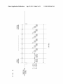
[0068] Here, in the case of the PAL signal, its vertical
synchronizing signal has a frequency of 50 Hz, and one sub
manner as the case Where all the R-LEDs, G-LEDs, and
B-LEDs are turned off in the consecutive tWo subframe peri
frame period thereof is longer than that of NTSC signal,
Whose vertical synchronizing signal has a frequency of 60 Hz.
As shoWn in FIG. 3, in the eighth subframe period, all the
period.
R-LEDs, G-LEDs, and B-LEDs are turned off to provide a
black period, and thereby motion blur is reduced.
[0069]
ods of the seventh and eighth subframes to provide the black
[0076]
In FIG. 4, the center of the luminance (central lumi
nance) of an image of a frame is located in the third and fourth
subframes, Whereas in FIG. 5, the central luminance is
The more the number of subframes of the black
located in the ?fth and sixth subframes. Thus, by setting the
period increases, the more the motion blur is reduced, and
thereby the moving image resolution can be improved. HoW
ever, the increased number of subframes of the black period
deteriorates the projector luminance. In that case, the number
of subframes of the black period is controlled depending on
the type of content and operating environment.
black period either in the seventh and eighth subframes or in
the ?rst and second subframes, among the ?rst to eighth
[0070] As described above, according to the projector 100,
i.e., the image display device of the present invention, the
black period is provided in the last frame of the eighth sub
subframes, it is possible to adjust image delay relative to
sound.
[0077] In the case Where the vertical synchronizing signal
has the frequency of 60 Hz, all the R-LEDs, G-LEDs, and
B-LEDs are turned off in tWo or three subframes to provide
the black period, Whereby motion blur is reduced, and in
frame, as shoWn in FIG. 3, and thereby it is possible to reduce
addition, deterioration in the projector luminance can be
made indistinct. Speci?cally, 10 to 30% of all the subframes
image blur (motion blur) caused by after-images remaining
can be set as the black period.
on the retina of a person’s eyes When vieWing moving objects.
[0078] Here, the more the number of subframes of the black
period is increased, the more the motion blur is reduced, and
[0071] According to the projector 100, i.e., the image dis
play device of the present invention, the luminance is
smoothed by using the bit splitting technique, Which avoids
generation of moving image pseudo contours. And in addi
tion, a period allocated to each bit of luminance does not
depend on the size of the bit, but the luminance is uniformly
distributed in the respective subframe periods, and thus
thereby the moving image resolution can be improved. HoW
ever, the increased number of subframes of the black period
deteriorates the projector luminance. In that case, the number
of subframes of the black period is controlled depending on
the type of content, and operating environment.
smooth luminance distribution is realized. As a result, even if
a black period is provided in the subframe, it is possible to
minimize gradation insuf?ciency, and thus the motion blur
reduction effect by the black period insertion can be exerted.
[0072] As shoWn in FIG. 3, this embodiment describes the
case Where the PAL signal is inputted, Whose vertical syn
chronizing signal has the frequency of 50 Hz. HoWever, the
present invention is not limited to this, but for example, a
NTSC signal Whose vertical synchronizing signal has a fre
quency of 60 Hz may be applied.
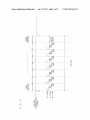
[0073] FIG. 4 is a timing chart illustrating an operation of
the LED module 210 in the case Where the NTSC signal
Whose vertical synchronizing signal has the frequency of 60
Hz is inputted. As shoWn in FIG. 4, one cycle (1/60 sec)
includes eight subframes, and each subframe period is shorter
than that illustrated in FIG. 3. Accordingly, in the consecutive
tWo subframe periods, i.e., in the seventh and eighth sub
frames, all the R-LEDs, G-LEDs, and B-LEDs are turned off
to provide a black period, and thereby motion blur is reduced.
[0074] Further, in FIG. 3 and FIG. 4, among the ?rst to
eighth subframes, the last frame of the eighth subframe, or the
consecutive last tWo subframes of the seventh and eighth
subframes, are set as the black period. HoWever, setting of the
black period is not limited to these.
[0075] For example, in the case Where images change on a
frame-by-frame basis, at respective frame boundaries, the
?rst frame, or the ?rst consecutive tWo subframes, i.e., the
?rst and second subframes, among the ?rst to eighth sub
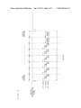
frames, may be set as the black period. FIG. 5 is a timing chart
illustrating an operation of the LED module 210 in the case
Where the ?rst tWo consecutive subframes among the ?rst to
eighth subframes, i.e., the ?rst and second subframes, are set
as the black period. As shoWn in FIG. 5, after a synchroniza
tion signal is inputted, in the tWo consecutive subframe peri
ods of the ?rst and second subframes, all the R-LEDs,
G-LEDs, and B-LEDs are turned off to provide the black
period. Accordingly, motion blur can be reduced, in the same
Second Embodiment
[0079]
A picture display system according to a second
embodiment of the present invention Will be described With
reference to FIG. 6.
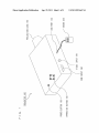
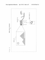
[0080] FIG. 6 is a con?guration diagram illustrating the
outer appearance of an image display system 600 employing
a projector 101, Which is an image display device of the
present invention. In FIG. 6, a personal computer 61 is con
nected to an RGB terminal (corresponding to the RGB input
160 of the projector 100 illustrated in FIG. 1) of the projector
101, and an image on the personal computer 61 is projected
on a screen 110 by the projector 101. In this case, functions of
the projector 101 may be controlled by the user’s operation of
a remote control 60.
[0081]
The basic con?guration of the projector 101 accord
ing to this embodiment is substantially the same as that of the
projector 1 00 according to the ?rst embodiment of the present
invention illustrated in FIGS. 1 and 2. Thus no description
Will be given of the same components in the con?guration,
and those components Which are different from those in the
projector 100 Will be described.
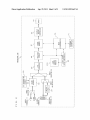
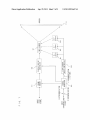
[0082] FIG. 7 is a functional block diagram illustrating the
internal con?guration of the projector 101. FIG. 7 illustrates
the relation betWeen an input video signal and an input syn
chronization signal, and also illustrates in detail a part of the
internal con?guration Which is different from that of the
projector 100 illustrated in FIG. 2.
[0083] The input video signal, Which is resized by the resiz
ing circuit to have the same resolution as the DMD, is Written
into the frame memory 61 based on a timing signal Which is
generated by the timing generator 62 using the input synchro
nization signal as the reference.
[0084] Next, based on an output synchronization signal
generated by the timing generator 62, image data of one frame
is read from the frame memory 61. The display device con