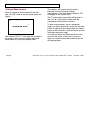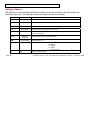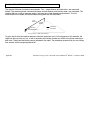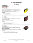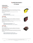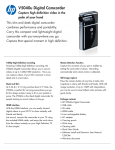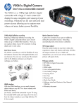
1
IMPULSE
IMPULSE LR
LIMITED WARRANTY
Laser Technology, Inc. (LTI) warrants the Impulse to be in good working order for a period of one year from the date
of purchase from LTI or an authorized LTI product dealer. Should the product fail to be in good working order at any
time during the warranty period, LTI will, at its option, repair or replace the product at no additional charge, except as
set forth below. Repair parts and replacement parts and products become the property of LTI. This limited warranty
does not include service or repair of damage to the product resulting from accident, disaster, misuse, abuse, or nonLTI modification of the product.
To activate your warranty, return the warranty card from the front of this manual to LTI within 30 days of purchase. To
obtain limited warranty service, deliver the product during the one-year period to the Laser Technology Service
Center and provide proof of the purchase date. If the product is delivered by mail, you agree to insure the product or
assume the risk of loss or damage in transit, and to prepay the shipping container or equivalent.
LTI hereby disclaims all other express and implied warranties for the product, including warranties of merchantability
and fitness for a particular purpose. (Some states do not allow the exclusion of implied warranties, so the above
limitation may not apply to you.)
Electronic Copy of LTI’s Impulse User’s Manual 8th Edition © October 1998
LIMITED WARRANTY
If the product is not in good working order as warranted above, your sole remedy shall be repair
or replacement as provided above. In no event will LTI be liable to you for any damages,
including any lost profits, lost savings, or other incidental or consequential damages arising from
the use or inability to use such product. Furthermore, LTI shall not be held responsible if any LTI
authorized dealer has been advised of the possibility of such damages, or for any claim by any
other party.
Note: The Warranty Validation Card (at the front of this manual) must be
completed and activated in order to benefit from this warranty. No
exceptions.
In the unlikely event that your new LTI laser should require warranty or repair service, call us to
receive a Return Merchandise Authorization (RMA) number before returning your product.
Contact us at:
Laser Technology
7070 South Tucson Way
Englewood, CO 80112 USA
Phone:
Fax:
Web Site:
303-649-1000
303-649-9710
www.lasertech.com
Electronic Copy of LTI’s Impulse User’s Manual 8th Edition © October 1998
Electronic Copy of LTI’s Impulse User’s Manual 8th Edition © October 1998
PRECAUTIONS
Avoid staring directly at the laser beam for prolonged periods of time.
The Impulse is designed to meet stringent F.D.A. eye safety requirements and is classified as eye-safe to Class 1
limits, which means that virtually no hazard is associated with directly viewing the laser output under normal
conditions. As with any laser device, however, it is recommended that you avoid staring into the transmit aperture for
prolonged periods while firing the laser.
Never attempt to view the sun through the scope.
Looking at sun through the scope may permanently damage your eyes.
Never point the instrument directly at the sun.
Exposing the lens system to direct sunlight, even for a brief
period, may permanently damage the laser transmitter.
Do not expose the instrument to extreme temperatures.
Impulse components are rated for a temperature range of -30° C (-22° F) to +60° C (+140° F). Do not expose the
instrument to temperatures outside of that range.
Electronic Copy of LTI’s Impulse User’s Manual 8th Edition © October 1998
FOREWORD
The Laser Technology, Inc. Impulse is a light-weight, hand-held laser ranging instrument that allows you to quickly
and conveniently measure distances, heights, and vertical angles. The Impulse uses sensors to measure distances
and vertical angles, and menu-driven software to convert sensor readings to meaningful measurements.
The Impulse can be held easily in one hand and features simple three-finger operation: you execute most primary
operations simply by sighting your target through the scope and briefly pressing one of three buttons conveniently
located at your fingertips.
This manual covers the options, characteristics, and operation of these Impulse models: Impulse 200, Impulse
200LR, Impulse 100, and Impulse 100LR. Your particular Impulse may not have all the options described.
The Impulse 100 and 100LR take
these measurements:
The Impulse 200 and 200LR take
these measurements:
- Slope Distance
- Cumulative and Difference Distance
- Slope Distance
- Horizontal distance
- Vertical Distance
- Height
- Inclination
- Cumulative and difference distance
The LR (“long range”) models function identically to a standard Impulse, but provide
longer ranging capability to non-cooperative targets.
Electronic Copy of LTI’s Impulse User’s Manual 8th Edition © October 1998
TABLE OF CONTENTS
GETTING STARTED QUICKLY ................ 1
BASIC IMPULSE PACKAGE ................................. 1
ACCESSORIES..................................................... 1
INSERTING THE BATTERIES ............................... 2
POWERING ON AND OFF .................................... 3
TAKING A MEASUREMENT ................................ 4
THE ANATOMY OF THE IMPULSE ......... 6
SENSORS ............................................................ 6
SIGHTING SCOPE ................................................ 7
FRONT AND BACK PANELS ................................ 7
INSTRUMENT OPTIONS AND
INDICATORS ................................................. 8
MEASUREMENT MODES .................................... 9
MEASUREMENT MODIFIERS ............................ 10
INDICATORS / WARNINGS ................................ 11
SETTINGS / OPTIONS ........................................ 12
ERROR CONDITIONS ........................................ 14
USING THE BUTTON PANELS ................ 15
SETTING UP FOR LEFT-HANDED
OPERATION................................................. 18
SWITCHING THE HAND STRAP ......................... 18
RECONFIGURING THE BUTTON PANELS .......... 19
TAKING A BASIC MEASUREMENT .......20
UNGROUPING SENSORS - IMPULSE 200............22
SETTING THE SCOPE DOT INTENSITY ...............23
SETTING THE MEASUREMENT UNITS ...............23
PERCENT SLOPE ...............................................24
RANGE RESOLUTION ........................................24
POWER CONSERVATION INTERVALS ................24
TURNING THE BEEPER ON AND OFF.................26
TAKING A HEIGHT MEASUREMENT ...27
HEIGHT PIVOT OFFSET .....................................30
ADDITIONAL NOTES .........................................32
Calculating a Pivot Offset ...........................33
TAKING A MULTIPLE
MEASUREMENT..........................................34
DIFFERENCE MEASUREMENTS .........................34
CUMULATIVE MEASUREMENTS .......................36
TARGETING .................................................39
LISTENING TO THE INSTRUMENT......................40
AIMING POINT ..................................................41
SETTING THE RANGE OFFSET ...........................42
SETTING A GATE WINDOW ..............................43
Turning On the Gates ..................................44
Electronic Copy of LTI’s Impulse User’s Manual 8th Edition © October 1998
TABLE OF CONTENTS
Setting a Short Gate Value.......................... 45
Setting a Long Gate Value .......................... 45
Clearing Gate Values.................................. 45
USING THE FILTER OPTION .............................. 46
NOTES ON MEASUREMENT MODIFIERS ........... 47
THE EDIT MODE ........................................ 49
DOWNLOADING DATA............................. 51
DOWNLOADING ............................................... 51
THE DNLD OPTION ......................................... 52
DISCARDING ERROR MESSAGES ...................... 54
OPTIONAL REMOTE TRIGGER .......................... 54
SERIAL INTERFACE SPECIFICATIONS ............... 55
IMPULSE (IP200 OR IP100) FORMAT ............... 55
Queries........................................................ 55
Download Messages ................................... 56
CR400 FORMAT............................................... 57
NMEA Compliance ..................................... 57
Queries........................................................ 58
Download Messages ................................... 59
SPECIFIC MESSAGE FORMATS ......................... 60
Version ID................................................... 61
Basic Measurement & Horizontal Vector ... 62
Range Difference .........................................64
Range Cumulative........................................65
Height ..........................................................66
USING A TRIPOD OR MONOPOD ...........67
YOKE ................................................................67
YOKE MOUNT ..................................................68
COMPASS MOUNT ............................................70
COMPASS ..........................................................70
NOTE FOR CRITERION USERS ...........................71
CARE AND MAINTENANCE .....................72
OPERATING TEMPERATURE .............................72
MOISTURE AND DUST PROTECTION .................72
SHOCK PROTECTION.........................................72
CLEANING AND STORAGE ................................72
CARING FOR THE SCOPE ...................................73
CHECKING THE DISPLAY SCREEN ....................73
CHECKING THE BATTERIES ..............................74
REALIGNING THE SCOPE ..................................74
ALIGNING THE TILT SENSOR - IMPULSE 200....76
SPECIFICATIONS........................................80
Electronic Copy of LTI’s Impulse User’s Manual 8th Edition © October 1998
GETTING STARTED QUICKLY
When you receive your Impulse laser instrument,
check to see that you have received everything you
ordered and that it all arrived undamaged.
Basic Impulse Package
•
•
•
•
•
•
Impulse laser instrument
Belt clip
Hand strap
Two AA batteries
User’s manual
Padded carrying case
Page 1
Accessories
In addition, you may have ordered one or more of
these optional accessories:
•
•
•
•
•
Tripod yoke and mount
Compass and mount
Monopod
Two Impulse download cables:
- Turck 4-pin to DB 9-pin cable
- Turck 4-pin to HP 200/48 10-pin cable
Data collector and software
Electronic Copy of LTI’s Impulse User’s Manual 8th Edition © October 1998
GETTING STARTED QUICKLY
Inserting the Batteries
Load the batteries by inserting them positive-endfirst into the battery compartment on the Impulse’s
back panel.
Twist the battery compartment cap
clockwise, finger tight, to secure it.
Warning: Do not use the new style of AA
batteries with the “voltage check” feature built
into the cell.
Page 2
The “voltage check” cells are slightly larger in
diameter and will cause problems when inserting
into and extracting from the battery compartment.
The diameter of the battery tube on your Impulse
was chosen carefully to allow easy in/out of normal
AA batteries with no excess room for cell shifting
and possible loss of contact. Note that voltage
check batteries will cause similar problems with
most standard metal tube AA flashlights. Laser
Technology will not be responsible for damage to
the unit as a result of trying to force these new style
cells in or out of the battery tube. Do not peel off
the voltage check wrapper; this can cause an
instrument short circuit.
In addition, the instrument has its own battery
voltage monitor, thus eliminating the need for
voltage check cells.
Electronic Copy of LTI’s Impulse User’s Manual 8th Edition © October 1998
GETTING STARTED QUICKLY
Powering On and Off
The Impulse has a row of three buttons on either
side of the instrument. Later you will learn the full
use of the button panels, including setting them up
for left-handed use. For a quick start at the
instrument, however, power on and off by using the
buttons depicted in the illustrations at the right.
Press this button
to power on
Rear of instrument
Power on by pressing the rear-most button (the
button closest to you) on either button panel. Power
off by simultaneously pressing the two forwardmost buttons on the left panel. (The instrument may
also power itself off after a period of inactivity.)
Press these two buttons
simultaneously to power off
Press this button
to power on
Rear of instrument
Page 3
Electronic Copy of LTI’s Impulse User’s Manual 8th Edition © October 1998
GETTING STARTED QUICKLY
Taking a Measurement
When you power on the instrument for the first
time, the LCD screen on the rear panel shows this
display:
RIGHT
The “F” means the measurement will be taken in
feet. (An “M” in this location would mean the
measurement will be taken in meters.)
HD
To take a measurement, aim to a convenient
target—an interior wall will do—press the rear-most
button on right panel (the same button you used to
power on the instrument), and hold it down until the
instrument acquires a target.
F
The indicator “RIGHT,” in the upper left quadrant of
the screen, means you are using the right-hand
button panel as your primary control panel.
Page 4
The indicator “HD” means the instrument is
prepared to take a horizontal distance
measurement. (The slope distance indicator “SD”
will appear on the Impulse 100.)
You might not notice any difference the first time
you press the button; in that case, just press it
again. As a power conservation measure, the red
dot sighting scope
Electronic Copy of LTI’s Impulse User’s Manual 8th Edition © October 1998
GETTING STARTED QUICKLY
automatically turns its red dot off if a measurement
has not been taken within a predetermined time
limit. The first press will turn on the red dot, the
second press will take the measurement. You may
have a fixed-crosshair scope on your Impulse, in
which case two button presses are not needed to
take a measurement.
After a brief delay, the instrument emits a highpitched beep and displays something like this:
RIGHT
HD
F
The large number in the center of the display is the
distance to the target.
“DNLD” (in the lower right quadrant) means the
number is available at the serial port. If you have a
connection to a data logger or notebook computer,
you could download the number to be stored and
saved.
If you like, feel free to try some more button
presses and take more measurements. The
important thing for the moment is that you have
experienced the Impulse’s basic point-and-shoot
operation, and you have a feel for how the
instrument uses indicators on the screen to let you
know what operations are available to you at any
given time.
DNLD
Page 5
Electronic Copy of LTI’s Impulse User’s Manual 8th Edition © October 1998
THE ANATOMY OF THE IMPULSE
Sighting scope
Transmit lens
Receive lens
The Impulse consists of a laser range sensor, a
fluid tilt sensor (Impulse 200 only), a sighting
scope, and a data output port. The sensors are
integrated with software controls and accessed
through the two 3-button panels on either side of
the unit and a liquid crystal display (LCD) screen on
the rear panel.
Sensors
Front View
Speaker
Button panel
Button panel
The Impulse laser range sensor provides
immediate access to slope distance values. The
Impulse determines distance by measuring the time
of flight of short pulses of infrared light. The
Impulse has a broad spectrum of sensitivity and
can work with both reflective and nonreflective
targets.
LCD screen
Battery
compartment
Serial port
connector
The maximum measurement distance, about 575
meters (1880 feet), varies with target and
environmental conditions.
Rear View
Page 6
Electronic Copy of LTI’s Impulse User’s Manual 8th Edition © October 1998
THE ANATOMY OF THE IMPULSE
In the Impulse 200, the tilt sensor measures vertical
angles, which the Impulse uses to calculate height
and elevation and to determine slope-reduced
horizontal distances. The tilt sensor is capable of
taking full 360 degree angular measurements,
which is displayed by the tilt sensor as ±180
degrees. The instrument held level is at 0 degrees,
and is rotated up through +180 degrees, and down
through -180 degrees.
Sighting Scope
The sighting scope mounted atop the Impulse will
vary depending upon which option you chose.
The single-power sighting scope features an inscope, red aiming dot to help you aim accurately to
the target. You can vary the intensity of the dot to
account for different
Page 7
lighting conditions. See “Setting the Scope Dot
Intensity” under Taking a Basic Measurement.
The variable-power sighting scope features an inscope crosshair, and allows you to adjust the
magnification of the scope.
Front and Back Panels
The Impulse has two lenses on the front panel. The
top lens transmits infrared laser signals. The
bottom lens receives signals back from the target
and feeds signal information to the instrument’s
internal circuitry.
The back panel contains an LCD display screen,
battery compartment access, and a serial port
connector that allows you to connect the instrument
to a data collector or notebook computer.
Electronic Copy of LTI’s Impulse User’s Manual 8th Edition © October 1998
INSTRUMENT OPTIONS AND INDICATORS
The internal software of the Impulse is organized into options. Each option represents a specific Impulse
measurement or setup function and has a corresponding indicator on the LCD screen. To view all of the
possible Impulse indicators at once, power up the instrument by pressing the Fire or Fire2 button, and keep
the button pressed down. This is also a good way for you to check if all the components on your display are
working properly. The display will look like this:
RIGHT
LEFT
HT
SD
GATE
G S L
HD
VD
MULTI
CUM
SYS
DIFF
INC
F M
D G
% V
LASER
BATT
OFFSET
PIVOT
BORE
UNITS
FILTER
UPDATE
CAL
MEM
DNLD
AUTO
The display indicators are grouped by function, and fall into four categories: measurement modes,
measurement modifiers, indicators/warnings, and settings/options. Note: Your instrument may not have all the
features described.
Page 8
Electronic Copy of LTI’s Impulse User’s Manual 8th Edition © October 1998
INSTRUMENT OPTIONS AND INDICATORS
Measurement Modes
Using a laser sensor and optional tilt sensor, the Impulse can take six different types of measurements:
Indicat
or
Explanation
HT
Height
HD
Horizontal Distance
VD
Vertical Distance
(Impulse 200 only) Measures the distance between a target object and
the perpendicular to the path of the horizontal distance
SD
Slope Distance
Measures the straight-line distance between the Impulse and a target
object
INC
Inclination
MULTI
Page 9
Function
Multiple
Measurements
(Impulse 200 only) Measures the height of an object
(Impulse 200 only) Measures the level distance between the Impulse
and the plane of the target object
(Impulse 200 only) Measures the angle of inclination between the
Impulse at level, and the target
Allows the Impulse to take more than one measurement in succession
CUM - maintains a cumulative distance measurement for a succession
of targets
DIFF - calculates the differences between a base distance and a
succession of targets
Electronic Copy of LTI’s Impulse User’s Manual 8th Edition © October 1998
INSTRUMENT OPTIONS AND INDICATORS
Measurement Modifiers
Measurement modifiers are options that can help you select or eliminate targets and help you take the most
accurate measurements possible. The measurement modifiers are:
Indicator
Function
Explanation
GATE
Measurement
Gate
Sets up a measurement “gate” or “window.” When gates are set, the
Impulse will only measure targets that are at or beyond the window’s
minimum distance, and at or within the window’s maximum distance
G - Gate option is on
S - Short gate is set, increasing the minimum measuring distance
L - Long gate is set, decreasing the maximum measuring distance
OFFSET
Range Offset
Adds or subtracts a distance from the slope distance measurement
PIVOT
Height Pivot
Offset
(Impulse 200 only) The difference between the measuring point of the
instrument and the point at which it pivots to take top and base angles
during hand-held height measurements
FILTER
Filter Mode
Reduces the sensitivity of the laser sensor to only detect light returned
from a reflector
Page 10
Electronic Copy of LTI’s Impulse User’s Manual 8th Edition © October 1998
INSTRUMENT OPTIONS AND INDICATORS
Indicators / Warnings
These indicators impart status, warnings, or hints. They are:
Indicator
LASER
Function
Laser
Explanation
The laser sensor is firing
BATT
Battery
(Flashing) Time to replace the batteries
DNLD
Download
Measurement is available for download
Down Arrow
Up Arrow
Page 11
(Flashing) (Impulse 200 only) Take base measurement in HT option or
first measurement in tilt calibration
(Flashing) (Impulse 200 only) Take top measurement in HT option or
second measurement in tilt calibration
Electronic Copy of LTI’s Impulse User’s Manual 8th Edition © October 1998
INSTRUMENT OPTIONS AND INDICATORS
Settings / Options
The Impulse has system settings and options that allow you to use the Impulse in the most efficient and
convenient way for you. The following list covers the options that are user-selected.
Indicator
Function
SYS
RIGHT/LEFT
BORE
System
Right or Left
Bore Sight
Explanation
Selects Impulse operating characteristics
Right or left button panel is primary
Aligns the red dot or crosshair in the sighting scope
CAL
Tilt Calibration
(Impulse 200 only) Calibrates the tilt sensor
UPDATE
Audio Update
(Red dot scope only) Beeper is on to indicate instrument activity and
measurement result
AUTO
Automatic
Download
LED Backlight
UNITS
V
Page 12
Units
Volts
Measurements downloaded automatically
LED backlight is on
Select measurement units
F - Feet
M - Meters
D - Degrees
G - Grads
% - Percent Slope
Battery voltage reading
Electronic Copy of LTI’s Impulse User’s Manual 8th Edition © October 1998
INSTRUMENT OPTIONS AND INDICATORS
Additional Note:
The middle portion of the screen, in addition to displaying measurements, is itself sometimes used as an
indicator of sorts; if dashed lines appear, the instrument is ready to take a measurement; if the middle of the
screen is blank, the option has suboptions that can be accessed by pressing Fire.
RIGHT
HD
RIGHT
SYS
F
HD has no subfunctions. The dashes show
where the measurement will display.
Page 13
The SYS option has subfunctions; use
the Fire button to enter the subprocedure.
Electronic Copy of LTI’s Impulse User’s Manual 8th Edition © October 1998
INSTRUMENT OPTIONS AND INDICATORS
Error Conditions
The middle area of the screen is also where error
codes are displayed. If the Impulse detects an error
in a measurement or download attempt, a lowpitched tone issues from the speaker and an error
code displays.
The most common error is that the Impulse simply
cannot find the target. Most other errors are
similarly trivial; correcting them requires only that
you reshoot the measurement you were trying to
take, or try the download again.
You can opt to have measurements with errors
discarded instead of downloaded when in the
automatic download mode. See “Discarding Error
Messages” in Downloading Data.
Page 14
Code
Explanation
doF Display overflow. The measurement exceeds the
display capacity, or measurement angle at ±90
degrees.
EoF Editor overflow.
E01 Failure to lock on target. Reposition instrument
and retake measurement.
E02 Target lost during measurement. Reposition and
retake measurement.
E03 Unstable aim. Steady the instrument and retake
the measurement.
E04 (Impulse 200 only) Invalid tilt sensor reading.
Contact Laser Technology if error persists.
E05 (Impulse 200 only) Tilt reading outside ±90 degree
limit on % slope or height measure-ment.
Reposition and retake measurement.
E06 (Impulse 200 only) Tilt calibration error. See the
Care and Maintenance section of this manual.
E52 Temperature too hot. Stop operation.
E53 Temperature too cold. Stop operation.
E60 Calibration or code memory checksum failure.
E61 Contact Laser Technology.
E62
Electronic Copy of LTI’s Impulse User’s Manual 8th Edition © October 1998
USING THE BUTTON PANELS
You control the Impulse through two 3-button
panels on either side of the instrument. One panel
is always designated the primary button panel; the
other, the secondary panel. You can tell which
panel is primary by the LEFT or RIGHT indicator
showing in the upper left quadrant of the backpanel display screen.
the primary Fire button; “Fire2” means the
secondary Fire button.
The two button panels are identically laid out. The
button nearest the rear panel is the “Fire” button.
The middle button is the “Forward” button. And the
button nearest the front panel is “Back.”
Button 3
(“Back”)
rear of instrument
(display side)
Button 1
(“Fire”)
Button 2
(“Forward”)
Left-side Button Panel
In the Impulse lexicon, buttons on the primary
control panel are referred to by the button name,
while buttons on the secondary panel are referred
to by the name suffixed with a ‘2.’ So “Fire” means
rear of instrument
(display side)
Button 1
(“Fire”)
Button 2
(“Forward”)
Button 3
(“Back”)
Right-side Button Panel
Page 15
Electronic Copy of LTI’s Impulse User’s Manual 8th Edition © October 1998
USING THE BUTTON PANELS
Because the Impulse features some fairly complex operations, but has a total of only six buttons to effect those
operations, the specific function assigned to a button differs with:
•
the operation,
•
whether the button is on the primary panel or secondary panel, and
•
how long you hold the button down. (A “short” press of a button simply means you press it and
release it immediately. A “long” press means you press the button and hold it down for about two
seconds.)
In general, Forward and Back move through menus, and Fire selects options, while the secondary buttons
control the scope aiming dot and the display backlight. Specifically, the buttons have the functions indicated in
the table on the next page.
Page 16
Electronic Copy of LTI’s Impulse User’s Manual 8th Edition © October 1998
USING THE BUTTON PANELS
Button
Fire
Fire2
Forward
Forward2
Back
Back2
Page 17
-
Function
Powers on the instrument.
For options with submenus (HT, GATE, MULTI, SYS), selects the option.
For measurement options (SD, HD, VD, INC), initiates a measurement by firing the laser. With red dot
sighting scope: the first press turns on the red dot if it is off, the second press fires the laser.
In system setup functions, selects or toggles values.
In edit mode, accepts a manually entered value.
No function in measurement operations.
In system setup functions, invokes optional “edit mode” so a value can be entered or altered.
Once in edit mode, advances to the next digit.
Moves “forward” in the options in a menu.
When DNLD is showing, sends a download message out the serial port.
In edit mode, first press restores the edit value, second press abandons the edit.
Long press: sends a download message out the serial port.
With red dot sighting scope, varies the intensity of the scope dot.
When pressed simultaneously with Back2, turns off the power.
In edit mode, increments the digit value.
Moves “backward” in the menu (selects the previous option or “backs out” of a submenu).
Clears DNLD indicator.
In edit mode, first press restores the edit value, second press abandons the edit.
Long press: clears out the current measurement value.
Turns the screen backlight on/off.
In edit mode, decrements the digit value.
When pressed simultaneously with Forward2, turns off the power.
Electronic Copy of LTI’s Impulse User’s Manual 8th Edition © October 1998
SETTING UP FOR LEFT-HANDED OPERATION
The Impulse can be operated with equal ease by
both right-handed and left-handed operators. The
instrument comes configured for right-hand users
but can be easily reconfigured by doing two things:
•
Switching the hand strap to the left side of the
instrument.
•
Reconfiguring the button panels.
Switching the Hand Strap
To switch the hand strap, remove the screws that
attach the strap to the mounting plates. Use the left
thumb block and position the strap on the left side
of the instrument so the free end of the adjusting
strap is facing the rear of the instrument, and the
holes in the strap base align with the holes in the
mounting plates. Then simply reattach the screws.
PART#
1
2
3
4
5
6
7
Page 18
PART NAME
S c re w , M 4 x 8
T h u m b B lo c k , L e ft
H a n d S tra p
S c re w , M 3 x 1 0
F la t W a s h e r
T ri- R in g
S h o u ld e r W a s h e r
Q U A N T IT Y
1
1
1
1
1
1
1
Electronic Copy of LTI’s Impulse User’s Manual 8th Edition © October 1998
SETTING UP FOR LEFT-HANDED OPERATION
Reconfiguring the Button Panels
The Impulse has a three-button control panel on
each side of the instrument. One of those panels is
designated the primary panel; the other, the
secondary panel. The primary panel (denoted by
“RIGHT” or LEFT” in the upper left corner of the
display) controls the primary functions of the
instrument. The secondary panel controls ancillary
functions and generally gets much less use. For
easy handling, you will usually want the primary
panel to be the one on the same side as the hand
strap.
Follow this procedure to switch the primary panel:
1. Press the Fire button to power on the
instrument.
Page 19
2. Repeatedly press Forward or Back until the
indicator SYS shows in the upper right quadrant
of the back panel display screen.
3. Press Fire to enter the SYS submenu.
4. Repeatedly press Forward until SEL shows in
the middle of the display screen, and the panel
indicator begins flashing in the upper left
quadrant. (This is the last item in the SYS
submenu.)
5. Press Fire to toggle the primary panel between
RIGHT and LEFT.
6. With the desired panel indicator showing, press
Forward to accept the change. At this point, the
button panels have been switched and you will
need to press Back on the new primary panel to
back out to the main menu.
Electronic Copy of LTI’s Impulse User’s Manual 8th Edition © October 1998
TAKING A BASIC MEASUREMENT
The Impulse 200 takes five basic measurements. Two —slope distance and inclination—are measured
directly. The remaining three—horizontal distance, vertical distance, and percent slope—are calculated. The
Impulse 100 has no way to measure angles, and takes only slope distance measurements. The five
measurements are related; the relationships among them are illustrated here:
slope
distance
vertical
distance
Measured
inclination
Calculated
horizontal distance
"Percent slope" is 100 * tan(inclination)
To get a feel for how the Impulse operates, choose a target near you. For the purposes of this exercise, the
target can be as prosaic as, say, a wall at the end of the corridor outside your office or the fence around your
back yard. Then make the button presses indicated in the table. The procedure assumes that you are starting
from scratch, with the Impulse powered off.
Page 20
Electronic Copy of LTI’s Impulse User’s Manual 8th Edition © October 1998
TAKING A BASIC MEASUREMENT
Do this...
Press Fire. (The
HD indicator
shows on an
Impulse 200; the
SD indicator
shows on an
Impulse 100.)
You have just taken an HD (horizontal distance)
measurement to your fence, or whatever target you
chose. Each of the basic measurements operates
in essentially the same simple way—power on, aim,
and fire—except that you sometimes have a couple
of other considerations.
...to get this result:
RIGHT
HD
F
First, the screen must be displaying the indicator for
the measurement you want to take: HD for
horizontal distance, SD for slope distance, VD for
vertical distance, INC for inclination, etc. If the
correct indicator isn’t showing, press Forward until
it is.
Sight the target
through the scope
Press Fire, and
hold the Fire
button down until
the instrument
locks on a target,
then release
Page 21
RIGHT
HD
F
DNLD
Second, if you are using a red dot sighting scope,
the scope aiming dot may turn itself off after about
15 seconds of inactivity, as a power conservation
strategy. If the red dot isn’t showing, press Fire to
turn it back on. See Power Conservation Intervals,
later in this section.
Electronic Copy of LTI’s Impulse User’s Manual 8th Edition © October 1998
TAKING A BASIC MEASUREMENT
this section.) If after pressing Fire the red dot still
isn’t showing, you probably need to adjust the
intensity of the dot. See Setting the Scope Dot
Intensity, later in this section.
Ungrouping Sensors on the Impulse 200
The Impulse 200 takes only those readings
necessary to satisfy the current option. This makes
it possible to “ungroup” the sensors by taking a
separate reading with each sensor. Then by
scrolling to another option, the instrument will
combine those readings to calculate other related
measurements.
For example, when slope distance (SD) is
measured, only the range sensor is activated, and
when inclination (INC) is measured, only the tilt
sensor is activated.
Page 22
Now, a horizontal distance (HD) measurement is
calculated from SD, which is read by the range
sensor, and INC, which is read by the tilt sensor.
The straight-forward way of measuring HD is to
simply shoot when the HD indicator is showing, so
the instrument calculates everything at once.
But suppose, for example, that an obstruction or
other unusual situation prevents you from taking a
reliable reading with one or the other sensor. In that
case, you can shoot an SD measurement,
reposition the instrument slightly, and then take an
INC measurement. Then scroll to HD, and you will
see that the instrument has calculated a horizontal
distance from your two separate sensor readings.
Electronic Copy of LTI’s Impulse User’s Manual 8th Edition © October 1998
TAKING A BASIC MEASUREMENT
Setting the Scope Dot Intensity
The optional red dot sighting scope has six intensity
settings which vary from bright to off. Adjust the red
dot brightness by pressing the Forward2 button
repeatedly until the desired intensity is achieved.
Setting the Measurement Units
The Impulse will express measurements either in
English units or in metric units. You select the units
by accessing the SYS option. Here is the
procedure:
1. Use Forward and Back as needed to display
the SYS indicator.
2. Press Fire to select the SYS option.
3. Press Forward repeatedly until the UNITS
indicator at the bottom center of the display
screen begins flashing, and SEL shows in the
numeric display area.
Page 23
4. Press Fire to toggle between the F (feet) and M
(meters) indicators.
5. Press Forward to select F or M. The D
(degrees) or G (gradient) indicator begins
flashing.
6. Next, press Fire to toggle between D and G.
7. Press Forward to select D or G. The % indicator
flashes, and OFF shows in the numeric display.
8. If you wish to turn on Percent Slope, press Fire.
9. Press Back twice to accept the new settings
and back out to the main display.
Note: Changing your range measurement units will
affect several values you may have stored in
memory. The height pivot offset, range offset, and
gate values will be
Electronic Copy of LTI’s Impulse User’s Manual 8th Edition © October 1998
TAKING A BASIC MEASUREMENT
reset to zero. Basic and height measurements are
cleared, and only a cumulative distance total will be
converted from the current measurement units to
the newly selected units.
Percent Slope
Percent slope (indicated by “%”) is a calculation
equal to 100 times the tangent of the inclination
angle. It is a variant way of expressing the
inclination and is available on the Impulse 200 only.
An inclination angle of 5 degrees, for example, is
equal to a slope of about 8.75 percent. An
inclination of 90 degrees will generate the display
overflow error “doF,” and inclinations that exceed
±90 degrees will generate error “E05.”
If you have turned % on in the SYS-UNITS
Page 24
option, and an inclination measurement is
displayed, that measurement is a percent slope, not
an inclination angle. The % indicator shows to
remind you. (Note, however, that you can get
percent slopes only in the basic measurement
displays, never in the Height measurement
displays. Note also that the instrument never
downloads a percent slope. It always downloads
the inclination angle. The D/G indicator indicates
the units to be used in the download message.)
Range Resolution
A range value may have 1 or 2 decimal places
depending on how many will fit in the six digit
display. Most measurements will be resolved to two
decimal places, but values larger than 9999.99 and
smaller than -999.99 will only show one decimal
place.
Electronic Copy of LTI’s Impulse User’s Manual 8th Edition © October 1998
TAKING A BASIC MEASUREMENT
Power Conservation Intervals
To help conserve its batteries, the Impulse
incorporates two timed power-off intervals, one for
the scope aiming dot and one for the instrument as
a whole. (The red dot interval does not affect a
fixed-crosshair scope.) By default, if there is no
instrument activity for 15 seconds, the scope
aiming dot turns off. If there is no activity for two
minutes, the instrument turns off completely.
You can change the intervals to make them more
convenient for your measurement conditions. Here
is the procedure:
1. Press Forward/Back as necessary to show the
SYS option.
2. Press Fire to select the SYS option.
3. Press Forward repeatedly until the M
and V indicators begin flashing at the right
center of the screen. The numeric display area
will be showing the current interval settings, like
this:
RIGHT
M
V
The P notation indicates the power-off interval in
minutes; the d shows the scope-dot interval in
seconds.
4. Press Fire repeatedly until the numeric display
shows the intervals you want. Your choices are
these:
P2 d15 power off interval = 2 minutes
P5 d15
P5 d60
Page 25
SYS
scope dot interval = 15 seconds
power off interval = 5 minutes
scope dot interval = 15 seconds
power off interval = 5 minutes
scope dot interval = 60 seconds
Electronic Copy of LTI’s Impulse User’s Manual 8th Edition © October 1998
TAKING A BASIC MEASUREMENT
ALL On both intervals full on (the instrument
will not power down, and the scope
dot will never turn off). Care should
be taken in this mode, as it is highly
power consumptive.
5. Press Back twice to accept the new settings
and return to the main display.
Note: If you have turned the beeper off, the scope
aiming dot turns off after every measurement, even
in ALL On mode.
If the instrument powers down while you are using
it, all measurements will be lost except for
cumulative distance.
Turning the Beeper On and Off
Although the Impulse gives helpful audio updates
that tell what the instrument is doing, you may want
to turn the beeper off and use the instrument
silently. This feature is available for instruments
with red dot
Page 26
scopes only. To turn the beeper on or off:
1. Use Forward and Back as needed to display
the SYS indicator.
2. Press Fire to select the SYS option.
3. Press Forward repeatedly until UPDATE
flashes at the bottom of the screen.
4. Press Fire to toggle the beeper on or off. When
you turn if off, the flashes three times and
reads “OFF.” When you turn it on, the
instrument beeps three times and reads “On.”
5. Press Back twice to accept the new setting and
back out to the main display.
If the beeper is off, the scope aiming dot
automatically turns itself off after each
measurement. Press Fire to turn it back on to
prepare for a new measurement.
This setting will be saved upon power down.
Electronic Copy of LTI’s Impulse User’s Manual 8th Edition © October 1998
TAKING A HEIGHT MEASUREMENT
Measuring a height presents a simple geometric
problem easily within the capabilities of the Impulse
200: solve the triangle formed by the object, the
ground, and the instrument.
B
The Impulse implements the process with the HT
option. The option works by requiring that the
measurements be taken in a specific order. The
procedure is in the table on the next page; it begins
by assuming the Impulse is powered off.
You will notice, by the way, that an option is often
presented in the procedure surrounded by a
nimbus, like this:
HD
A
D
C
Height measurement: The instrument first
calculates AD, then measures angles CAD and
DAB. It then calculates BD and DC. The height is
the sum of BD and DC.
Page 27
That simply indicates that, on the screen, the option
will be flashing on and off. A flashing indicator
shows you the measure-ment you need to take
next; the indicator for the number being displayed
also shows on the screen, but does not blink.
Electronic Copy of LTI’s Impulse User’s Manual 8th Edition © October 1998
TAKING A HEIGHT MEASUREMENT
Button/Action
Press Fire to
turn on the
instrument
Press Back to
reach the Height
indicator
Result (example)
RIGHT
HD
_ _ _ _ _ _
RIGHT
Button/Action
F
Sight the target
through the
scope
Press Fire to
take the
horizontal
distance
measurement
HT
Result (example)
RIGHT
HT
HD
INC
F
DNLD
Press Fire to
advance into
the height
subprocedure
Page 28
RIGHT
HT
HD
_ _ _ _ _ _
F
Aim to the base
of the object
(even if you
can’t sight it),
and press Fire
to take the base
inclination
reading
RIGHT
HT
INC
D
DNLD
Electronic Copy of LTI’s Impulse User’s Manual 8th Edition © October 1998
TAKING A HEIGHT MEASUREMENT
Button/Action
Aim to the top of
the object (even
if you can’t sight
it), and press
Fire to take the
top inclination
reading
Press Fire to
display the
height of the
object
another target. At this point, you have several
options:
Result (example)
RIGHT
INC
HT
•
Pressing Forward downloads the height
measurement you just took.
•
Pressing Fire takes the horizontal distance
measurement for another HT procedure.
•
Pressing Back backs up so you can retake one
or more measurements. Note that the indicators
do not blink in this instance. Any measurement
you retake affects the final height calculation.
D
DNLD
RIGHT
HT
HD
F
DNLD
To clear the HD measurement, long-press Back.
Multiple short presses back you out to the main
display level (which also clears the measurement).
When the procedure completes, the height
calculation is showing in the middle of the screen,
and the HD indicator is blinking, signifying that the
instrument is prepared to take a horizontal distance
measurement of
Page 29
Electronic Copy of LTI’s Impulse User’s Manual 8th Edition © October 1998
TAKING A HEIGHT MEASUREMENT
Height Measurement Hints: The Impulse uses an
HD and the two successive INC readings to
calculate a height. Therefore, when taking a base
or top angle reading, you don’t need an actual
target to shoot to since only the tilt sensor is
activated. In the case of measuring a tree height,
you should aim to where you think the top of the
tree actually is, not just the highest point you can
see.
The best heights for tapered objects (such as trees)
or non-vertical objects are taken by placing a
reflector directly next to the target, at the center of
its girth. This insures the most accurate horizontal
distance reading, thus leading to the most accurate
height calculation. Filter mode is helpful in this
situation.
Page 30
To acquire multiple height points on a single tree
(or other object) whose height you have just
measured, press Back once, reshoot the top angle,
then press Fire to display the new height.
Height Pivot Offset
For the most accurate possible height
measurements, you should account for the
difference between the measuring point of the
instrument and the point at which it pivots to take
the base and top angle measurements.
To take that difference into account, the Impulse
provides the PIVOT option, which allows you to
specify a height pivot offset. The offset is added to
the slope distance measurement, enabling the
instrument to
Electronic Copy of LTI’s Impulse User’s Manual 8th Edition © October 1998
TAKING A HEIGHT MEASUREMENT
calculate a horizontal distance of the highest
possible accuracy.
The measuring point of the Impulse is at the center
point of the instrument. That point corresponds to
the yoke mounting point, so if you are using a tripod
or monopod, enter a pivot offset value of zero.
If you are using the instrument hand-held, the pivot
offset is of more concern. In this case, the offset
value depends upon how you hold the instrument
when you take a reading. For example, you might
hold it close to your face, or with your arm extended
out. If you hold it so the scope is against your eye
(without moving your head during a height
measurement), you will want to specify the back
panel as your pivot point. That means specifying a
pivot offset of 0.08 meters (0.25 feet).
Page 31
However, if you hold the instrument close to your
eye and tilt your head during a height reading, the
pivot point should be moved from the center of the
instrument to the back of your head.
Depending upon the precision necessary for your
height measurements, you can approximate your
pivot offset value, or use the formula at the end of
this chapter to calculate an exact pivot offset.
Here’s how to set a height pivot offset:
1. Use Forward/Back as necessary to show the
SYS option indicator.
2. Press Fire to select the SYS option.
3. Press Forward repeatedly until the PIVOT
indicator in the lower left corner of the display
window begins blinking, and HT is displayed in
the top left of the
Electronic Copy of LTI’s Impulse User’s Manual 8th Edition © October 1998
TAKING A HEIGHT MEASUREMENT
display window. At that point, the numeric
display shows the current pivot offset value with
the first digit blinking.
4. Edit in the pivot offset value in whole feet or
meters using the edit function. (See The Edit
Mode for more information.)
Note: The pivot offset cannot exceed 3 meters
(10 feet), and negative values will not be
accepted.
The pivot offset is now activated for all height
measurements, and is denoted by the PIVOT
indicator in the lower portion of the HT option
display screen.
Page 32
Additional Notes
Some additional notes on using the HT option and
the pivot offset:
•
The pivot offset is used only in height
measurements. It has no effect outside the HT
option.
•
When you are setting the pivot offset, you can
clear out the current value by long-pressing the
Back button.
•
If you change your mind and decide not to
change the offset value after all, short-press the
Back button twice to back out to the main
display.
•
A programmed range offset will not affect your
height calculation.
Electronic Copy of LTI’s Impulse User’s Manual 8th Edition © October 1998
TAKING A HEIGHT MEASUREMENT
Calculating a Pivot Offset
Before you can determine your pivot offset value,
you need to get comfortable with taking height
measurements and determine where you normally
hold the instrument, be it up near your face, or with
your arm extended out.
Next, pick an object whose exact height you
already know (called “Heightknown”), hold the
instrument in your usual manner as determined
above, and use the Impulse to measure the height.
As you are measuring the height, write down these
three values:
• the base inclination angle, in negative degrees
(called “θbase”)
• the top inclination angle, in positive degrees
(called “θtop”)
• the height that the instrument displays (called
“Heightlaser”)
Page 33
Now, use a scientific calculator to compute your
pivot offset:
Offsetpivot =
(Height known − Height laser )
(tan θ top − tan θ base )
where “tan” refers to the tangent of the
angle.
An accurate pivot offset is most critical for
measurements taken at shorter distances. For the
most accurate height measurements, mount the
Impulse on a yoke and use a tripod or monopod,
and set the pivot offset to zero.
Electronic Copy of LTI’s Impulse User’s Manual 8th Edition © October 1998
TAKING A MULTIPLE MEASUREMENT
The multiple measurement option (MULTI) allows
the Impulse to take measurements to a succession
of targets. What it does with those measurements
depends upon the MULTI suboption you are in at
the time:
Here’s how you take difference measurements:
•
DIFF (Difference) compares each measurement
to one set point and reports the difference.
2. Press Fire to enter the MULTI subprocedure.
The DIFF indicator displays.
•
CUM (Cumulative) accumulates the
measurements and maintains a running total.
Difference Measurements
Difference measurements calculate the differences
between a succession of targets and a single set
point. You can use either horizontal distance
measurements or slope distance measurements
(Impulse 200 only).
Page 34
1. Press Forward/Back until the MULTI indicator
shows in the upper right quadrant of the display
screen.
3. Press Fire to enter the DIFF subprocedure.
Impulse 100: The next display is a series of
dashes, with two arrows flashing in the right
corner. The instrument is now ready to accept
the set point.
Electronic Copy of LTI’s Impulse User’s Manual 8th Edition © October 1998
TAKING A MULTIPLE MEASUREMENT
Impulse 200: SEL shows in the numeric
display area, and HD flashes just to the left of
MULTI.
At this point, you must select whether to take all
of the measurements as horizontal distances or
slope distances. Horizontal distance is already
selected, as shown by the flashing HD
indicator. To use HD measurements, then,
simply press Forward to move to the next
display.
To select SD measurements, press Fire to start
SD flashing. Then press Forward to move to the
next display.
The next display is a series of dashes, with two
arrows flashing in the right corner. The
instrument is now ready to accept the set point.
Page 35
4. To set the point by laser, aim to a suitable
target and press Fire. If the aiming dot is off on
the red dot scope, the first press turns it on, and
you must press Fire again to measure the
target.
To set the point manually, invoke the Impulse
edit mode. See The Edit Mode for more
information.
Note: An edited set point cannot exceed
±999.99 feet or meters, but a set point
measured by the laser can extend to the full
range of the instrument.
5. Press Forward. The numeric display area
shows dashes, and the arrows turn off.
Electronic Copy of LTI’s Impulse User’s Manual 8th Edition © October 1998
TAKING A MULTIPLE MEASUREMENT
6. Aim to a target and press Fire. Again, if the
aiming dot is off on the red dot scope, the first
press turns it on, and you must press Fire again
to fire the laser.
7. The numeric display area shows the distance
difference between the set point and the target
you just measured. To download the value,
press Forward.
8. Repeat step 6 for as many targets as you have.
When you are finished, press Back twice to
back out to the main display.
Exiting the difference measurement option will clear
the difference measurement in memory.
Cumulative Measurements
A cumulative measurement lets you move from one
target point to another, stopping at each one to
measure the distance to the next target point. The
instrument accumulates the measured distances in
SD in the Impulse 100, and both SD and HD in the
Impulse 200 to give you a running total.
Here’s how you take a CUM measurement:
1. Press Forward/Back until the MULTI indicator
shows in the upper right quadrant of the display
screen.
2. Press Fire to enter the MULTI subprocedure.
The DIFF indicator displays.
3. Press Forward to toggle to the CUM indicator.
Page 36
Electronic Copy of LTI’s Impulse User’s Manual 8th Edition © October 1998
TAKING A MULTIPLE MEASUREMENT
4. Press Fire to enter the CUM subprocedure.
Impulse 100: The next display is a series of
dashes, with two arrows flashing in the right
corner. The instrument is now ready to take the
first measurement.
Impulse 200: SEL shows in the numeric
display area, and HD flashes just to the left of
MULTI.
press Forward to move to the next display.
To select SD measurements, press Fire to start
SD flashing. Then press Forward to move to the
next display.
The next display is a series of dashes, with two
arrows flashing in the right corner. The
instrument is now ready to take the first
measurement.
At this point, you can select whether to take all
of the measurements as horizontal distances or
slope distances. You can toggle between the
two at any time.
5. Aim to a target and press Fire. If the aiming dot
is off on the red dot scope, the first press turns
it on, and you must press Fire again to fire the
laser.
Horizontal distance is already selected, as
shown by the flashing HD indicator. To use HD
measurements, then, simply
6. At this point, you have two options.
Page 37
If you are dissatisfied with the measurement for
some reason, repeat step 5 to retake the
measurement.
Electronic Copy of LTI’s Impulse User’s Manual 8th Edition © October 1998
TAKING A MULTIPLE MEASUREMENT
If you are satisfied with the measurement, and
wish to add it to your total, press Forward. The
instrument adds the current measurement to
the total and displays the new total.
7. When the total is showing, you have another
two options.
To simply take the next measurement without
downloading, return to step 5.
To download the current total, press Forward.
The arrows begin flashing again, and you may
then return to step 5 for the next measurement.
In most cumulative distance measurement
exercises, you will want to take a series of
measurements, and download only once, when
a series of related measurements are complete.
Page 38
Additional Notes:
The cumulative measurement total is saved in
memory even if the instrument is powered off. If
you turn the instrument on and scroll back to the
MULTI - CUM option, you can resume the
procedure with step 7.
To clear out the current total and begin another
series of measurements, long-press the Back
button while the cumulative distance total is
showing.
In the Impulse 200, the instrument keeps the total
in both SD and HD, and you can switch between
the two at any time. If you are viewing a single
distance measurement on the display, press Back
once and repeat step 4 to toggle between SD and
HD. If you are viewing a cumulative total, press
Back twice and repeat step 4.
Electronic Copy of LTI’s Impulse User’s Manual 8th Edition © October 1998
TARGETING
When selecting a target, keep in mind that most
surfaces can be measured directly. However, long
distances, multiple potential targets, or lack of an
actual physical object to shoot to may require
additional techniques. Here are some hints, which
are discussed in greater detail later in this section:
•
•
In the absence of a physical target, a simple
sheet of white paper suffices.
When shooting to near wooded or brushy
areas, use a multifaceted reflector and the
instrument’s filtering capability to filter out
unwanted targets. We recommend a 3-inch red
bicycle reflector such as a Cole model 03-3305,
which is available in hardware stores. Note:
This technique is not effective at
Page 39
•
•
•
•
long ranges due to the instrument’s reduced
sensitivity in filter mode.
Long ranges are most easily acquired using a
spectral or retroreflector.
Gating is helpful to isolate one target amongst
multiple potential targets. A measurement
window can be set up to reject targets outside
the range window.
The absolute minimum range of the Impulse is
essentially zero: in theory, you can measure
objects right up against the front panel. You can
increase the minimum range artificially by
setting the short measurement gate.
The absolute maximum range is about 575
meters (1880 feet). You can decrease the
maximum range artificially by setting the long
measurement gate.
Electronic Copy of LTI’s Impulse User’s Manual 8th Edition © October 1998
TARGETING
Listening to the Instrument
If the audio update feature is on, the Impulse will emit a variety of ticks and tones when it takes readings (see
“Turning the Beeper On and Off” under Taking a Basic Measurement). The sounds vary depending on what
the instrument is doing, and you can tell what is happening during a measurement simply by listening. The
table below explains the various sounds.
Sound
Growl
(extremely fast ticking)
Double
high-pitched tone
Single
high-pitched tone
Meaning
The instrument is trying to lock onto a target for a range measurement.
Nearly imperceptible when the instrument acquires the target immediately.
When the growling quits, the target is acquired and range readings are
being taken.
The instrument has completed the measurement, and all sensors acquired
readings.
The instrument has completed the measurement, but one or more of the
sensors failed to get a reading. The error message is indicated on the
display screen.
If you’re having trouble finding a target (you will know this by the growl you hear), you can hold the Fire button
down and pan the instrument around until it locates a target. The laser will try to acquire a target for up to 15
seconds, and if it is unsuccessful, it will time out and another trigger press will be needed to initiate a new
measurement.
When taking a measurement, be sure to keep the trigger pressed down and hold the instrument steady until
you hear the double-beep. Moving the instrument may cause inaccurate readings if the laser is shifted from
one target to another during a measurement.
Page 40
Electronic Copy of LTI’s Impulse User’s Manual 8th Edition © October 1998
TARGETING
Aiming Point
Under certain circumstances, you may want to
account for the displacement between the center of
the scope lens and the measuring point of the laser
instrument itself. The effect of the displacement is
most noticeable at short range—generally less than
150 meters (500 feet). At ranges of more than 300
meters (1000 feet), the displacement has no
practical effect.
aiming point
7 cm
2.75 in
You account for the displacement by aiming the
cross hairs 7 cm (2.75 inches) above the center of
the target. To ensure accurate aiming, modify a
target reflector as shown or purchase a commercial
lighted target with built-in offset aiming points.
Page 41
Electronic Copy of LTI’s Impulse User’s Manual 8th Edition © October 1998
TARGETING
Setting the Range Offset
The Impulse has a feature that allows you to alter
the measuring point of the instrument. You may
want to move it closer to your target, or further
away, depending upon your circumstances. For
these instances, the Impulse provides the OFFSET
option, which adds a distance to the slope distance
measurement. Since slope distance is used to
calculate horizontal distance and vertical distance
in an Impulse 200, the range offset will also affect
these options.
For example, if you want to measure the distance
between two walls, you would put the rear plate of
the Impulse up against one wall and measure the
distance to the other wall. Without a range offset,
the distance measured would be slightly shorter
than the
Page 42
actual distance, because the measuring point of the
instrument is at its center. Entering a range offset of
0.09 meters (.29 feet) would move the
measurement point back to the top of the battery
cap (which is against the wall) and would allow you
an accurate measurement from wall to wall.
Or, if the point you want to take a measurement
from is inconvenient to occupy, you could shoot the
distance to that point, then enter it as an offset that
will be figured into all subsequent measurements.
Range offsets up to ±999.99 may be entered. A
positive offset will lengthen your measurements, or
essentially move back your measurement point,
and a negative offset will shorten the measurement
by moving the measurement point closer to the
target.
Electronic Copy of LTI’s Impulse User’s Manual 8th Edition © October 1998
TARGETING
Here’s how to specify a range offset:
1. Use Forward/Back as necessary to show the
SYS option indicator.
2. Press Fire to select the SYS option.
3. Press Forward repeatedly until the OFFSET
indicator in the lower left portion of the display
begins blinking. At that point, the numeric
display shows the current range offset value
with the first digit blinking.
4. Edit in the range offset value in whole feet or
meters. Refer to The Edit Mode for more
information.
You will know that a range offset is “On” when you
see the OFFSET indicator in the lower left portion
of the display on SD, HD, and VD measurements.
Remember, the range offset is added onto the SD
Page 43
measurement, which is used to calculate
HD and VD.
Setting a Gate Window
Using the Gate option, it is possible to restrict the
Impulse to targeting objects within specified ranges.
The ranges specified, which are always slope
distance values, form the “gate window.” The range
minimum is called the “short gate;” the range
maximum, the “long gate.”
Short gate
Long gate
The Impulse will detect
only those targets inside
this gate window
Electronic Copy of LTI’s Impulse User’s Manual 8th Edition © October 1998
TARGETING
In essence, the gate window artificially extends the
instrument’s minimum range and restricts its
maximum range. One of the uses of the gate
window is to help you make certain you are getting
the right target when objects near you or just
beyond your intended target present a danger of
giving you false readings.
You needn’t set both gates. If you set only the short
gate, for example, the gate window extends from
the short gate value to the maximum range of the
instrument.
The gate window is restricted to a width of 1.5
meters (5 feet). If you set the gate window too
narrow, the instrument automatically adjusts it by
resetting either the short or long gate, taking the
most recent value entered as the standard to
recalculate the other by. So if the short gate
Page 44
is already set at 10 feet, for example, and then you
set the long gate to 12 feet, the instrument resets
the short gate to 7 feet.
A maximum value of 610 meters (2000 feet) for the
short gate, and 612 meters (2005 feet) for the long
gate may be entered.
You can set a gate by shooting to a target or by
editing in a value. The procedure:
Turning On the Gates
1. Use Forward/Back as necessary to show the
GATE indicator.
2. Press Fire to select the GATE option. The
numeric display area shows the current state of
the GATE option.
3. Press Fire to toggle GATE between On and
OFF. If the gates already have values assigned,
the S and L indicators
Electronic Copy of LTI’s Impulse User’s Manual 8th Edition © October 1998
TARGETING
will display (in addition to the G indicator).
4. To set gate values, press Forward. The S
indicator flashes and the short gate value
displays. Continue to the next step.
To back out to the main display, press Back. No
gate values have been set.
Setting a Short Gate Value
5. To set the gate by laser, aim to an appropriate
target and press Fire.
To set the gate manually, use the editing function.
Refer to The Edit Mode for more information.
6. To set a long gate value, press Forward. The L
indicator flashes, and the long
Page 45
gate value displays. Continue to the next step.
To back out to the main display, press Back.
The short gate is now set, and the S indicator is
displayed in distance measurement modes.
Setting a Long Gate Value
7. To set the gate by laser, aim to an appropriate
target and press Fire.
To set the gate manually, use the editing
function. Refer to The Edit Mode for more
information.
8. Press Back to back out to the main display. The
long gate is now set, and the L indicator is
displayed in distance measurement modes.
Electronic Copy of LTI’s Impulse User’s Manual 8th Edition © October 1998
TARGETING
Clearing Gate Values
If you want to clear out a gate value instead of
setting it, access the value as described above and
long-press Back or edit in zero.
2. Press Fire to select the SYS option. The
FILTER indicator begins to blink, and the
current state of the FILTER option is shown in
the middle of the screen.
Using the Filter Option
3. Press Fire to toggle FILTER between On and
OFF.
When you are working in an area that is crowded
with potential targets, you need to make certain the
instrument is detecting the right target. The best
way is to use a reflector as a target and to filter out
all others. To help accomplish that, the Impulse
offers a FILTER option to lock onto only highly
reflective targets.
Here’s how you turn FILTER on:
4. Press Back to save the desired setting and
back out to the main display. The FILTER
indicator displays in distance measurement
modes to show you when the option is on.
If you have FILTER turned on, always use a
reflector as a target because the instrument will
reject light returned from non-reflective targets.
1. Press Forward/Back as necessary to show the
SYS option.
Page 46
Electronic Copy of LTI’s Impulse User’s Manual 8th Edition © October 1998
TARGETING
Notes on Measurement Modifiers
•
Due to hardware constraints, gates work best
when the short gate value is 5 to 6 meters (15
to 20 feet) beyond the targets you wish to
reject.
•
Gates can be particularly useful when trying to
target an object through a window (or fog).
Measuring the distance to the window, then
setting the short gate 5 to 6 meters (15 to 20
feet) longer than that distance will ensure that
you are targeting the object beyond the window,
and not the window itself.
•
When the instrument is powered off (or turns
itself off), the gate option is reset to OFF, but
gate values are retained in memory. Offset and
filter settings are saved upon powering down.
Page 47
•
When using gates and offsets together, keep
the following in mind: Gates and offsets are
additive; a gate will reflect the same offset that
is applied to the target. Say, for example, that
you set the range offset to 15 meters and the
short gate to 30 meters. If you scroll back to
view the short gate value, it will then read 45
meters. But remember, the 45 meters is from
the virtual measuring point 15 meters behind
you. The gate is still 30 meters in front of you.
•
The range offset has the same additive effect
on the long gate setting.
•
A range offset does not affect ranges in HT
mode. And, although the range offset will not
alter the physical location of your gates, it will
alter the gate values seen on the display, so
you may want to
Electronic Copy of LTI’s Impulse User’s Manual 8th Edition © October 1998
TARGETING
clear the range offset to avoid confusion.
•
Gates are applied to SD measurements only,
and may not be exactly where expected in HD
or VD. See the diagram in the beginning of
Taking a Basic Measurement to clarify the
relationship between these measurements.
Page 48
Electronic Copy of LTI’s Impulse User’s Manual 8th Edition © October 1998
THE EDIT MODE
The Impulse has an editor which can be used to
manually enter numeric values for the range offset,
gate distances, the set point of difference distance
measurements, and in the Impulse 200, the height
pivot offset and tilt calibration offset.
•
The left-most digit will be flashing. Press
Forward2 or Back2 to toggle the first digit
between zero (which represents a positive
value) and the minus sign (-). Negative values
are not allowed for a height pivot offset.
The range offset, height pivot offset, and tilt
calibration offset are always input manually, and
entering these submenus automatically invokes the
editor.
•
Fire2 advances the edit to the next digit to the
right. Use Forward2 and Back2 to increment or
decrement the value of the digit. Repeat this
step as necessary to advance through each
digit in the entire distance value and edit each
digit individually.
When it is more desirable to manually input gate
distances and the set point of difference distance
measurements rather than shooting them in with
the laser, an optional editor is available by pressing
Fire2 when a distance measurement is requested
by the Impulse.
The distance value can be cleared to zero at any
time by long-pressing the Back key. Once altered
or cleared, the original distance value can be
restored by pressing either Forward or Back.
Once in the editor, follow this method:
Page 49
Electronic Copy of LTI’s Impulse User’s Manual 8th Edition © October 1998
THE EDIT MODE
When your edited value is correct, press Fire. A
beep will sound, and the value will be accepted in
memory and at this point can no longer be restored
by pressing Forward or Back. To exit the editor and
return to your submenu, press Forward or Back.
Note: If you exit out of the editor without
pressing Fire, your edit will not be saved!
Page 50
Electronic Copy of LTI’s Impulse User’s Manual 8th Edition © October 1998
DOWNLOADING DATA
The Impulse back panel contains a 4-pin serial
connector that allows you to download data to a
data collector or notebook computer. The
accessories needed for remote operations—cables
and a data collector—are available from LTI.
The data you wish to download must appear in the
display window for either instrument invoked or
requested data to be valid. If there are no
measurements available to download, the
instrument downloads null or zero values.
Current data collection software packages for the
laser include LTI Map, LTI Face Profiler, and
Traverse PC Handheld. Available interfaces for
GPS mapping systems include Ashtech Reliance,
Trimble Pathfinder, and CMT MC-GPS. Please call
us for more information on application software.
When a measurement is available, the DNLD
indicator displays. In that case, you can download
by query or manually by short-pressing Forward. A
successful download will be noted by a flashing
DNLD indicator, then it will disappear. Even if the
DNLD indicator is not showing, downloading is
always available by long-pressing the Forward
button.
Downloading
Measurement data can be downloaded using one
of three methods: manual download, automatic
download, or query.
Page 51
The automatic download mode, when activated,
downloads values automatically
Electronic Copy of LTI’s Impulse User’s Manual 8th Edition © October 1998
DOWNLOADING DATA
every time the instrument takes a measurement.
2. Press Fire to select the SYS option.
The download messages can take one of two
formats: the Impulse native format or, for those who
already have download software designed for the
Criterion family of instruments, the Criterion 400
format. The Impulse native format comes from LTI’s
Impulse series of instruments, and is denoted by
IP200 in the Impulse 200, and IP100 in the Impulse
100.
3. Press Forward repeatedly until the DNLD
indicator appears in the lower, right corner of
the display window, and On or OFF shows in
the numeric display area. The AUTO indicator
will also show, but will be blinking.
The DNLD Option
You set the automatic download mode, and change
the download format, with the SYS - DNLD option.
Here is the procedure:
1. Use Forward and Back as needed to display
the SYS indicator.
Page 52
4. Pressing Fire toggles between turning the auto
download feature ‘On’ and ‘OFF.’
5. Press Forward to select On or OFF. The AUTO
indicator disappears and the numeric display
area shows the download message format
setting (CR400, or IP200 or IP100).
6. Press Fire to toggle between CR400 and
IP200/IP100.
Electronic Copy of LTI’s Impulse User’s Manual 8th Edition © October 1998
DOWNLOADING DATA
Impulse 100: While CR400 is showing, you
have the option of pressing Fire2 to toggle the
range units (F or M) and angle indicator (D) on
and off. (Either F or M will be displayed,
depending upon which range units you have
selected.)
With F/M and D both off, all fields download as
null except for SD. Turning F/M on downloads
an SD value in the horizontal distance field, and
0.00 in the inclination field with a valid
measurement. Turning both F/M and D on will
download an SD value in the horizontal
distance field, and will download 0.00 in both
the inclination and azimuth fields. This is to
accommodate download software that does not
accept null values.
Page 53
Impulse 200: While CR400 is showing, you
have the option of pressing Fire2 to toggle the
D or G indicator on and off. (Either D or G will
be displayed, depending upon which units of
angular measurement you have selected.) With
D (or G) on, the azimuth field in the Criterion
horizontal vector message will download as
0.00; with D (or G) off, it downloads as null.
This is to accommodate download software that
does not accept null values for azimuth.
7. Press Back twice to back out to the main
display and save the DNLD settings.
The DNLD options are set and will come up the
next time you power on the instrument.
Electronic Copy of LTI’s Impulse User’s Manual 8th Edition © October 1998
DOWNLOADING DATA
Discarding Error Messages
When using the automatic download mode, you
can choose whether to download every
measurement, with or without null data from error
conditions, or to download valid measurements
only.
Set this preference by scrolling to the SYS-Err
option and press Fire to toggle the feature on, to
download both measurement values and null data,
or off, to download valid measurements only.
Optional Remote Trigger
It is possible to remotely trigger the Impulse and
take a measurement by using an external
computer, data collector, or switch closure. Remote
triggering is accomplished by providing an open
collector closure to ground or an active low TTL or
RS232 level
Page 54
signal to the ‘trigger’ pin on the serial connector.
This option requires a special order download cable
that connects the remote trigger signal from the
Impulse to the ‘RTS’ output signal of a computer’s
serial port.
When using a serial cable with a remote trigger
connection, care must be taken in controlling the
state of the RTS signal from the host computer.
Often times the default
state of the RTS signal will be low, causing
an inadvertent trigger of the Impulse. Since the
remote trigger signal is treated the same as a
keypress on the Impulse keypad, holding the signal
low is identical to holding down a function key,
which prevents a response to any additional keys
that are pressed.
Electronic Copy of LTI’s Impulse User’s Manual 8th Edition © October 1998
DOWNLOADING DATA
With the red dot sighting scope, if the red dot is off
when the remote trigger is activated, it is not
necessary to trigger twice to first turn on the dot
and then take a measurement. The remote trigger
will turn on the scope aiming dot and take a
measurement all at once.
Pin-out assignments for the Impulse serial port are:
Serial Interface Specifications
The Impulse serial interface uses RS-232 +/-12V
signal levels and data format. The format
parameters are set to:
4800 bps (CR400 format)
9600 bps (IP200 and IP100 format)
1 start bit
8 data bits
1 stop bit
no parity
Page 55
Impulse (IP200 or IP100) Format
Queries
The data you wish to download must appear in the
display window. If it does not, scroll to the
appropriate option. An Impulse format query
message from the download device to the Impulse
is in this general format:
$datatype <CR>
Electronic Copy of LTI’s Impulse User’s Manual 8th Edition © October 1998
DOWNLOADING DATA
where:
datatype
identifies the data type. Legal
where:
datatype
is the kind of data you are
requesting. Legal values:
$ID = Instrument version number
$BM = Basic measurements
$HT = Height data (Impulse 200 only)
$RD = Range difference
$RC = Range cumulative
$ID = Instrument version number
$BM = Basic measurements
$HT = Height data (Impulse 200 only)
$RD = Range difference
$RC = Range cumulative
<CR> is a carriage return character.
An invalid query will return error message: $ERR
Download Messages
Data messages downloaded in IP200/IP100 format
are in this general form:
$datatype, value,... dunits, aunits *csum <CR>
Page 56
values:
value,...
are the values associated with the data type,
separated by commas. The last value in the list
is followed by a comma.
A value may have 1-2 decimal places,
depending on how many will fit in a six-digit
measurement. The maximum value for any
measurement is 99999.9; the minimum is 9999.9. Since the instrument cannot measure
more than a
Electronic Copy of LTI’s Impulse User’s Manual 8th Edition © October 1998
DOWNLOADING DATA
few thousand feet, the maximum possible
values can only be obtained through cumulative
distance measurements or by using a large
offset.
dunits
specifies the units for distance measurements.
Legal values:
F=feet
M=meters
aunits
specifies the units for angular measurements.
Legal values:
D=degrees
G=grads (Impulse 200 only)
*csum
is an asterisk followed by a hexadecimal
checksum. The checksum is the result
Page 57
of a complemented, no-carry, binary addition of
all the characters between the dollar sign and
the asterisk.
<CR> is a carriage return.
CR400 Format
NMEA Compliance
The Criterion 400 data format follows the guidelines
of the NMEA 0183 Standard for Interfacing Marine
Electronic Navigational Devices, Revision 2.0.
NMEA 0183 provides for both standard and
proprietary data formats. Since none of the
standard formats are useful for the data transferred
from the Impulse, special proprietary formats are
used. Rules described in the NMEA standard
governing general message structure, leading and
Electronic Copy of LTI’s Impulse User’s Manual 8th Edition © October 1998
DOWNLOADING DATA
trailing characters, numeric values, delimiting
character, checksums, maximum line length, data
rate, and bit format are followed exactly.
As required by NMEA 0183, the CR400-format
does not respond to unrecognized header formats,
malformed messages, or messages with invalid
checksums.
Queries
The data you wish to download must appear in the
display window. If it does not, scroll to the
appropriate option. A CR400-format query
message from the download device to the Impulse
is in this general format:
$PLTIT,RQ,datatype <CR><LF>
Page 58
where:
$PLTIT,RQ,
identifies this as a CR400-format request
message.
datatype
identifies the type of data you are
requesting. Legal values:
ID = Instrument version number
HV = Horizontal vector
HT = Height data (Impulse 200 only)
RD = Range difference
RC = Range cumulative
<CR><LF> is a carriage return/line feed
combination.
If the optional NMEA query checksum is used, the
Impulse will ignore it.
Electronic Copy of LTI’s Impulse User’s Manual 8th Edition © October 1998
DOWNLOADING DATA
Download Messages
In CR400 format, the Impulse downloads data
messages in this general form:
$PLTIT, datatype , value, units, ... * csum
where:
$PLTIT,
is the Criterion message identifier.
datatype,
is the data type. Legal values:
ID = Instrument version number
HV = Horizontal vector
HT = Height data (Impulse 200 only)
RD = Range difference
RC = Range cumulative
A value may have 1-2 decimal places,
depending on how many will fit in a six-digit
value. The maximum value for any
measurement is 99999.9; the minimum is 9999.9. Since the instrument cannot measure
more than a few thousand feet, the maximum
possible values can only be obtained through
cumulative distance measurements or by using
a large offset.
Each unit designator is a one-character
indicator. Legal values are:
value, units, ...
specifies a measurement value and the units in
which that value is expressed. This pattern
repeats as often as needed
Page 59
to specify the downloaded values, except that
the final units designator is not followed by a
comma.
F=feet
M=meters
Electronic Copy of LTI’s Impulse User’s Manual 8th Edition © October 1998
DOWNLOADING DATA
D=degrees
G=grads (Impulse 200 only)
Specific Message Formats
*csum
consists of an asterisk followed by a two-digit
hexadecimal checksum. The checksum is
calculated by XORing the eight binary data bits
of each character between the dollar sign and
the asterisk.
<CR><LF>
is a carriage return/line feed.
An invalid query will not be responded to by the
instrument.
Note: Historically, the HV data line has been the
most commonly used of all Criterion 400 data line
types, and hence is the only data line type supplied
in the Impulse.
Page 60
The table on the following page shows example
message formats for each data type, in both CR400
and IP200/IP100 format.
The examples in the table use these values and
units:
HD:
SD:
VD:
INC:
HT:
RD:
22.58 feet (IP 200 only)
27.5 feet
15.7 feet (IP 200 only)
34.79 degrees (IP 200 only)
37.02 feet (IP 200 only)
41.00 feet (set point)
-1.35 feet (difference)
RC: 208.34 feet (HD total - IP 200 only)
244.00 feet (SD total)
Electronic Copy of LTI’s Impulse User’s Manual 8th Edition © October 1998
DOWNLOADING DATA
Version ID
Impulse
Model
200
Impulse
Model
100
Page 61
IP200-format Message
Query:
$ID
Response/download:
$ID,IP200,1.40*2C
IP100-format Message
Query:
$ID
Response/download:
$ID,IP100,1.40*2D
CR400-format Message
Query:
$PLTIT,RQ,ID
Response/download:
$PLTIT,ID,IP200,1.40*44
CR400-format Message
Query:
$PLTIT,RQ,ID
Response/download:
$PLTIT,ID,IP100,1.40*47
Electronic Copy of LTI’s Impulse User’s Manual 8th Edition © October 1998
DOWNLOADING DATA
Basic Measurements and Horizontal Vector
Impulse
Model
200
Page 62
IP200-format Message
Query:
$BM
Response/download:
$BM,27.5,34.79, ,22.58,15.7,F,D*17
(Note: empty field is azimuth value)
Bad reading or null data:
$BM, ,34.79 , , , ,F,D*AD
$BM, , , , , ,F,D*B2
CR400-format Message
Query:
$PLTIT,RQ,HV
Response/download:
$PLTIT,HV,22.58,F, , ,34.79,D,27.5,F*39
(Note: empty field is azimuth value)
Response/download with dummy azimuth field:
$PLTIT,HV,22.58,F,0.00,D,34.79,D,27.5,F*63
Bad reading or null data:
$PLTIT,HV, , , , ,34.79,D, ,*04
$PLTIT,HV, , , , , , , ,*67
Electronic Copy of LTI’s Impulse User’s Manual 8th Edition © October 1998
DOWNLOADING DATA
Basic Measurements and Horizontal Vector (continued)
Impulse
Model
100
Page 63
IP100-format Message
Query:
$BM
Response/download:
$BM,27.5, , , , ,F,D*E6
Bad reading or null data:
$BM, , , , , ,F,D*B2
CR400-format Message
Query:
$PLTIT,RQ,HV
Response/download:
$PLTIT,HV, , , , , , ,27.5,F*3F
Bad reading or null data:
$PLTIT,HV, , , , , , , ,*67
Response/download with dummy HD field:
$PLTIT,HV,27.5,F, , ,0.00,D,27.5,F*3D
Response/download with dummy HD & azimuth
fields:
$PLTIT,HV,27.5,F,0.00,D,0.00,D,27.5,F*67
Bad reading or null data with dummy HD &
azimuth fields:
$PLTIT,HV, , ,0.00,D, , , ,*3D
Electronic Copy of LTI’s Impulse User’s Manual 8th Edition © October 1998
DOWNLOADING DATA
Range Difference
Impulse
Model
200
Impulse
Model
100
Page 64
IP200-format Message
Query:
$RD
Response/download:
$RD,41.00,-1.35,F*B8
Bad reading or null data:
$RD,41.00, ,F*AC
$RD, , ,*E5
IP100-format Message
Query:
$RD
Response/download:
$RD,41.00,-1.35,F*B8
Target measurement only:
$RD,41.00, ,F*AC
Bad reading or null data:
$RD, , ,*E5
CR400-format Message
Query:
$PLTIT,RQ,RD
Response/Download:
$PLTIT,RD,41.00,F,-1.35,F*70
Data unavailable:
$PLTIT,RD, , , ,*6F
CR400-format Message
Query:
$PLTIT,RQ,RD
Response/Download:
$PLTIT,RD,41.00,F,-1.35,F*70
Target measurement only:
$PLTIT,RD,41.00,F, ,*02
Bad reading or null data:
$PLTIT,RD, , , ,*6F
Electronic Copy of LTI’s Impulse User’s Manual 8th Edition © October 1998
DOWNLOADING DATA
Range Cumulative
Impulse
Model
200
Impulse
Model
100
Page 65
IP200-format Message
Query:
$RC
Response/download:
$RC,208.34,244.00,F*49
Data cleared to zero:
$RC,0.00,0.00,F*24
IP100-format Message
Query:
$RC
Response/download:
$RC, ,244.00,F*78
Data cleared to zero:
$RC, ,0.00,F*E2
CR400-format Message
Query:
$PLTIT,RQ,RC
Response/download:
$PLTIT,RC,208.34,F,244.00,F*67
Data cleared to zero:
$PLTIT,RC,0.00,0.00,F*02
CR400-format Message
Query:
$PLTIT,RQ,RC
Response/download:
$PLTIT,RC, , ,244.00,F*32
Data cleared to zero:
$PLTIT,RC, , ,0.00,F*30
Electronic Copy of LTI’s Impulse User’s Manual 8th Edition © October 1998
DOWNLOADING DATA
Height
Impulse
Model
200
Page 66
IP200-format Message
Query:
$HT
Response/download:
$HT,37.02,F*CB
Data unavailable:
$HT, ,*0B
CR400-format Message
Query:
$PLTIT,RQ,HT
Response/download:
$PLTIT,HT,37.02,F*0B
Data unavailable:
$PLTIT,HT, ,*65
Electronic Copy of LTI’s Impulse User’s Manual 8th Edition © October 1998
USING A TRIPOD OR MONOPOD
Laser Technology, Inc. can supply accessories that
allow you to mount the Impulse on a tripod or
monopod.
Instrument mounting
thumbscrew
The accessories are:
•
yoke and mounting bracket
•
compass and compass mount
Bubble level
Yoke
The yoke features an open design to allow you to
mount the Impulse to the pod without interfering
with the operation of the buttons.
Yoke mounting
screw
To help you level the instrument, the yoke has a
bubble level. To achieve level, make sure the
bubble is centered in the indicator circle.
Page 67
Electronic Copy of LTI’s Impulse User’s Manual 8th Edition © October 1998
USING A TRIPOD OR MONOPOD
Yoke Mount
The yoke mounting bracket attaches to the
Impulse on the side opposite the hand strap.
Simply screw it into place.
If you are switching the hand strap from one side
to another, you will also need to reconfigure the
yoke mounting bracket for use on the opposite
side.
PART#
1
2
3
4
5
6
7
Page 68
PART NAME
Yoke Plate
Shaft Adapter
Yoke M ount Block
Screw, M3x10
Split Ring Lock W asher
Screw, M4x8
Screw, M3x16
QUANTITY
1
1
1
4
4
1
1
Electronic Copy of LTI’s Impulse User’s Manual 8th Edition © October 1998
USING A TRIPOD OR MONOPOD
To attach the instrument to a tripod or monopod,
first attach the mounting bracket to the side of the
instrument, then attach the yoke to the pod. Align
the thumbscrew with the middle hole in the
attachment at the top of the bracket, and tighten the
thumbscrew.
To adjust the friction, tighten the thumbscrew into
the yoke mount, and adjust the nut as needed.
Page 69
Electronic Copy of LTI’s Impulse User’s Manual 8th Edition © October 1998
USING A TRIPOD OR MONOPOD
Compass Mount
Compass
The compass mount attaches to the yoke and
extends over the top of the mounted instrument. On
top of the mount is a housing that fits over the
Suunto compass and holds it in place.
The compass features two hairlines, one of which is
movable. The fixed hairline is for reading the
magnetic bearing; the movable hairline is for
reading a bearing corrected for declination.
Compass housing
Fixed hairline
Compass mount
E
W
Movable hairline
Page 70
Electronic Copy of LTI’s Impulse User’s Manual 8th Edition © October 1998
USING A TRIPOD OR MONOPOD
You must set the movable hairline to account for
the declination in your area. If you are using a
Suunto KB-14D compass, set the declination
crosshair by moving it east or west of the magnetic
crosshair by half the number of degrees of the
declination value. For example, if the declination in
your area is 10°E, set the movable hairline so it is 5
degrees to the left of the fixed hairline. If the
declination is 10°W, set the movable hairline 5
degrees to the right of the fixed hairline. Test this
on a target and take readings with each line to
ensure that you get the full value between the two
azimuths. If you are using a different compass,
please refer to the manufacturer’s instructions for
setting declination.
Page 71
Note for Criterion Users
If you are using a Criterion staff, subtract 5 inches
(0.42 feet) from the number silk-screened at the
bottom of the staff.
Electronic Copy of LTI’s Impulse User’s Manual 8th Edition © October 1998
CARE AND MAINTENANCE
Operating Temperature
before using the instrument for measurement.
The instrument components are rated for a
temperature range of -30° C (-22° F) to 60° C (140°
F). Do not expose the instrument to temperatures
outside that range.
Cleaning and Storage
Moisture and Dust Protection
•
The instrument is sealed to provide protection from
normally expected field conditions. It is protected
from dust and from rain, and features temporary
submersion resistance.
Excess moisture. Towel off excess moisture,
and air dry the instrument at room temperature.
•
Exterior dirt. Wipe exterior surfaces clean. Use
isopropanol to remove dirt and fingerprints from
the scope exterior.
Shock Protection
•
Dirty lenses. Use a lens brush to remove
surface dust and loose particles from the front
panel lenses. Clean each lens by moistening it
with a lens cleaning solution and wiping it with a
The Impulse is a precision instrument and should
be handled with care. It will withstand a reasonable
drop shock. If you drop the instrument, however,
check the scope and tilt alignment (Impulse 200
only)
Page 72
Clean the instrument after each use, before
returning it to its case. Check for all the following
items:
Electronic Copy of LTI’s Impulse User’s Manual 8th Edition © October 1998
CARE AND MAINTENANCE
clean cloth or lens tissue. If paint spatters on a
lens, let it dry and carefully pick off the dried
paint with your fingernail.
•
Batteries. If you won’t be using the instrument
again soon, remove the batteries before storing
it.
letting them dry and carefully picking them off with
your fingernails.
The windage and elevation adjustment screws are
permanently lubricated; do not attempt to lubricate
them. Keep the turret caps on except when you are
aligning the scope.
Caring for the Scope
Checking the Display Screen
Do not attempt to lubricate the scope. It is sealed
from within using O rings and special compounds.
All seals are permanent and require no
maintenance.
It is a good idea to periodically check the display
screen to make certain that all display segments
still show up. You can do that by powering on as
usual, but instead of releasing the Fire button
immediately, hold it down. For as long as you hold
the button, all segments of the display should show,
allowing you to identify any that no longer display.
See Instrument Options and Indicators
Clean the lenses with lens cleaning solution and a
soft, dry cloth or lens tissue. Use a lens brush to
remove surface dust and loose particles. Remove
paint splatters by
Page 73
Electronic Copy of LTI’s Impulse User’s Manual 8th Edition © October 1998
CARE AND MAINTENANCE
for a complete drawing of all display indicators.
If you fail to change the batteries at that point, the
keys will lock out.
While you are holding the fire button, you can also
display the Impulse instrument version number by
pressing any other button.
Realigning the Scope
Checking the Batteries
You can check the battery voltage level by scrolling
to the SYS - BATT option. The numeric display
area shows the current voltage reading of the
batteries.
Should the batteries run low during measurement
operations, the BATT indicator blinks. If you
continue operations, and the batteries run down
further, a Lob message displays on the screen.
Page 74
The scope may become misaligned by a heavy
blow to the instrument. Periodically follow the
procedure in the table below to verify that the laser
beam is hitting its target and to correct it, if
necessary. The point of the procedure is to align
the laser’s point of impact with the scope’s aiming
dot or crosshair, using sound to indicate when the
scope is on target.
To align the scope properly, you need:
•
A flat-head screwdriver to turn the scope
adjustment screws.
•
A target at which to aim the instrument.
Electronic Copy of LTI’s Impulse User’s Manual 8th Edition © October 1998
CARE AND MAINTENANCE
•
A highly stable base for the instrument. A tripod
is recommended.
The target that you choose is critical to the success
of the alignment operation. It should be a reflecting
target large enough to be seen clearly from a
distance but small enough to be a highly accurate
indicator of where the laser beam is hitting. A
bicycle reflector at least three inches in diameter is
recommended.
The target should be positioned at least 90 meters
(300 feet) from the instrument and isolated from
other targets. Ideally, the target, when viewed from
the instrument’s position, should be silhouetted
against the sky, with no other targets in the
immediate vicinity. (That’s so you can be certain of
the general area the laser is hitting.)
Page 75
Finally, make certain you know the scope’s
definition of which way is up. To adjust the scope
UP (marked L) turn the screw clockwise. To adjust
the scope RIGHT (marked UP) turn the screw
counter-clockwise. For example, if you’re hitting
above the target, you want to lower the scope to
meet the target, so adjust the screw DOWN.
Action
Notes/Explanation
Position the target.
You need an isolated,
reflecting target at least 90
meters away. It should be
visible, but should present
as small a target area as
possible.
Position the
instrument.
Use a stable tripod that
allows easy movement of
the instrument in two
planes.
Electronic Copy of LTI’s Impulse User’s Manual 8th Edition © October 1998
CARE AND MAINTENANCE
Go to SYS/BORE
Aligning the Tilt Sensor on the Impulse
200
“tt” is displayed.
Aim at the center of the The instrument emits a tone.
target and hold down the The frequency varies as you
move the instrument.
Fire button.
Slowly pan the Impulse
horizontally and
vertically. When the tone
drops from high to low,
note the position of the
target relative to the
aiming dot or crosshair.
If the frequency drops off at
equal distances from the
center of the aiming dot or
crosshair, the instrument
needs no adjustment.
Otherwise, continue with the
next step.
Unscrew and remove the turret caps.
Adjust elevation and
windage until the
frequency drops off
when the target is at
equal distances from the
center of the aiming dot
or crosshair.
Each tick mark on an
adjustment screw equals
one minute of angle (MOA).
Adjust carefully. Make sure
you’re moving the dot or
crosshair in the right
direction before you try
adjusting in large
increments.
Periodically check, and realign if necessary, the
instrument’s tilt sensor using the CAL suboption in
the SYS menu. The process of “aligning” the
sensor involves finding out how far off it is, and
recording an offset value that accounts for the
discrepancy. The basic idea behind the procedure
is simple: you are aligning a target level with the
scope and forcing the instrument to measure an
inclination angle of zero.
Different methods of tilt calibration offer varying
degrees of precision, and you can determine which
to use based on the level of accuracy required for
your measurements. The first method, the
subtractive offset, requires a precision surveying
level that helps you position a
Check the alignment one last time. Then replace the
turret caps and power down the instrument.
Page 76
Electronic Copy of LTI’s Impulse User’s Manual 8th Edition © October 1998
CARE AND MAINTENANCE
target precisely level with the Impulse scope. If you
do not have such an instrument, use one of the
additive offset methods, such as the “desktop”
additive offset, which is also the factory calibration
method, or the “opposed targets” additive offset
procedure, which is described after the desktop
method.
Computing the subtractive offset value requires this
procedure:
1. If necessary, realign the scope.
2. Make sure the instrument reads degrees and
percent slope is turned off.
3. Position the scope so its center is aligned with a
previously determined level target. Note: The
scope must be
properly aligned for this calibration to be
accurate.
4. Take an inclination measurement and note
down the value.
5. Return to the SYS - CAL option, and press
Fire2 to enter the editor.
6. Edit in the value.
7. Return to the INC option and measure the
same target again. The inclination
measurement should be 0.00.
To compute the additive offset, follow this
procedure:
1. Make sure the instrument reads degrees and
percent slope is turned off.
2. Set your power conservation interval to 5
minutes/60 seconds or ALL On.
Page 77
Electronic Copy of LTI’s Impulse User’s Manual 8th Edition © October 1998
CARE AND MAINTENANCE
3. Clear the range offset to zero.
4. Scroll to the SYS option and press Fire.
5. Press Forward until CAL begins blinking in the
lower right portion of the display window and
the center of the display screen shows dashes.
6. Press Fire2 to display the subtractive offset
value.
7. Long-press Back to clear the value, and press
Fire to accept the cleared value.
8. Place the instrument on its base on a level desk
or table. Align the long edge of the instrument
with the edge of the desktop or tabletop.
9. Press Fire. (The first press may turn on the
scope dot; if the instrument does not
Page 78
begin a series of regularly spaced tones, press
Fire again.)
You will have two seconds to stabilize and quiet
the instrument before any measurement is
taken.
10. Rotate the instrument precisely 180 degrees
and press Fire once more. Again, you will have
two seconds to stabilize and quiet the
instrument before any measurement is taken.
11. Press the Fire button. The instrument computes
and displays a tilt offset value. Press Fire to use
the computed value.
12. Scroll back to the main display, and scroll to the
INC indicator. Take two inclination readings,
using the same desktop and rotation procedure
used
Electronic Copy of LTI’s Impulse User’s Manual 8th Edition © October 1998
CARE AND MAINTENANCE
previously. The two readings should be within
0.05 degrees one another.
13. Reset your power conservation interval to that
of normal usage.
Note: The additive offset procedure can be
performed with a higher degree of accuracy by
setting up two targets 15 to 30 meters (50 to 100
feet) away. The center of each target must be level
with the center of the scope lens, and they must be
facing each other. This procedure requires an
accurately aligned scope. Follow the same
procedure, but instead of placing the instrument on
a desk or table, place the instrument on a stable
platform at one end of the alignment area, and
shoot to the opposite target. These two readings
should also be within 0.05 degrees of one another.
Page 79
Electronic Copy of LTI’s Impulse User’s Manual 8th Edition © October 1998
SPECIFICATIONS
Note: these specifications are subject to change.
Weight:
Size:
1 kg (2.2 lb.)
15.2 x 6.4 x 12.7 cm
(6 x 2.5 x 5 in)
Max Range:
575 meters (1880 feet) to a cooperative target
Target Ranges:
Impulse 100/200:
50 meters to overhead cable/stake
250 meters to rock face/building
Impulse 100LR/200LR:
100 meters to overhead cable/stake
500 meters to rock face/building
Range
Resolution:
0.01 meters (0.05 feet)
Inclination
Limits:
± 180 degrees
Inclination
Accuracy:
± 0.1 degree (typical)
Power
Two AA batteries providing up to 20 hours of use.
Supply:
Do not use “voltage check” cells.
Page 80
Electronic Copy of LTI’s Impulse User’s Manual 8th Edition © October 1998