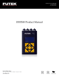
1
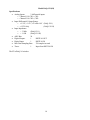
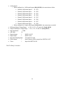
Version 2.2.0 Jmida Technology FT_ez_DAQ User’s Manual Table of Contents 1. Introduction ......................................................................................................................................... 3 2. System Requirements ......................................................................................................................... 3 3. Software Installation ........................................................................................................................... 4 4. 5. 3.1 Application software and USB driver installation ........................................................................................ 4 3.2 Windows 8 USB driver installation .............................................................................................................. 6 3.3 Windows Vista/XP/2000 USB driver installation......................................................................................... 6 FTezDAQ-2.0 Software ...................................................................................................................... 9 4.1 FTezDAQ-2.0 Data Acquisition Software .................................................................................................... 9 4.2 Icon Functions ............................................................................................................................................. 10 4.3 Device Type Selection ................................................................................................................................ 10 4.4 Analog Input Setting and Display ............................................................................................................... 11 4.5 Digital Input Setting and Display................................................................................................................ 12 4.6 Analog Output Channels Setting................................................................................................................. 12 4.7 Counters Input ............................................................................................................................................. 13 4.8 Digital Output Channels Settings ................................................................................................................ 13 4.9 Data Acquisition Starting Methods ............................................................................................................. 13 4.10 Data Graph Print ..................................................................................................................................... 15 4.11 Timer ...................................................................................................................................................... 15 DAQ Device Specifications .............................................................................................................. 16 5.1 DAQ-0311(A) ............................................................................................................................................. 16 5.2 DAQ-1211(H) ............................................................................................................................................. 17 5.3 DAQ-1411(H) ............................................................................................................................................. 19 5.4 DAQ-1811................................................................................................................................................... 21 5.5 MF-28 ......................................................................................................................................................... 24 5.6 MF-126 ....................................................................................................................................................... 26 2 1. Introduction Jmida (formerly Futek) ezDAQ multi-function data acquisition system is an integrated hardware and software system. It includes analog inputs, analog outputs, digital inputs/outputs, counters and timers. It is powered by PC USB port without external power supply needed. The application software FTezDAQ is designed for easy run in Windows® Operation System. Key Features: Multiple analog inputs ranges High analog input impedance Digital Outputs, can output TTL level voltage and PWM signal. Digital Input, 32bit Counters, Event triggers, Timer. Analog Outputs: o SIN waveform. o TRIANGLE waveform. o SAWTOOTH waveform. o User set voltage Full-speed USB communications Powered by USB Easy to use application software FTezDAQ runs in Windows® operation system. Specifications of different models are as below: Model DAQ-0311A DAQ-1211 DAQ-1211H DAQ-1411 DAQ-1411H DAQ-1811 MF-28 MF-126 1 1 2 1 1 2 1 1 4 1 1 4 1 1 8 2 2 8 >3MΩ 100 ±1.25V ±2.5V ±5V ±10V 2DI >3MΩ 320 ±1.25V ±2.5V ±5V ±10V 2DI 7MΩ 320 4DI >3MΩ 320 ±1.25V ±2.5V ±5V ±10V 4DI 7MΩ 320 8SE/4DI >3MΩ 320 (±)1.25V (±)2.5V (±)5V (±)10V Bridge Power Provided Analog Outputs DAC Bit N/A N/A N/A N/A N/A N/A N/A N/A N/A N/A N/A N/A Analog Output Modes N/A N/A N/A N/A N/A N/A 8SE/4DI >3MΩ 450 (±)1.25V (±)2.5V (±)5V (±)10V Yes 1 8 SIN Triangle Sawtooth Voltage 4 12 SIN Triangle Sawtooth Voltage Max Frequency PWM Output PWM Max Frequency Timers 32 bit Counters Max Frequency N/A N/A N/A 1 N/A N/A N/A N/A 1 N/A N/A N/A N/A 1 N/A N/A 1 1KHz 1 N/A N/A 1 1KHz 1 N/A N/A 1 1KHz 1 N/A 1KHz 2 1KHz 1 1 1MHz 1KHz 3 1MHz 1 2 66KHz Digital I/O Input Output Analog Inputs 12Bit 16Bit 24Bit Input Impedance Max Sample Rate SPS Analog Input Ranges 1 1 3 7 3 14 14SE 2SE/1DI ±1.25V ±1.25V 2. System Requirements The computer requires 32bit or higher Windows® Operation System with USB 1.0 or 2.0 ports. 3 400KΩ 31K 0~+10V 3. Software Installation 3.1 Application software and USB driver installation Download FTezDAQ_2_x_x.zip file from Jmida website support page, and unzip it, then run FTezDAQ-setup-2.2.0.exe. The following window will pop up. Select the folder which you want to install. Click “Next”, then select “Install this driver software anyway” 4 After the driver installation completed, click “Finish” and close the following windows. The USB driver and application software has been installed. **Note: For DAQ-1X11 and DAQ-0311A, PC may show the following message, 5 Please ignore this error message and close this window. 3.2 Windows 8 USB driver installation For Windows® 8 system, “Driver Signature Enforcement” must be disabled before installation. You need to take the following steps: (1). Windows Key + R (2). Enter shutdown.exe /r /o /f /t 00 (3). Click the "OK" button (4). System will restart to a "Choose an option" screen (5). Select "Troubleshoot" from "Choose an option" screen (6). Select "Advanced options" from "Troubleshoot" screen (7). Select "Windows Startup Settings" from "Advanced options" screen (8). Click "Restart" button (9). System will restart to "Advanced Boot Options" screen (10). Select "Disable Driver Signature Enforcement" Once the system starts, run the installation file as you would on Windows 7. When installation finishes, restart the system and “Driver Signature Enforcement” will get enabled automatically. 3.3 Windows Vista/XP/2000 USB driver installation For Windows® Vista/XP/2000 operation system, sometimes, when first time the device is connected to PC USB port, PC will show “Found New Hardware”. 6 Select “No, not this time”, then click “Next”. Select “Install the software automatically”, then”Next” Select “Continue Anyway” 7 Click “Finish” to complete the driver installation. Sometimes, PC will show “Found New Hardware” again, just repeat above steps. 8 4. FTezDAQ-2.0 Software 4.1 FTezDAQ-2.0 Data Acquisition Software The FTezDAQ-2.0 data acquisition software is easy to use and user friendly. User can start this program from PC “Start” menu, or create a short cut icon on the desktop. The following window will show up when run this program, For the different device type, the functions in the above window are little bit different base on different hardware specification. 9 4.2 Icon Functions The functions of the icons on the top left side are as below Start: Start data acquisition. Stop: Stop data acquisition. Save Settings: Save all settings, such as Device Type, Input Voltage Ranges, Sampling Rate, Analog Output Mode, Start Trigger, Channels selection, etc. The file is saved as xml format. Load Setting: Load the saved settings. Save Data: Save test result data for all channels which has been selected. The file is saved as txt format. Save Project: Save all settings and test data. The file is saved as xml format. Load Project: Load saved project. About: Software version. Exit Program: Exit the program and close the window. 4.3 Device Type Selection Pull down the Device Type selection window and select the device type which user purchased. 10 After select the Device Type, the dedicate window with functions which that device has will show up. The detailed functions for each device will describe later. 4.4 Analog Input Setting and Display From “Settings””Range” window, user can select the analog input voltage ranges. Check “Select” to select this channel will be measured. Input the Sampling Rate to set the data sampling rate for this channel. ( ** Max sampling rate is difference for different device. The max value of Sampling Rate is limited by the device). In the “Display” section, check “Graph”, will display the test result plot. 11 In the Y-axis window, if select “Voltage”, the window will display the plot for input voltage vs time. If select “Function Y”, the window will display the plot with the function of input voltage, user can input the coefficients base on the measured voltage to display the physical characters. 4.5 Digital Input Setting and Display Digital input channel setting and display are similar as analog, just set the sampling rate and check “select” to select the channel which will be measured. 4.6 Analog Output Channels Setting The analog output channel has different output mode: 12 It can output user defined voltage at “Voltage Value” mode. It also can output fixed amplitude Sin, Triangle and Sawtooth waveform, the frequency can be changed, normally the max frequency is 1KHz. 4.7 Counters Input Some device has digital input counters, they count the input voltage falling edges. 4.8 Digital Output Channels Settings Digital output channels can output TTL level digital signal or PWM waveform. When select output mode as “Status Value”, it will output the TTL signal High or Low. When select output mode as PWM Wave, it will output PWM waveform, user can input the frequency and duty ratio. 4.9 Data Acquisition Starting Methods There are several ways to start data acquisition. The “Start Trigger” can be: Manual Raising Edge Falling Edge 13 Except “Manual”, the trigger signal comes from Digital Input Channel 1. The “Stop Trigger” can be Manual Raising Edge Falling Edge Time Out If choose stop trigger mode as “Time Out”, user can define the test duration. If choose the Start Trigger and Stop Trigger are both Manual, when click “Start” icon the test; when click “Stop” icon will stop the test. 14 , will start If choose the Start Trigger is not Manual, after click “Start” icon trigger signal occurs. , the test will not start until the 4.10 Data Graph Print After the testing, if the “Graph” has been checked, the graph can be printed by click “Print”. 4.11 Timer User can use Digital Input Channel 1 as Start and Stop Trigger to measure external event timing. 15 5. DAQ Device Specifications This chapter describes the detailed specifications for different DAQ Models. 5.1 DAQ-0311(A) Model DAQ-0311 Model DAQ-0311A The main difference of DAQ-0311 and DAQ-0311A is: DAQ-0311 has 3 single ended analog inputs, CH1, CH2 and CH3; DAQ-0311A has 2 single ended analog inputs CH2 and CH3 and one differential analog input CH1+ and CH1-. Specifications: Analog Inputs: 3 Input voltage range: o 1.25V, 2.5V, 5V and 10V for single ended input o ±1.25V, ±2.5V, ±5V and ±10V for differential input (DAQ-0311A CH1) Input Impedance: > 3MΩ ADC Bits: 16 Digital Output: 1 DO 16 Digital Input: 1 Max Data Sampling Rate: DI 100 samples/second The FTezDAQ-2.0 window 5.2 DAQ-1211(H) 17 Model DAQ-1211(H) Specifications: Analog Inputs: 2 differential inputs o Channel1 CH1+, CH1o Channel2 CH2+, CH2 Input Differential Voltage Range: o ±1.25V, ±2.5V, ±5V and ±10V (DAQ-1211) o ±1.25V Only (DAQ-1211H) Input Impedance: o > 3 MΩ (DAQ-1211) o > 1 GΩ (DAQ-1211H) ADC Bits: 24 Digital Output: 1 DIGITAL OUT Digital Input: 1 DIGITAL IN Max Data Sampling Rate: 320 samples/second Timer: 1 Input from DIGITAL IN The FTezDAQ-2.0 window 18 5.3 DAQ-1411(H) Model DAQ-1411(H) Specifications: Analog Inputs: 4 differential inputs o Channel1 CH1+, CH119 o Channel2 CH2+, CH2o Channel3 CH3+, CH3o Channel4 CH4+, CH4Input Differential Voltage Range: o ±1.25V, ±2.5V, ±5V and ±10V (DAQ-1411) o ±1.25V Only (DAQ-1411H) Input Impedance: o > 3 MΩ (DAQ-1411) o > 1 GΩ (DAQ-1411H) ADC Bits: 24 Digital Output: 1 DIGITAL OUT Digital Input: 1 DIGITAL IN Max Data Sampling Rate: 320 samples/second PWM Output: 1 Max Frequency 1KHz, output from DIGITAL OUT Timer: 1 Input from DIGITAL IN The FTezDAQ-2.0 window 20 5.4 DAQ-1811 The analog inputs of DAQ-1811 can be configured as 8 single ended inputs (DAQ-1811S) or 4 differential inputs (DAQ-1811D). Model DAQ-1811 Specifications: 21 Analog Inputs: o When configured as 4 differential inputs (DAQ-1811D), the connections as below Channel 1 differential input + CH1 Channel 1 differential input - CH2 Channel 2 differential input + CH3 Channel 2 differential input - CH4 Channel 3 differential input + CH5 Channel 3 differential input - CH6 Channel 4 differential input + CH7 Channel 4 differential input – CH8 o When configured as 8 single ended inputs (DAQ-1811S), the connections as marked. Differential Input Voltage Range: ±1.25V, ±2.5V, ±5V and ±10V (DAQ-1811D) Single Ended Input Voltage Range: 1.25V, 2.5V, 5V and 10V (DAQ-1811S) Input Impedance: > 3MΩ ADC Bits: 24 Digital Output: 1 DIGITAL OUT Digital Input: 1 DIGITAL IN Max Data Sampling Rate: 320 samples/second PWM Output: 1 Max Frequency 1KHz, output from DIGITAL OUT Timer: 1 Input from DIGITAL IN The FTezDAQ-2.0 window 22 When Configured as DAQ-1811D When Configured as DAQ-1811S 23 5.5 MF-28 The analog inputs of MF-28 can be configured as 8 single ended inputs (MF-28S) or 4 differential inputs (MF-28D). Model MF-28 Specifications: Analog Inputs: o When configured as 4 differential inputs (MF-28D), the connections as below Channel 1 differential input + CH1 Channel 1 differential input - CH2 Channel 2 differential input + CH3 Channel 2 differential input - CH4 Channel 3 differential input + CH5 Channel 3 differential input - CH6 Channel 4 differential input + CH7 Channel 4 differential input – CH8 o When configured as 8 single ended inputs (MF-28S), the connections as marked. Differential Input Voltage Range: ±1.25V, ±2.5V, ±5V and ±10V (MF-28D) Single Ended Input Voltage Range: 1.25V, 2.5V, 5V and 10V (MF-28S) Input Impedance: > 3MΩ ADC Bits: 24 Digital Output: 2 DO1, DO2 Digital Input: 2 o Digital Input Channel 1: DI1 o Digital Counter Input: DI2 Max Data Sampling Rate: 450 samples/second PWM Output: 1 Max Frequency 1KHz, output from DO1 and DO2 DC Power Output: 1 4.7V Max 50mA, output from PWR 32 bits Counter: 1 Input from DI2 Timer: 1 Input from DI1 Analog Output: 1 Output from VOUT, Range 0 to 4V, 8bit DAC 24 o Output Waveform: Max Frequency 1KHz; fixed amplitude 4V. Sin Triangle Sawtooth o User Set Voltage 0 to 4V. The FTezDAQ-2.0 window When Configured as DAQ-MF28D 25 When Configured as DAQ-MF28S 5.6 MF-126 26 Model MF-126 Specifications: Analog Inputs: 14 A1 to A14 Input Voltage Range: 0 to10V Input Impedance: ≥ 400KΩ ADC Bits: 12 Digital Output: 3 D6(DOCH1), D8(DOCH2), D9(DOCH3) Digital Input: 5 D1(DICH1), D2(DICH2), D3(DICH3), D4(DICH4), D5(DICH5) Max Data Sampling Rate: 31K samples/second PWM Output: 3 o D6(DOCH1) Max Frequency 1MHz, o D8(DOCH2) Max Frequency 1KHz, o D9(DOCH3) Max Frequency 1MHz, 32 bits Counter: 2 Max Frequency 66KHz, Falling Edge Count o Counter1: D7 (CNTR1) o Counter2: D10 (CNTR2) Timer: 1 Input from D1 Analog Output: 4 12bit DAC, Range 0 to 2.5V. VOUT1 to VOUT4 o Output Waveform: Max Frequency 1KHz; fixed amplitude 2.5V. Sin Triangle Sawtooth o User Set Voltage, Range 0 to 2.5V. The FTezDAQ-2.0 window 27 28