1
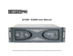
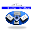
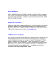
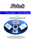
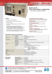
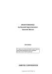
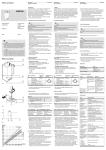
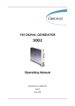
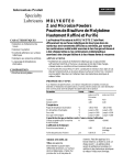
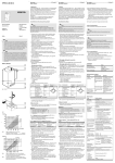
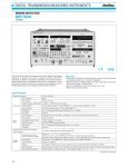
RADIO COMMUNICATIONS TEST INSTRUMENTS
DIGITAL MODULATION SIGNAL GENERATOR
MG3670B/C, MG3671A/B
300 kHz to 2.25/2.75 GHz
GPIB
The MG3670B/C, MG3671A/B is a digital modulation signal generator equipped with a high-performance quadrature modulator. It outputs the signals needed to develop, test and evaluate digital mobile
communications equipment and related devices with expansion units.
The MG3670B/C, MG3671A/B covers the frequency range from 300
kHz to 2.25 GHz (MG3670B/C)/300 kHz to 2.75 GHz (MG3671A/B),
and provides a stable and precise output as well as spectrum purity
up to a maximum output of +13 dBm, even with modulation. In addition to testing receiver sensitivity and excess input, it can be used for
testing IF stage performance and for evaluating device quality. A
CMOS-level mode is provided for I/Q signal input. The input frequency band covers the CDMA spread spectrum band, expanding
the range of applications.
The MG3670C and MG3671B are expanded applications by rear
panel extension connectors to use for auxiliary signal output function
special to communication system. MG3670B/C and MG3671A/B can
be used in combination with up to seven modulation units, and a
burst function unit, simultaneously.
The MG0301C/0302A/0305A/0307A/0311A modulation units have a
continuous data generator capable of generating arbitrarily-programmable data signals and ITU-T specification PN9/15 stage PRBS signals, as well as band-limiting filters, and they can output I/Q baseband signals.
The MG0303A Burst Function Unit uses the frame and slot configuration stipulated by various communication systems, and has a modulation pattern generator function and a function for ramp control of
carrier burst signals. It can also handle data editing and scrambling.
The MG0310A Modulation Unit generates SS + QPSK/OQPSK modulated (1.2288 Mcps) I/Q baseband signals, supporting the CDMA
system (TIA/EIA/IS-95) used in US Digital Cellular Systems and the
US Personal Communications Service (PCS).
Anritsu-developed DSP and ASIC technology is used in the MG0310A
to achieve superior waveform quality factor (ρ) and spurious emission characteristics. Channel multiplexed signals are supported for
both forward and reverse links.
With two MG0310A units mounted in the MG3670C/3671B, all the
test signals required to conform to TIA/EIA/IS-95, -97 & -98 can be
generated. Simultaneous outputs from the rear extension connectors
using long & short codes, etc., support a wide range of applications
including RF related tests, IF stage performance tests, and device
and module quality evaluation. (Option 25 is required to install the
MG0310A in the MG3670B/3671A. The auxiliary signal output function is not installed, so long/short codes cannot be output.)
236
The MG0312A QPSK Modulation Unit generates QPSK/OQPSK
modulated I/O baseband signals at 8 high speed bit rates between
500 kbps and 2.4576 Mbps. Built in modulation data includes NP7/
PN9/PN15/PN23 pseudorandom patterns. Use over a wide range is
supported by multiple baseband filters, and the Phase Encoding
function which allows modulation data to be voluntarily phase mapped
onto a constellation.
At the 2.4576 Mbps bit rate, the evaluation of transmission section
devices and modules can be performed such as RF power amplifier
for CDMA mobile station.
Communication
systems
Units
PHS, PDC, PDC_H,
NADC, TFTS
MG0301C
π/4 DQPSK Modulation Unit
GSM, PCN, CT2
MG0302A
GMSK Modulation Unit
DECT
MG0305A
GFSK Modulation Unit
PACS, WCPE, PHS
MG0307A
π/4 DQPSK Modulation Unit
TETRA
MG0311A
π/4 DQPSK Modulation Unit
IS-95
MG0303B
Burst Function Unit
MG0310A CDMA Modulation Unit
MG0312A QPSK Modulation Unit
Features
• Compatible with communication system measurement signals of
Japan, North America and Europe
• High modulation accuracy (≤1.8% rms vector error)
• Outputs modulation signals suited to each communication systems
• Internal pattern generator with data-editing and scrambling functions
• Outputs IS-95 channel multiplex signal
RADIO COMMUNICATIONS TEST INSTRUMENTS
Basic performance
• I/Q signal I/O over broad frequency range
A quadrature modulator is built in, and external I/Q signals can be input to enable use with a variety of digital modulation modes, including QPSK, 8PSK and M16QAM. The modulation band for I/Q input
signals is broad, covering the CDMA spread spectrum bandwidth.
Further, by adding an expansion unit, I/Q signal output can be obtained from the internal data generator. Either 50 Ω or CMOS-level
compatibility can be selected for I/Q signals. Functions for adjusting
the level balance, offset and phase are also provided for greater utility in evaluating modulators/demodulators and other devices.
Level (dB)
0
–1
Output level frequency characteristics
–2
–3
(50 Ω/0.5 Vrms mode)
30 k
100 k 300 k
1M
3M
I/Q signal input frequency (Hz)
10 M
Frequency response for I/Q external modulation (typical values)
• Excellent spectral purity
6
The SSB phase noise characteristic is an excellent –120 dBc/Hz or
less (100 kHz offset). The adjacent channel power characteristic excels as the interference signal source during modulation.
Output level accuracy at 1.9 GHz
• High modulation accuracy
A vector error of less than 1.8%rms is assured for output levels up to
+5 dBm over the entire operating frequency range. This high modulation accuracy is also achieved when the expansion units are used.
Even when the MG0301C and MG0303B units are installed and π/4
DQPSK modulation burst signals are generated, the vector error is
less than 1.8%rms. The MG3670B/C, MG3671A/B enables measurement and quality evaluation of receivers and other devices with more
than adequate precision.
Functions and performances with expansion unit
• Frame structure and data
SSB phase noise at 1.9 GHz
• Large output level
Through use of new AGC circuitry, the MG3670B/C, MG3671A/B
produces a highly precise output at levels down to –143 dBm with
stable frequency characteristics, not only for output of unmodulated
signals, but also with π/4 DQPSK modulation accompanied by amplitude fluctuations, and when outputting burst signals. The MG3670B/C,
MG3671A/B can generate a high output level of up to +13 dBm over
a broad range of frequencies, so amplifiers are not needed even
when testing receivers for excess input, and in testing other devices.
TDMA
The MG0303B incorporates TDMA frames for various kinds of communication systems, as well as modulation patterns for each time
slot.
Modulation patterns for device evaluation and for up/down communication channels are provided, and are output at the timing required
by the system. Hence the MG3670B/C, MG3671A/B can generate the
burst signals needed to measure various digital communication systems.
Time slots specified for different communication systems can be selected freely. There is considerable freedom in choosing the modulation pattern within slots; either a PN9 or PN15 TCH segment can be
chosen, and part of the data outside the TCH segment can be edited.
The pattern memory function can be used to store and recall patterns.
A data scrambling function is provided as standard, and any initial
code can be set permitting more sophisticated evaluations and diagnostics using the MG3670B/C, MG3671A/B as a supposed base station and mobile equipment.
The internal modulation pattern can also be driven by an external
clock, so margin tests can be conducted by varying the clock pulse.
237
RADIO COMMUNICATIONS TEST INSTRUMENTS
Pattern edit display
CDMA
MG0310A has various TIA/EIA/IS-95 frame format and encoder
functions built-in for each channel types. For example, frame format
of signalling, communication and Multiplex Option 1 are provided to
support Rate Set 1 (1200 ... 9600 bps) and Rate Set 2 (1800 ...
14400 bps) for the Traffic Channel. In combination with the Burst
Randomizer function, this allows system support at all rates, even for
reverse links. For internal data you can select either a PN7, 9 or 15
pseudo-random pattern, or a user settable 16-bit data repeating pattern, all fully editable. Operation can be from internal RAM user-definable sequence data or from external serial data.
Slot rise time waveform
• Superior spurious emission characteristics
Spurious emissions are guaranteed to be lower than –60 dBc (±900
kHz detuning, 30 kHz bandwidth) and –70 dBc (±1.98 MHz detuning,
30 kHz bandwidth) with MG0310A installed in the MG3670C/3671B
mainframe (for output level: 0dBm, baseband filter: SPEC 2). Using
this baseband filter gives a waveform quality factor (ρ) of 0.999 or
better. This filter conforms to IS-95, providing 3-step switching.
Selecting the best step for each evaluation item gives even higher
performance. This excellent basic performance in a standard digital
modulation signal generator makes it the ideal choice for the development and manufacture of digital mobile wireless equipment and
related devices/modules.
Pattern setting display
• Excellent leakage power characteristics during carrier-off
The rising and falling edges of burst signals have a gentle waveform
with a duration equivalent to two symbols, and the leakage power
during carrier-off characteristics are excellent.
PHS
238
Modulation spectrum
(with MG0310A installed in the MG3670C/3671B)
RADIO COMMUNICATIONS TEST INSTRUMENTS
Specifications (refer to the MG3670B/C, MG3671A/B data sheet for more details.)
• MG3670B/C, MG3671A/B Digital Modulation Signal Generator
Frequency range
Carrier
frequency
300 kHz to 2250 MHz (MG3670B/C), 300 kHz to 2750 MHz (MG3671A/B)
Accuracy
Depends on installed reference oscillator*1
Internal reference
oscillator
Frequency: 10 MHz
Start-up characteristics: ≤1 x 10⁻⁷/day (after 30-min. warm-up), ≤5 x 10⁻⁸/day (after 60-min. warm-up)
Aging rate: ≤2 x 10⁻⁸/day (after 24-h warm-up)
Temperature characteristics: ≤±5 x 10⁻⁸ (0˚ to 50˚C)
External reference
input
10 MHz or 13 MHz (±10 ppm), 2 to 5 Vp-p, BNC connector (rear panel)
Reference output
10 MHz, 2 to 5 Vp-p, BNC connector (rear panel)
Level range
–143 to +13 dBm (resolution: 0.1 dB)
Frequency response
≤±1 dB (at 0 dBm output)
Output level/frequency
≤1000 MHz
–33 to +13 dBm
±1 dB
±2 dB
–123 to –33.1 dBm
±1.5 dB
±2 dB
–136 to –123.1 dBm
±3 dB
±4 dB
Level accuracy
Output
Signal purity
Digital
modulation
Pulse
modulation
Memory
function
Other
functions
*
*
*
>1000 MHz
Impedance
50 Ω, N-type connector
Continuously
variable level
Continuously variable output over 20 dB range (+8 to –12 dB) in 0.1 dB steps within upper and lower limits of any
output level
Level unit
dBm, dBµ, µV, mV, V (dBµ, µV, mV, V selected terminate/open voltage display)
Interference
radiation
≤1 µV Measured 25 mm from cabinet (except rear panel) with two-turn 25 mm diameter loop antenna, terminated
with 50 Ω load, ≤+5 dBm output, carrier wave
Spurious
≤–65 dBc (≥100 kHz offset, ≤±100 MHz bandwidth), ≤–50 dBc (≥100 kHz offset, full band),
≤–40 dBc [spurious of (5.4–Fout) GHz at ≥2.65 GHz], ≤–30 dBc (harmonics)
SSB phase noise
≤–120 dBc/Hz (100 kHz offset, carrier wave)
Internal modulation
Depends on installed modulation unit (MG0301C/0302A/0305A/0307A/0310A/0311A/0312A)
External
modulation
Any modulation using I/Q input signal
Input frequency: DC to 1.2 MHz*2
Input level: √ I2 ± Q2 ≤0.5 Vrms, BNC connector I/Q ≤1.5 Vp-p (50 Ω), I/Q ≤10% to 100% of 1.5 Vp-p (CMOS)
Vector error: ≤1.8%rms (I/Q input level: 1 Vrms/50 Ω, at ≤+5 dBm output)
*
6
*
I/Q output
Outputs I/Q signal at internal modulation (MG0301C/0302A/0305A/0307A/0310A/0311A/0312A installed)
Input
TTL level, BNC connector, polarity selectable
On/off ratio
≥40 dB (at ≥0 dBm output)
Transition time
≤2 µs, minimum pulse width: 10 µs
Frequency memory
1000 carrier frequencies (save and recall)
Parameter memory
100 panel settings (save and recall)
Relative display
Carrier frequency, output level
I/Q signal adjustment
Offset, balance, phase (only output) of I/Q input/output signal
Backup
Last settings stored at power-off
Reverse power
protection
Maximum reverse input power: 50 W (<1000 MHz), 25 W (≥1000 MHz), ±50 V (DC)
GPIB
All functions except power switch and panel lock switch controlled
Interface function: SH1, AH1, T6, L4, SR1, RL1, PP0, DC1, DT0, C0, E2
Operating temperature
0˚ to 50˚C
Power
100 to 120/200 to 240 Vac (switchable), 47.5 to 63 Hz, ≤550 VA
Dimensions and mass
(426±5) W x (221.5±4) H x (451±5) D mm, ≤27 kg
EMC*3
EN55011: 1991, Group 1, Class A
EN50082-1: 1992
Safety
EN61010-1: 1993 (Installation Category ΙΙ, Pollution Degree ΙΙ)
1: Internal reference oscillator accuracy: 2 x 10⁻⁸/day (23˚ ±5˚C), calibrated after 24-h operation
2: Refer to the “Frequency response for I/Q external modulation (typical value)” on page 237 for the input frequency range. Typical values are given for reference only to assist in the use of this instrument, and are not guaranteed specifications.
3: Electromagnetic compatibility
MG0301C π /4 DQPSK Modulation Unit (incorporated in the MG3670B/C, MG3671A/B)
Applicable communication
system
PDC, PDC_H, PHS, NADC, TFTS
Modulation system
π/4 DQPSK
Vector error
I/Q signal: ≤1.5%rms (at 1 Vrms/50 Ω output), RF signal: ≤1.8%rms (at ≤+5 dBm output)
Internal modulation data
Pseudorandom pattern: PN15, PN9
Free 4-bit repetition pattern (ex: 1010, 1111)
External modulation data
DATA CLOCK: Covering ±5% of bit rate
DATA: Digital data synchronized with DATA CLOCK
SYMBOL CLOCK: Clock specified by DATA synchronized with DATA CLOCK
TTL level, BNC connector, polarity selectable
Continued on next page
239
RADIO COMMUNICATIONS TEST INSTRUMENTS
I/Q signal output
Selectable 50 Ω or CMOS (600 Ω), BNC connector
50 Ω setting: 1 Vp-p ±2% (modulation data: 0000, TFTS: 1111)
CMOS setting: Variable in 10% steps over range of 10% to 100% of 1 Vp-p ±2%
Variable offset voltage; 0 to 4 V (1 mV steps)
PDC, PDC_H
Carrier frequency range: 300 kHz to 2250 MHz*1 (incorporated in the MG3670B/C), 300 kHz to 2750 MHz (incorporated in the MG3671A/B)
Bit rate: 42 kbps
Baseband filter: Root Nyquist (α = 0.5), Nyquist (α = 0.5)
PHS
Carrier frequency range: 1 to 2250 MHz*1 (incorporated in the MG3670B/C), 1 to 2750 MHz (incorporated in the MG3671A/B)
Bit rate: 384 kbps
Baseband filter: Root Nyquist (α = 0.5), Nyquist (α = 0.5)
Adjacent channel leakage power ratio: ≤–74 dB (600/900 kHz offset, ±96 kHz band, ≥10 MHz)*2
NADC
Carrier frequency range: 300 kHz to 2250 MHz*1 (incorporated in the MG3670B/C), 300 kHz to 2750 MHz (incorporated in the MG3671A/B)
Bit rate: 48.6 kbps
Baseband filter: Root Nyquist (α = 0.35), Nyquist (α = 0.35)
TFTS
Carrier frequency range: 300 kHz to 2250 MHz*1 (incorporated in the MG3670B/C), 300 kHz to 2750 MHz (incorporated in the MG3671A/B)
Bit rate: 44.2 kbps
Baseband filter: Root Nyquist (α = 0.4), Nyquist (α = 0.4)
upper frequency is limited by the specifications of the main frame in which this unit is installed.
*1:2: The
Applicable when this unit is installed in MG3670B/C, MG3671A/B.
* Not
applicable when this unit is installed in MG3670A.
MG0302A GMSK Modulation Unit (incorporated in the MG3670B/C, MG3671A/B)
Applicable communication system
GSM, DCS1800 (PCN), CT2
Modulation system
GMSK
Phase error
I/Q signal: ≤1˚ rms, ≤3˚ peak (at 1 Vrms/50 Ω output, 25˚ ±5˚C, after 30 min. warm-up)
≤2˚ rms, ≤5˚ peak (at 1 Vrms/50 Ω output)
RF signal: ≤1˚ rms, ≤3˚ peak (at ≤+5 dBm output, 25˚ ±5˚C, after 30 min. warm-up)
≤2˚ rms, ≤5˚ peak (at ≤+5 dBm output)
Internal modulation data
Pseudorandom pattern: PN15, PN9, free 4-bit repetition pattern (ex: 1010, 1111)
External modulation data
DATA CLOCK: Covering ±5% of bit rate
DATA: Digital data synchronized with DATA CLOCK
TTL level, BNC connector, polarity selectable
I/Q signal output
Selectable 50 Ω or CMOS (600 Ω), BNC connector
50 Ω setting: 1 Vp-p ±2% (modulation data: 0000)
CMOS setting: Variable in 10% steps over range of 10% to 100% of 1 Vp-p ±2% (modulation data: 0000)
Variable offset voltage; 0 to 4 V (1 mV steps)
GSM/PCN (DCS1800)
Carrier wave frequency range:
1 to 2250 MHz*1 (incorporated in the MG3670B/C), 1 to 2750 MHz (incorporated in the MG3671A/B)
Bit rate: 270.833 kbps
Baseband filter: Gaussian filter BbT = 0.3
CT2
Carrier wave frequency range:
300 kHz to 2250 MHz*1(incorporated in the MG3670B/C), 300 kHz to 2750 MHz (incorporated in the MG3671A/B)
Bit rate: 72 kbps
Baseband filter: Gaussian filter BbT = 0.5
*1: The upper frequency is limited by the specifications of the main frame in which this unit is installed.
MG0305A GFSK Modulation Unit (incorporated in the MG3670B/C, MG3671A/B)
Applicable communication system
DECT
Modulation system
GFSK
Vector error
I/Q signal: ≤12 kHz (at 1 Vrms/50 Ω output), RF signal: ≤12 kHz (at ≤+5 dBm output, modulation data: FFFF)
Internal modulation data
Pseudorandom pattern: PN15/PN9
Free 16-bit repetition pattern (ex: 0F0F, 00FF)
External modulation data
DATA CLOCK: Covering ±5% of bit rate
DATA: Digital data synchronized with DATA CLOCK
TTL level, BNC connector, polarity selectable
I/Q signal output
Selectable 50 Ω or CMOS (600 Ω), BNC connector
At modulation data
50 Ω setting: 1 Vp-p ±6% (modulation data: 0000)
CMOS setting: Variable in 10% steps over range of 10% to 100% of 1 Vp-p ±6%
Variable offset voltage; 0 to 4 V in 1 mV steps (modulation data: 0000)
Phase polarity
Polarity reversal of frequency deviation during modulation is possible.
DECT
Carrier frequency range: 5 to 2250 MHz*1 (incorporated in the MG3670B/C), 5 to 2750 MHz (incorporated in the MG3671A/B)
Bit rate: 1152 kbps
Deviation ratio: 70% (202 kHz), 90% (259 kHz), 100% (288 kHz), 140% (403 kHz), at BbT=0.5
Baseband filter: Gaussian filter BbT = 0.4, 0.5, 0.6, at deviation ratio = 100%
*1: The upper frequency is limited by the specifications of the main frame in which this unit is installed.
240
RADIO COMMUNICATIONS TEST INSTRUMENTS
MG0307A π /4 DQPSK Modulation Unit (incorporated in the MG3670B/C, MG3671A/B)
Applicable communication system
PACS, WCPE, PHS
Modulation system
π/4 DQPSK
Vector error
I/Q signal: ≤1.5%rms (at 1 Vrms/50 Ω output)
RF signal: ≤1.8%rms (at ≤+5 dBm output)
Internal data mode
Pseudorandom pattern: PN15, PN9
Free 16-bit repetition pattern (ex: 0F0F, 00FF): WCPE
Free 4-bit repetition pattern (ex: 0101, 0011): PACS, PHS
External data mode
DATA CLOCK: Covering ±5% of bit rate
DATA: Digital data synchronized with DATA CLOCK
SYMBOL CLOCK: Clock specified by DATA synchronized with DATA CLOCK
TTL level, BNC connector, polarity selectable
I/Q signal output
Selectable 50 Ω or CMOS (600 Ω), BNC connector
50 Ω setting: 1 Vp-p ±5% (modulation data: 0000)
CMOS setting: Variable in 10% steps over range of 10% to 100% of 1 Vp-p ±5%; variable offset voltage: 0 to 4 V in 1 mV
steps (modulation data: 0000)
Phase encode function
Invertible phase polarity at modulation
PACS
Carrier frequency range: 1 to 2250 MHz*1 (incorporated in the MG3670B/C), 1 to 2750 MHz (incorporated in the MG3671A/B)
Bit rate: 384 kbps
Baseband filter: Root Nyquist (α = 0.5), Nyquist (α = 0.5)
WCPE
Carrier frequency range: 5 to 2250 MHz*1 (incorporated in the MG3670B/C), 5 to 2750 MHz (incorporated in the MG3671A/B)
Bit rate: 1152 kbps
Baseband filter: Root Nyquist (α = 0.5), Nyquist (α = 0.5)
PHS
Carrier frequency range: 1 to 2250 MHz*1 (incorporated in the MG3670B/C), 1 to 2750 MHz (incorporated in the MG3671A/B)
Bit rate: 384 kbps
Baseband filter: Root Nyquist (α = 0.5), Nyquist (α = 0.5)
Adjacent channel leakage power ratio: ≤–74 dB (600/900 kHz offset, ±96 kHz band, ≥10 MHz)*2
upper frequency is limited by the specifications of the main frame in which this unit is installed.
*1:2: The
Applicable when this unit is installed in MG3670B/C, MG3671A/B.
* Not
applicable when this unit is installed in MG3670A.
6
MG0311A π/4 DQPSK Modulation Unit (incorporated in MG3670B/C, MG3671A/B)
Applicable communication system
TETRA
Modulation system
π/4 DQPSK
Vector error
I/Q signal: ≤1.5%rms (at 50 Ω output)
RF signal: ≤1.8%rms (at ≤+5 dBm output)
Internal modulation data
Pseudorandom pattern: PN15/PN9
Free 4-bit repetition pattern (ex: 0101, 0011)
External modulation data
DATA CLOCK: Covering ±5% of bit rate
DATA: Digital data synchronized with DATA CLOCK
SYMBOL CLOCK: Clock specified by DATA synchronized with DATA CLOCK
TTL level, BNC connector, polarity selectable
*
I/Q signal output
Phase encode function
Carrier frequency
TETRA
Selectable 50 Ω or CMOS (600 Ω), BNC connector
50 Ω setting: 1 Vp-p ±5% (modulation data: 0000)
CMOS setting: Variable in 10% steps over range of 10% to 100% of 1 Vp-p ±5%;
Variable offset voltage: 0 to 4 V in 1 mV steps (modulation data: 0000)
Invertible phase change polarity at modulation
300 kHz to 2250 MHz*1 (incorporated in MG3670B/C), 300 kHz to 2750 MHz (incorporated in MG3671A/B)
Bit rate
36 kbps
Baseband filter
Root Nyquist (α = 0.35), Nyquist (α = 0.35)
Adjacent channel
leakage power ratio
≤–48 dB (25 kHz offset, ±9 kHz band)
≤–67 dB (50 kHz offset, ±9 kHz band)
*1: The upper frequency is limited by the specifications of the main frame in which this unit is installed.
MG0303B Burst Function Unit (incorporated in the MG3670B/C, MG3671A/B)
Applicable communication system
PDC, PDC_H, PHS, NADC, TFTS (with MG0301C)
GSM, PCN (DCS1800), CT2 (with MG0302A)
DECT (with MG0305A)
PACS, WCPE, PHS (with MG0307A)
TETRA (with MG0311A)
Internal data mode
TDMA framing specified for each system; modulation in each time slot using any internal modulation data
Internal data
Pseudorandom pattern: PN15/PN9*1 (for device)
Specified pattern based on communication channel format specified for each system:
Up/down communication channel, VOX signal control
TCH section consists of pseudorandom pattern PN15/PN9*1
External data mode
DATA CLOCK: Covering ±5% of bit rate
DATA: Digital data synchronized with DATA CLOCK
SYMBOL CLOCK: Clock specified by DATA synchronized with DATA CLOCK
BURST GATE: Burst signal synchronized with DATA CLOCK (on: ≥14 symbols, off: ≥8 symbols)
TTL level, BNC connector, polarity selectable
Modulation
signal
Continued on next page
241
RADIO COMMUNICATIONS TEST INSTRUMENTS
Burst trigger input
Control
signal
output
RF output
Burst trigger output
Outputs 1-symbol wide pulse at same cycle as burst waveform output at internal modulation
TTL level, BNC connector (rear panel), polarity selectable
Pattern sync output
Following outputs selectable at internal modulation
PN CLOCK: Data clock corresponding to pseudorandom pattern part
PN GATE : Gate signal corresponding to pseudorandom pattern part
RF GATE : Signal for controlling pulse modulator in accordance with burst signal output
TTL level, BNC connector (rear panel)
Burst gate output
Outputs gate signal corresponding to burst waveform output at internal modulation
TTL level, BNC connector (rear panel), polarity selectable
Burst on/off ratio
≥80 dB (+5 dBm output, PDC, PDC_H, NADC, CT2, TFTS, TETRA), ≥75 dB (+5 dBm output, PHS, GSM, PCN, PACS),
≥70 dB (+5 dBm output, DECT, WCPE)
Rise/fall time
Memory (pattern memory)
NADC
PDC
PDC_H
PHS
TFTS
GSM, PCN
(DCS1800)
CT2
DECT
Burst wave output synchronized with trigger input signal of burst repetition rate (frame cycle) at internal modulation
Input period: ≤burst repetition rate ±1 symbol [PDC, PDC_H, PHS, NADC, GSM, PCN (DCS1800), CT2, DECT, PACS,
WCPE, TETRA], ≤burst repetition rate ±1/2 symbol (TFTS)
TTL level, BNC connector (rear panel), polarity selectable
Equivalent to 2 symbols
Max. 100 patterns/system (save and recall of internal modulation pattern data)
Burst repetition rate
20 ms
Slot configuration
For device, up/down communication channel
Output slot select
On/off selectable for any slots of slot 0 to slot 2 (excluding all slots off)
Edit function
SYNC/SACCH/CDVCC: Any data, DATA: PN9, PN15*1 selectable
Burst repetition rate
20 ms (PPC), 40 ms (PDC_H)
Slot configuration
For device, up/down communication channel, up VOX control
Output slot select
On/off selectable for any slots of slot 0 to slot 2 (PDC)/slot 5 (PDC_H)
Edit function
SW/CC/SACCH: Any data, TCH: PN9, PN15*1 selectable
Scramble function
TCH + SF + SACCH scramble on/off, any scramble code setting
Burst repetition rate
5 ms
Slot configuration
For device, up/down communication channel, VOX control
*excluding all slots off
Output slot select
On/off selectable for any slots of slot 1 to slot 4 (excluding all slots off)
Edit function
UW/SA: Any data, TCH: PN9, PN15*1 selectable
Scramble function
TCH + CRC, scramble and secret scramble on/off, any scramble code setting
Adjacent channel
power leakage ratio
≤–74 dB (600/900 kHz offset, ±96 kHz band, ≥10 MHz)*2
Burst repetition rate
80 ms
Slot configuration
For device, up/down communication channel
Output slot select
On/off selectable for any slots of slot 0 to slot 16 (Device/UP TCH: Slots 16 is off at all time, excluding all slots off.)
Edit function
S: Any data, DATA: PN9, PN15*1 selectable
Burst repetition rate
4.615 ms
Slot configuration
For device, normal burst (communication channel)
Output slot select
On/off selectable for any slots of slot 0 to slot 7 (excluding all slots off)
Edit function
TS: Any data, E: PN9, PN15*1 selectable
Burst repetition rate
2 ms
Slot configuration
Up/down communication channel (MUX 1.2, MUX 1.4, MUX 2)
Edit function
D, B, Da, Db, CHM/SYNC data selectable
Scramble function
B scramble on/off, any scramble code setting
Burst repetition rate
10 ms
Slot configuration
For device, up/down communication channel
Output slot select
Full slot: Slot 0 to slot 11 (down channel), slot 12 to slot 23 (up channel)
Half slot: Slot 0-0 to slot 11-1 (down channel), slot 12-0 to slot 23-1 (up channel)
Double slot: Slot 0 to slot 10 (down channel), slot 12 to slot 22 (up channel)
On/off selectable for any slots (excluding all slots off)
*
PACS
WCPE
Edit function
S, H, T: Any data
D: PN15/PN9*1, all-0 or all-1 selectable (for device evaluation)
D: PN15/PN9*1, TEST or REP-8 bits any data selectable (for communication channel)
Burst repetition rate
2.5 ms
Slot configuration
For device, up/down communication channel
Output slot select
On/off selectable for any slots of slot 0 to slot 7 (excluding all slots off)
Edit function
PN: PN9, PN15*1 selectable (for device), DE/SC/R/SYC/PCC: Any data, FC: PN9*1, PN15*1, all-0 or all-1 selectable
(PN15 selectable only for 1 slot)
Burst repetition rate
10 ms
Slot configuration
For device, up/down communication channel
Output slot select
Full slot: Slot 0 to slot 11 (down), slot 12 to slot 23 (up), Half slot: Slot 0-0 to slot 11-1 (down), slot 12-0 to slot 23-1 (up)
Double slot: Slot 0 to slot 10 (down), slot 12 to slot 22 (up)
On/off selectable for any slots (excluding all slots off)
Edit function
S/H/T: Any data
D: PN9*1, PN15*1, all-0 or all-1 selectable (for device)
D: PN9*1, PN15*1, TEST or REP 8-bits any data selectable (for communication channel)
*
Continued on next page
242
RADIO COMMUNICATIONS TEST INSTRUMENTS
PHS
Burst repetition rate
5 ms
Slot configuration
For device, up/down communication channel, VOX control, sync burst
Output slot select
On/off selectable for any slots of slot 1 to slot 4 (excluding all slots off)
Edit function
UW/SA etc.: Any data, TCH: PN9, PN15*1 selectable
Scramble function
TCH + CRC, scramble on/off, any scramble code setting
Adjacent channel
leakage power ratio
≤–74 dB (600/900 kHz offset, ±96 kHz band, ≥10 MHz)*2
Burst repetition rate
V + D mode: 1.02; Excluding CH13, 255 to 30000 symbols; CH13
PDO mode: 1.00; Excluding CH14, 126 to 30000 symbols; CH14
Burst pattern
Following channel types selectable
V + D mode: CH1, CH2, CH3, CH4, CH13; Downlink, CH7, CH8, CH9, CH10, CH11; Uplink
PDO mode: CH5, CH6, CH14; Downlink, CH12; Uplink
Slot configuration
V + D mode: DEVICE, NORMAL, SYNC; Downlink, DEVICE NORMAL, CONTROL; Uplink
PDO mode: NORMAL, SYNC; Downlink, START, EVEN, ODD, END; Uplink
Output slot select
V + D mode: On/off selectable for any slots of slot 1 to slot 4 (excluding CH13 and all slots off)
Frame 1 to Frame 17 set to the same values
PDO mode: Variable slot numbers of slot 1 to slot 150 (excluding CH14)
Edit function
V + D mode: Downlink NORMAL; Any SB, SSB, NTS field data
SYNC; Any FC, SSB1, STS, SBB, SB2 field data
Uplink
NORMAL; Any SB, NTS field data
CONTROL; Any SCB, ETS field data
PDO mode: Downlink SYNC; Any FC, SB, STS field data
NORMAL; Any SB, NTS field data
Uplink
START; Any ETS, SB field data, R bit Length
EVEN; Any NTS field data
Scramble function
Any scramble code setting
TETRA
*
*
1: The pseudorandom pattern in each slot has a different phase, and its pattern is continuous within the data field of slots.
2: Applicable when this unit is installed in MG3670B/C, MG3671A/B. Not applicable when this unit is installed in MG3670A.
6
MG0310A CDMA Modulation Unit (incorporated in the MG3670C/3671B)
Carrier frequency range
4 kHz to 2250 MHz (MG3670C), 4 kHz to 2750 MHz (MG3671B)
RF output level
–143 to +8 dBm, 0.1 dB steps (1 channel only on, PCB MUX must be off when traffic present)
–143 to +4 dBm, 0.1 dB steps (multiplex channel)
Frequency response, level accuracy: Depends on main frame (after level calibration)
Supported systems
IS-95: US Digital Cellular System
Modulation format
Forward link: SS + QPSK, Reverse link: SS + OQPSK
Chip rate
1.2288 Mcps
Baseband filters
IS-95 recommended filters: SPEC 1, SPEC 2, SPEC 3, SPEC 1 + EQ, SPEC 2 + EQ, SPEC 3 + EQ
Nyquist filters: α = 0.2, 0.25, 0.3, 0.35, 0.4, 0.45, 0.5
Root Nyquist filters: α = 0.2, 0.25, 0.3, 0.35, 0.4, 0.45, 0.5
Forward
link
Reverse
link
Multiplex channels
Channels 1 to 5
Supported channels
CH 1: Current Pilot, Off
CH 2 to CH 5: Nth Pilot, Sync, Paging, Traffic, OCNS, Off
(Sync available for 1 selected channel only, all channels cannot be turned off simultaneously.)
Spread code
Walsh code + Short code
Walsh code
Point: 0, Sync: 32, Paging: 1 to 7, Traffic: 8 to 31/33 to 63, OCNS: 0 to 63
(Except for Pilot code, same code number cannot be set for multiple channels.)
Short code offset
0 to 3276 chips in 64 chip steps (for Current Pilot), 1 chip steps (for Nth Pilot)
Data rate
Sync 1200 bps, Paging: 4800/9600 bps, OCNS: 19200 sps, Traffic: 1200/2400/4800/9600 bps,
1800/3600/7200/14400 bps (Single channel selection only, except for 9600/14400 bps)
Channel level
(RF output level + upper limit for each no. of multiplex channels) to –20 dB in 0.1 dB steps
Upper limit for each no. of multiplex channels: –3 dB (2 channels), –5 dB (3 channels), –6 dB (4 channels), –7 dB (5 channels)
Level is set automatically for channel with highest CH number, user setting not possible.
Scramble function
Long code scramble on/off (for Paging/Traffic/OCNS)
PCB MUX function
Power control bit transmission on/off (for Traffic)
PCB data: Selectable 256 bit data repeating pattern
Long code mask
42 bits can be set by user in each channel (scramble On, PCB MUX On)
Multiplex channels
Channels 1 to 4
Supported channels
CH 1: Traffic, Access, Interfered
CH 2 to CH 4: Traffic, Access, Interfered, Off
Spread code
Long code + short code
Long code mask
42 bits can be set by user in each channel.
Data rates
Access: 4800 bps, Interfered: 28800 sps
Traffic: 1200/2400/4800/9600 bps, 1800/3600/7200/14400 bps (For CH1 only on, except for 9600/14400 bps)
Channel level
(RF output level + upper limit for each no. of multiplex channels) to –15 dB in 0.1 dB steps,
Upper limit for each No. of multiplex channels: 0 dB (2 channels), 2 dB (3 channels), –3 dB (4 channels)
CH 1 is fixed on upper limit, user setting not possible.
Power monitor
function
CH 1 to CH 4 composite output level, CH 2 to CH 4 composite output level (N), S/N ratio of CH 1 output level (S),
CH 1 Eb/N (Multiplex channel only)
*
Continued on next page
243
RADIO COMMUNICATIONS TEST INSTRUMENTS
Frame offset
0 to 15 power control group (PCG) in 1 PCG steps
Internal frame structure
Frame formats for all channel types specified by IS-95
Internal modulation data
Pseudo-random patterns: PN7, PN9, PN15
Fixed pattern: User settable 16 bit data repeating pattern
Sequence data: User can set sequence data in internal RAM (2048 bits x 7 blocks) as repeating pattern of 1 to 8192 frames.
External modulation data
Using internal time reference clock
Data Clock: Data rate clock synched to Ref Clock and Frame Clock
Data: Digital data synched to Data Clock
ESTM Clock: 0.5 pulse/s clock synched to Ref Clock and Data Clock
Frame Clock: Channel frame clock synched to Ref Clock and ESTM Clock
BNC connector, TTL level, polarity switchable
Using external time reference clock
Ref Clock: ±2% of 19.6608, 9.8304, 4.9152, 2.4576 or 1.2288 MHz
Data: Digital data synched to Data Clock
ESTM Clock: 0.5 pulse/s clock synched to Ref Clock and Data Clock
Frame Clock: Channel frame clock synched to Ref Clock and ESTM Clock
BNC connector, TTL level, polarity switchable
I/Q signal output
50 Ω or CMOS (600 Ω), BNC connector
Modulation accuracy (VEM),
Waveform quality (ρ)
≤0 dBm output, CH1 only on, level control program function Off
VEM ≤2.5%rms, ρ ≤0.9992 (With SPEC 1 baseband filter)
VEM ≤3.5%rms, ρ ≤0.999 (With SPEC 2 baseband filter)
VEM ≤9.7%rms, ρ ≤0.99 (With SPEC 3 baseband filter)
VEM ≤3.0%rms (With Nyquist/Root Nyquist baseband filter)
0 dBm output, 30 kHz bandwidth (Forward link/Reverse link, Default)
Offset frequency
Baseband filter
Spurious emissions
≥750 kHz
SPEC 1 + EQ/SPEC 1
SPEC 2 + EQ/SPEC 2
≤–45 dBc
SPEC 3 + EQ/SPEC 3
≥900 kHz
≥1.98 MHz
≤–55 dBc
≤–60 dBc
≤–60 dBc
≤–70 dBc
≤–65 dBc
≤–75 dBc
Level control program function
Variable level in 1 dB steps from RF output level to 0 to –20 dB range in 1.25 ms units (program interval: 800 ms)
Control signal I/O
Long code trigger input, ESTM output, ESTM alignment output, data output, data clock output, frame clock output, time
reference clock output, TTL level, BNC connector (rear panel)
Auxiliary signal outputs*1
Long code, short code I/Q: TTL level, BNC connector (rear panel)
Long code trigger, 26.7 ms clock, 80 ms clock,TTL level, D sub connector (rear panel)
*1: MG3670B/3671A can mount MG0310A fitted with Option 25, but in this case the auxiliary signal output function is not available.
MG0312A QPSK Modulation Unit (incorporated in the MG3670C/3671B)
Carrier frequency range
10 to 2250 MHz (MG3670B/C), 10 to 2750 MHz (MG3671A/B)
RF output level
–143 to +8 dBm, 0.1 dB steps
Continuously variable level range
Variable in steps of 0.1 dB in a range of 12 dB (+8 to –4 dB) from any RF output level to the upper or lower limit level.
Modulation system
QPSK, OQPSK
Bit rate
0.5, 0.512, 1.0, 1.204, 1.5, 2.0, 2.048, 2.4576 Mbps
Baseband filters
FIR filter*1: FIR 1, FIR 2, FIR 3 (at a bit rate of 2.4576 Mbps)
Root Nyquist: α = 0.3, 0.4, 0.5 (operable at all bit rates)
Nyquist: α = 0.2, 0.3, 0.4, 0.5 (operable at all bit rates)
Vector error (RF output)
≤1.8%rms (bit rate: ≤1.5 Mbps), ≤3%rms (bit rate: ≥2 Mbps, Nyquist/Root Nyquist filters),
≤2.2%rms*2 (bit rate: 2.4576 Mbps, FIR 1 filter), ≤3%rms*2 (bit rate: 2.4576 Mbps, FIR 2 filter),
≤10%rms*2 (bit rate: 2.4576 Mbps, FIR 3 filter) At ≤0 dBm output
Internal modulation data
Pseudo-random patterns: PN7, PN9, PN15, PN23
Fixed pattern: Iteration of any 16-bit data (Example: 2D2DH)
External modulation data
DATA CLOCK: ±5% of the bit rate
DATA: Digital data synchronized with the data clock
SYMBOL CLOCK: Symbol definition clock synchronized with the data clock (BNC connector, TTL level, polarity selectable)
I/Q signal output
Selectable between 50 Ω or CMOS (600 Ω), BNC connector
Phase encoding function
The phase mapping of data on a constellation can be set.
*
At 2.4576 Mbps bit rate, 0 dBm output level, 30 kHz bandwidth
Offset frequency
≥900 kHz
≥1.98 MHz
FIR 1
≤–55 dBc
≤–60 dBc
FIR 2, Nyquist α = 0.2
≤–55 dBc
≤–70 dBc
FIR 3
≤–60 dBc
≤–75 dBc
Baseband filter
Spurious emissions
Impulse Response filter conforming to the TIA/EIA/IS-95 specifications
*1:2: Finite
* The waveform quality ρ conforming to the TIA/EIA/IS-95 specifications is ≥0.9995 (FIR 1), ≥0.999 (FIR 2), ≥0.99 (FIR 3).
244
RADIO COMMUNICATIONS TEST INSTRUMENTS
• Options
Model
Start-up characteristics
Aging rate
Temperature characteristic (0˚ to 50˚C)
MG3670/3671 Option 01
7 x 10⁻⁸/day (after 30 min. warm-up)
3 x 10⁻⁸/day (after 60 min. warm-up)
5x
MG3670/3671 Option 02
2 x 10⁻⁸/day (after 60 min. warm-up)
2 x 10⁻⁹/day (after 24-h warm-up)
MG3670/3671 Option 03
–
5x
10–9/day
10–10/day
(after 24-h warm-up)
(after 48-h warm-up)
±5 x 10⁻⁸/day
±1.5 x 10⁻⁸/day
±5 x 10⁻⁹/day
MG3670 Option 20
RF off release function (When RF is off, level display and level setting is enabled.)
MG0301C Option 22
PHS LCCH super frame control pattern function (artificial base station signal output for field strength measurement: A PS
connection test is impossible.)
MG0302A Option 23
CT2 MUX3 control pattern function
MG3670B/3671A Option 25
Format upgrade (enables MG0310A to be used in MG3670B/3671A)
Ordering information
Please specify model/order number, name and quantity when ordering.
Model/Order No.
MG3670B
MG3670C
MG3671A
MG3671B
MG0301C
MG0302A
MG0303B
MG0305A
MG0307A
MG0310A
MG0311A
MG0312A
J0576B
J0127A
J0017F
B0325
F0014
F0012
W0689AE
W0932AE
W0869BE
W0872AE
W0691AE
W0851AE
W0949AE
W1183AE
B0405A
B0406A
W1050AE
Name
Main frame
Digital Modulation
Digital Modulation
Digital Modulation
Digital Modulation
Signal
Signal
Signal
Signal
Model/Order No.
Generator
Generator
Generator
Generator
Expansion units (factory installed)
π/4 DQPSK Modulation Unit (for PDC, PDC_H, PHS,
NADC and TFTS communication systems)
GMSK Modulation Unit [for GSM, PCN (DCS1800) and
CT2 communication systems]
Burst Function Unit [for PDC, PDC_H, PHS, NADC, TFTS,
GSM, PCN (DCS1800), CT2, DECT, PACS and WCPE
communication systems]
GFSK Modulation Unit (for DECT communication system)
π/4 DQPSK Modulation Unit (for PACS, WCPE, PHS
communication systems)
CDMA Modulation Unit (for IS-95 communication system)
π/4 DQPSK Modulation Unit (for TETRA communication
system)
QPSK Modulation Unit
Standard accessories (for main frame)
Coaxial cord, N-P•5D-2W•N-P, 1 m:
Coaxial cord, BNC-P•RG-58A/U•BNC-P, 1 m:
Power cord, 2.5 m:
Shielded cover for GPIB:
Fuse, 6.3 A (for 100 Vac power supply):
Fuse, 3.15 A (for 200 Vac power supply):
MG3670B/C operation manual
(supplied with MG3670B/C):
MG3671A/B operation manual
(supplied with MG3671A/B):
MG3670B/C, MG3671A/B service manual
(supplied with MG3670B/C, MG3671A/B):
Standard accessories (for expansion units)
MG0301C/0303B operation manual
(supplied with MG0301C):
MG0302A/0303B operation manual
(supplied with MG0302A):
MG0305A/0303B operation manual
(supplied with MG0305A):
MG0307A/0303B operation manual
(supplied with MG0307A):
MG0310A operation manual
(supplied with MG0310A):
Exchange sheet for front panel
(supplied with MG0310A):
Exchange sheet for real panel
(supplied with MG0310A):
MG0312A operation manual:
(supplied with MG0310A):
1
2
1
1
2
2
pc
pcs
pc
pc
pcs
pcs
1 copy
1 copy
Name
MG3670/3671-01
MG3670/3671-02
MG3670/3671-03
MG3670-20
MG3670B/3671A-25
Options (for main frame)
Reference oscillator
Reference oscillator
Reference oscillator
RF off release function
Format upgrade
MG0301C-22
MG0302A-23
Options (for expansion units)
PHS LCCH super frame control pattern
CT2 MUX3 control pattern
J0127C
J0003A
J0576D
J0004
J0007
J0008
B0329D
B0331D
B0332
B0333D
B0334D
Optional accessories
Coaxial cord, BNC-P•RG-58A/U•BNC-P, 0.5 m
Coaxial cord, SMA-P•3D-2W•SMA-P, 1 m
Coaxial cord, N-P•5D-2W•N-P, 2 m
Coaxial adapter, N-P•SMA-J
GPIB cable, 1 m
GPIB cable, 2 m
Protective cover
Front handle kit (2 pcs/set)
Joint plate (4 pcs/set)
Rack mount kit
Carrying case (with casters and protective cover)
MS8604A
MT8801B
MD1620B
MD1620C
MD6420A
MP1201C
MS2602A
6
Optional equipment
Digital Mobile Radio Transmitter Tester
Radio Communication Analyzer
Signalling Tester [PDC 800 MHz, PDC 1.5 GHz
(MD1620B-01)]
Signalling Tester (PHS 1.9 GHz)
Data Transmission Analyzer
Error Rate Tester
Spectrum Analyzer
1 copy
1 copy
1 copy
1 copy
1 copy
1 copy
1 pc
1 pc
1 copy
For additional units and version upgrades, consult your Anritsu sales representative.
245