1
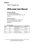
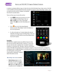
VRx-13000-8137
Installation, Operation & User Manual
September 28, 2007
TSi Power Corporation
VRx-13000-8137
VRx-13000-8137 is an AC power conditioner and precision PWM voltage regulator built
in a weather-tight, wall-mountable cabinet for protection of telecommunications, security
& remote monitoring systems in outdoor environments.
Before installation, identify the key parts of the system:
1)
2)
3)
4)
5)
6)
7)
8)
9)
10)
11)
12)
13)
IP66 rated sealed compartment
IP32 rated transformer compartment
Hot air exhaust pipes
Cold air entry pipes
AC input & Regulated AC output cable glands (water-tight construction)
Wall-mounting feet (at four corners)
7A, 7B and 7C are voltage regulating (buck-boost) transformers
Note: three transformers are connected in parallel
Main VRp-13000 precision PWM voltage regulating board assembly
Heatsink cooling fan
Surge protection & filter board
On/Off switch (AC input Circuit Breakers)
AC input & VRx output wire connectors (terminal blocks)
Green & Yellow Status Indicator LED lamps
3
1
7A
2
12
8
11
13
7B
9
5
7C
4
10
6
TSi Power Corporation
1103 West Pierce Avenue
Antigo, WI 54409, USA
Tel: 715-623-0636
Fax: 715-623-2426
1
Website: www.tsipower.com
e-mail: [email protected]
VRx-13000-8137
TSi Power Corporation
1103 West Pierce Avenue
Antigo, WI 54409, USA
Installation, Operation & User Manual
Tel: 715-623-0636
Fax: 715-623-2426
2
September 28, 2007
Website: www.tsipower.com
e-mail: [email protected]
VRx-13000-8137
Installation, Operation & User Manual
September 28, 2007
Installation & Inspection
1. Perform a visual inspection of inside & outside of cabinet. No physical damage
should be found on the metal cabinet or painted surfaces. Inspect all the parts
inside the cabinet (under bright lights) and verify that there is no broken parts or
loose wire connectors which might have occurred during transportation.
2. The cabinet can now be installed on a wall using the four mounting feet provided
at the four corners. Caution: Since the cabinet is very heavy, exercise extra
caution when lifting up or carrying the cabinet.
3. After the cabinet is firmly bolted on to a wall, bring the wire conduits carrying AC
input & regulated AC output wires and attach them to the cable glands (#5).
4. Make sure that On/Off switch and circuit breaker (#11) is in OFF position.
Connect AC input wires
Caution: Make sure that the 230 input wires are de-energized before stripping
the end of wires & connecting to the input terminals.
5. Connect 230 vac, 80A input wires to the INPUT TERMINAL (#12) pins marked as
LI, NI and G (Input Line 1, Input Neutral / Line 2 and Input Ground). Input wire
sizes must be at least 30 square mm as maximum input current could be 80A.
Connect a 200 watt light bulb (for testing)
6. Connect a 200 watt incandescent light bulb to the OUTPUT TERMINAL (#12)
pins marked as LO and NO (Output Line 1 and Output Neutral /Line 2) as a test
load.
Energize input mains 230 VAC & verify operation of VRx
7. Energize AC input circuit by turning on the 230 vac power source (and by turning
on the On/Off switch (#11).
8. After about 5 seconds, the green “Regulation OK” LED (#13) on VRp-13000
board must turn on. The 200 watt test light bulb must turn on as well.
Verify that the yellow “Bypass” LED is off after 5 seconds.
Measure AC input voltage using a DMM (digital multi-meter) across the Terminal
Block (#12) pins marked as LI and NI. Verify that input voltage is 230 vac +/25% (within 160~300 vac).
Measure VRx output voltage using a DMM (digital multi-meter) across the
Terminal Block (#12) pins marked as LO and NO. Verify that the output voltage
is 240 vac +/- 3% (233~247 vac).
TSi Power Corporation
1103 West Pierce Avenue
Antigo, WI 54409, USA
Tel: 715-623-0636
Fax: 715-623-2426
3
Website: www.tsipower.com
e-mail: [email protected]
VRx-13000-8137
Installation, Operation & User Manual
September 28, 2007
Notes: If the green LED does not turn on, it means output voltage is not being
correctly regulated. Contact factory immediately for technical support.
If the 200 watt lamp does not turn on, VRx is not functioning correctly.
Contact factory immediately for technical support.
If the yellow LED remains ON, it means system is in Bypass mode.
Contact factory immediately for technical support.
If the output voltage is outside of 233~247 vac window, then VRx is not
regulating correctly. Contact factory immediately for technical support.
9. If the VRx is operating properly, then turn off the unit by turning of the On/Off
switch (#11). Then remove the 200 watt test light bulb wires from the terminal
block (#12) LO and NO pins.
Verify VRx operation with actual load equipment
10. Connect the wires from the actual equipment to Terminal Block (#12) pins LO,
NO and G. Because maximum output current could be 60A, wires must be at
least 25 square mm.
Warning: In order to eliminate electric shock hazard when touching the metal
cabinet, good earth ground wire must be supplied to the VRx (green/yellow earth
ground wire must be connected to input G ground pin). Green/yellow earth
ground wire from the output G ground pin must also be connected to the metal
cabinet of the load equipment to ensure that the load equipment cabinet is
properly connected to earth ground.
11. You are now ready to test the performance of VRx with actual equipment load.
12. Perform steps 7 & 8 with actual load equipment load. If all green LED turns on
(and yellow LED remains off) after 5 seconds, output voltage from the VRx is
within 223~237 vac (measured with a Digital Multi-Meter) and load equipment is
operating properly, then VRx is operating properly.
Annual Preventive Maintenance Procedure
1. Visually inspect the cabinet and ensure that there is no rust or corrosion inside or
outside. Touch up with paint if rust or damage to paint is detected.
2. Vacuum or blow away all dust, dirt or dead insect build up inside the unit or
inside the hot air vent pipes (#3) cold air entry and cold air entry pipes (#4).
3. Verify that green LED is ON, yellow LED is OFF and that output voltage
measured across terminal block (#12) pins LO and NO is within 233~247 vac.
TSi Power Corporation
1103 West Pierce Avenue
Antigo, WI 54409, USA
Tel: 715-623-0636
Fax: 715-623-2426
4
Website: www.tsipower.com
e-mail: [email protected]
VRx-13000-8137
Installation, Operation & User Manual
September 28, 2007
4. Inspect the surge protection & filter board (#10) for any damaged, cracked or
discolored components. Some parts may crack or change color (brown burn
marks, etc.) if this board is subjected to high energy surges & spikes caused by
lightning strikes, etc. Board with discolored, cracked or damaged parts must be
replaced immediately.
5. Every 4 years, the heatsink cooling fan (#9) should be replaced to prevent
unexpected fan failure.
Recommended Spare Parts List
VRp-13000 board assembly (#8)
Surge Protector & Filter Board Assembly (#10)
Heatsink cooling fan (#9)
Note: Keeping about 5 to 10% (one board set for every 10~20 units) in spare boards is
highly recommended to minimize VRx repair time. Also, shipping costs (per each
repaired board) can be reduced dramatically by always shipping a group of 3 or
more boards in one box, as the cost of air shipment can be very high.
HOW TO RETURN DEFECTIVE BOARDS FOR REPAIR OR REPLACEMENT
1. Contact TSi via telephone, fax or e-mail to obtain a Return Material Authorization
number (RMA). Phone/ fax/e-mail address information is provided below.
2. Make sure that returned boards are properly protected with anti-static bubble
packs and packed in sturdy shipping box which will not be crushed when another
heavy box is placed on top of it.
3. Mark shipping box with RMA number, using indelible marker pen.
4. We recommend that DHL is used for shipments originating outside the USA and
FedEx for US domestic shipments. Do not use United Parcel Service if possible.
5. Upon receiving the part TSi will determine if it is covered by warranty—warranty
repair or replacement is performed without charge. TSi will quote repair costs for
out-of-warranty parts prior to starting any repair work. If repair is not cost
effective TSi will quote the cost of a replacement part.
6. Shipping costs, duty and brokerage costs are the responsibility of the customer.
TSi Power Corporation
1103 West Pierce Avenue
Antigo, WI 54409, USA
Tel: 715-623-0636
Fax: 715-623-2426
5
Website: www.tsipower.com
e-mail: [email protected]