1
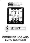
DESIGNED AND
MANUFACTURED
IN ENGLAND
7
CLIPPER
DEPTH
DEPTH
METRES
ECHO
SOUNDER
INTRODUCTION
2
INSTALLING THE DISPLAY
2
INSTALLING THE TRANSDUCER
3
NOTES ON ELECTRICAL INTERFERENCE
5
GETTING STARTED
5
OPERATIONAL CONTROLS
7
BACKLIGHT SETTING
7
CHANGING DEPTH ALARM SETTINGS
9
ACTIVATING DEPTH ALARMS
10
CHANGING THE GAIN DELAY SETTING
11
CHANGING THE UNIT’S OPERATIONAL CONFIGURATION
11
SWITCHING BETWEEN FEET AND METRES
12
CHANGING THE KEEL OFFSET
13
CHANGING BETWEEN KEEL AND SURFACE OFFSET
13
CHANGING THE DISPLAY UPDATE RATE
14
DISPLAYING AVERAGED READINGS
15
RETURNING TO NORMAL ECHO SOUNDING
16
REMOTE REPEATER FACILITY
16
INTRODUCTION
The Clipper Echosounder is supplied complete with display unit,
transducer and alarm. It is intended for 12V ship’s supply operation
although, because of its lower power consumption, it can be run
from an external dry battery.
INSTALLING THE DISPLAY
Select a convenient position for the display on a panel or bulkhead.
The site must be flat and the cavity behind the panel must remain
dry at all times. (The cable entry is deliberately not sealed to
ensure adequate ventilation. This prevents misting of the display).
Cut a hole in the panel 67mm wide and 87mm deep. Bring the
wiring through the hole in the panel and connect the black wire to
negative and red to positive. (See Figure 1). It is wise to use a fused
supply to provide protection should a fault occur. The current
consumption is very small, so a Amp fuse is more than adequate.
The red wire of the alarm bleeper is also connected to the positive
supply, as shown on Figure 1. The black wire of the alarm bleeper
connects to the green wire from the display unit. The alarm bleeper
is not watertight and must be mounted in a protected position.
FUSED
POSITIVE
SUPPLY
-
Figure 1 Echosounder and Alarm Bleeper Connections
2
Unscrew and remove the two wing nuts from the rear of the
instrument and remove the stainless steel clamping bracket. Fit
the O-ring seal into the groove in the panel mounting face of the
instrument. Ensure that it is correctly lying in its groove before
fitting the instrument to the panel, which provides the watertight
seal for the display.
Fit the instrument into the panel, fit the stainless clamp over the
studs, fit and tighten the two wing nuts finger tight only.
It is important that the O-ring rubber seal makes good contact with
the panel to prevent water getting behind the unit and entering the
cavity behind the panel.
It is good practice to run the cables vertically downwards from the
unit, even if they later have to rise to connect to the vessel's
supplies. Doing so prevents any water that might get onto the
cables from running back along the cables and into the unit.
INSTALLING THE TRANSDUCER
The transducer can be mounted in one of three ways:
(i)
The transducer face can be bonded directly to the inside of the
hull. (Some energy is lost to the hull but the loss in
performance is, for most G.R.P hulls, hardly noticeable).
(ii) A transom mount is available from your dealer.
(iii) The transducer can be'positioned inside a G.R.P. hull by
means of an In Hull Transducer Kit.
The latter method of installation offers the advantage that the
transducer can easily be removed for examination or installation
elsewhere. It should be mentioned however, that although the ,
accuracy will in no way be affected by installing the transducer
inside the hull, the maximum range sensitivity may be reduced,
5
depending on the thickness and quality of the glass fibre. The In
Hull Kit is available direct from NASA Marine or your local
chandler.
Whichever method is selected, the best location still has to be
found.
Select a position below the water level where the transducer
will point substantially vertically downwards towards the
seabed, and where the transducer and its cable (do NOT
shorten the transducer cable) will be well clear of equipment
which might be a source of interference. Such sources might
include the engine ignition and starting systems, alternators
and dynamos, electric pumps, etc. This position should also be
well clear of large masses of bubbles or cavitation near
propellers or sudden changes in hull profile which could disrupt
the signal.
To test the suitability of the location when the vessel is in the
water at a reasonable depth, press a little sticky chewing gum on
the surface of the transducer and stick it down to the inside of the
hull (it may be necessary to remove dirt and oily residue first).
The unit can then be tested over a range of speeds and depths. If
the location is satisfactory, the chewing gum must be removed
and the transducer permanently mounted using one of the
methods described previously. (Note: do NOT shorten the
transducer cable).
It is important that the face of the transducer is thoroughly bonded
down to the hull. A single air bubble will cause a considerable loss
in performance.
The transducer and the place of mounting must be kept entirely
free of any antifouling compound as this can also effect the
performance of the unit.
4
NOTES ON ELECTRICAL INTERFERENCE
External electrical interference is characterised by persistent,
random numbers on the display which obscure the true depth
reading on the depth sounder.
This is caused by large amplitude voltage “spikes” generally
associated with the engine’s alternator and/or ignition system which
has not been properly suppressed. These “spikes” may find their way
into the sensitive amplifier section of the depth sounder in two ways:
(a) Through the craft’s common power supply or
(b) Through direct radiation from the source of interference.
To reduce the possibility of induced interference from the engine’s
generator and/or ignition system, choose a position as far away
from the engine as possible and run the cable from the transducer
as far as practicable from the engine. Do NOT cut the transducer
cable, but stow excess away from any possible source of electrical
interference.
GETTING STARTED
When the Clipper Echosounder is first turned on, it automatically
performs a number of setf-test processes, and after a brief delay
switches on the backlight illumination at the factory pre-set level. It
then displays a symbol representing the keel offset (which is pre-set
in the factory to zero, as shown on Figure 2) for about one second.
Under normal circumstances, the display then almost immediately
shows the word DEPTH, and the depth below the transducer, as
shown on Figure 3. However, if the transducer has not been
connected, or no echoes are received for any other reason, the word
DEPTH is not displayed and the unit waits for another five seconds
before showing “out”. If that happens, check the connections to the
transducer, and that it has been correctly installed.
5
I
-
Figure 2 Power-Up Display
VALID DEPTH READING
DEPTH IS NOT LESS THAN
SHALLOW ALARM DEPTH
DEPTH IS NOT MORE THAN
DEEP ALARM DEPTH
DEPTH
DEPTH RATE
INDICATOR
DISPLAY IS METRES
ALARMS ARE ACTIVE
MAKE DEPTH
SHALLOWER
CHANGE BACKLIGHT
BRIGHTNESS
SWITCH TO SETTING MAKE DEPTH
GAIN DELAY
DEEPER
-
Figure 3 Normal Operating Display
When the unit is working normally as shown on Figure 3, it
shows the word DEPTH, and the depth beneath the transducer
in feet or in metres. The display is updated about twice a
second to reduce the variability of the display when there are
bubbles, turbulence, or outboard motor noise. Any such
sources of interference can affect steady readings on the
d isplay.
6
The depth rate indicators (to the right of the backlight brightness digit,
see Figure 3) are used to assist in interpretation of the bottom profile
as the vessel moves over it, or to indicate the effects of tide and swell.
The display of the depth rate is derived from averaged measurements
of depth. When the depth measurem’ent is steady (the depth is
constant), only the middle bar is lit, as shown on Figure 3. If the depth
is increasing, the right arrow-head is lit instead. Likewise, if the depth
is decreasing (it is becoming shallower) only the left arrow-head is lit.
The depth rate indicators work on an averaging time of several
seconds, and so, when the unit is first turned on, the right arrow is
lit to indicate that the unit’s estimate of the depth is increasing from
its initial value of zero. When the average value has stabilised, the
middle bar lights instead. Whenever the rate at which the depth is
changing is less than about 60 feet per minute (20 metres per
minute), the central bar is lit. When the rate is higher either the left
or right arrow-head is lit.
The depth rate indications are the only displays which cannot be
changed by the user to match the operating requirements. The
Clipper Echosounder has a number of facilities which can be
changed during normal operation to change the settings of the
backlighting, to alter the depth where swept gain begins, to change
the settings of the depth alarms, and to switch depth alarms on or
off. All these facilities are described below.
OPERATIONAL CONTROLS
BACKLIGHT SETTING
Backlighting is provided to allow the unit to be seen at night. The
backlight area is restricted in the top corners of the display to
concentrate the lighting in the areas of interest. The brightness of the
backlighting is adjusted by pressing the ILLUM button at any time
during normal echo-sounding operation. Each press of the button
increases the brightness by one in the range 0 to 7, shown by the
backlight indicator in the bottom left of the display (see Figure 4).
7
-
Figure 4 Backlight Setting
A setting of zero switches the backlighting off, and a setting of 7 is full
on. A setting of 7 is succeeded by a setting of zero, and then on again
to 1, 2, 3, etc. In common with all the other settings in the unit, the
backlight setting is stored even when the unit is switched off, so that it
returns to the chosen setting again whenever the unit is switched on.
Whenever an operational setting is made, the word SET is briefly
displayed to show it is completed before the unit returns to normal
operation, as shown in Figure 5.
-
Figure 5 Setting Acknowledgement
8
CHANGING DEPTH ALARM SETTINGS
At any time during normal operation of the unit, it is a simple matter
to set an alarm for too shallow and another alarm for too deep. To
set up the deep alarm depth (below which an alarm will sound),
press the DEEP button to show the present deep alarm setting.
The display shows the word DEEP, and the present deep alarm
depth. The factory pre-set deep alarm setting is 50 metres. Press
the DEEP button to make the deep alarm depth deeper, and the
SHALL button to make the deep alarm depth shallower.
-
Figure 6 Selecting Deep or Shallow Alarm Setting
If the SHALL button is pressed steadily, the setting reduces
continually in 1.5 foot or 0.5 metre steps. If the DEEP button is
pressed steadily, the setting increases in 1.5 foot or 0.5 metre
steps. The step size depends on whether the unit is set to measure
feet or metres.
If the deep alarm depth setting reaches 99.5m, or attempts to pass
the shallow alarm setting, it stops changing. When the desired
alarm depth is set, press SET to store the deep alarm depth
setting. The display returns to measuring depth after briefly
showing SET.
9
In the same way, pressing the SHALL button during echo-sounding
switches to setting the shallow alarm depth. The word SHALLOW
is shown, and the shallow alarm setting depth is displayed. The
factory pre-set shallow alarm depth is zero. Pressing the DEEP
button makes the alarm depth setting deeper, and pressing the
SHALL button makes the setting shallower. If an attempt is made to
increase the shallow setting below the deep alarm setting, or to
reduce it to less than zero, the settings no longer change. Press
SET to store the shallow alarm depth setting, whereupon the
display returns to measuring depth after briefly showing SET.
ACTIVATING DEPTH ALARMS
At any time, the deep and shallow alarms may be activated or deactivated together at the set levels by pressing the DEEP and
SHALL buttons together, as shown on Figure 7. When alarms are
active, a bell symbol is displayed, but is absent when alarms are
de-activated. Whenever the measured (and averaged) depth is at,
or shallower than, the shallow alarm setting, the alarm sounds, and
the word SHALLOW is shown. Whenever the measured (and
averaged) depth is at, or deeper than, the deep alarm setting, the
alarm sounds, and the word DEEP is shown.
DEPTH
-
I
Figure 7 Activating and de-Activating the Alarms
10
The alarm can be stopped either by moving the vessel so the depth is
between the settings, by altering the alarm settings themselves, or by
de-activating alarms by pressing DEEP and SHALL together again.
Each press of DEEP and SHALL together switches the alarm on or off.
CHANGING THE GAIN DELAY SETTING
The Clipper Echosounder measures the depth beneath the
transducer by timing the delay between the transmitted ultrasonic
pulse (the “ping”) and its returning echo from the bottom, The echo
from nearby objects is much stronger than from more distant
objects, and so the Clipper Echosounder has swept receiver gain
sensitivity so that weaker (more distant) echoes are detected as
reliably as those from short range. However, reflections from
nearby turbulence or bubbles may sometimes be confused with
those from the bottom. To prevent nearby reflections from being
misinterpreted, sweeping the gain can be delayed until a pre-set
depth is reached. The delay is called the sensitivity threshold, and
can be viewed at any time during normal operation by pressing the
SET button. Pressing SET again returns to normal echosounding.
The sensitivity threshold can be changed if required to minimise false
detections at short range. The factory pre-set sensitivity threshold is
zero, but it can be increased in 0.1m (0.5ft.) steps, depending on the
configuration of the unit, up to a maximum of 5m (16.5ft.). Press SET
to enable sensitivity threshold changes. The DEEP and SHALL
buttons then make the sensitivity threshold deeper and shallower
respectively within the available range. Pressing SET again to return
to normal echo-sounding also stores the revised sensitivity threshold
in memory, so the unit always operates with the new setting.
CHANGING THE UNIT’S OPERATIONAL CONFIGURATION
The Clipper Echosounder can be changed to operate in several
different ways to suit differing users’ requirements. In order that the
configuration changes are not made accidentally, changing can be
done only when the unit is switched on (powered up).
11
CHANGING THE KEEL OFFSET
The keel offset represents the distance between the transducer itself
and the bottom of the keel. When a keel offset is stored, all
measurements (including alarms) are shown as if measured from the
bottom of the keel instead of the transducer. If, for example, the bottom
of the keel is 0.4metres below the depth of the transducer in the hull,
setting the offset to 0.4m will ensure that the readings displayed show
the depth below the keel instead of from the transducer.
I
The DEEP and SHALL buttons are used separately to adjust the
keel offset value in the range 0 to 2.5m (8.3ft.), in steps of 0.1 m
(0.5ft.).No repeat is embodied on the keys because of the small
range of adjustment. Pressing DEEP increases the keel offset
depth, and pressing SHALL reduces the keel offset depth.
CHANGING BETWEEN KEEL AND SURFACE OFFSET
It is sometimes preferable to measure the depth from the surface
instead of the transducer or keel. If, for example, the transducer is
0.3m below the surface, setting a surface offset of 0.3m will ensure
that the readings displayed show the depth below the surface
instead of from the transducer itself. Pressing the SET and DEEP
buttons together switches between the keel depth and surface
depth measurement modes, as shown on Figure 9.
DEPTH BELOW SURFACE
DEPTH BELOW KEEL
-
Figure 9 Switching Between Surface and Keel Depth.
13
Pressing them together again switches the setting back again. The
bar represents the position in relation to the hull-mounted
transducer (represented by the “U”) from where the measurements
are made. Whichever mode is chosen, all measurements, including
alarms, use the same reference point - that is, the surface or the
bottom of the keel - ‘depending on the setting chosen.
CHANGING THE DISPLAY UPDATE RATE
The Clipper Echosounder sends ultrasonic “pings” at a rate of
about seven per second. The rate of pinging is limited by the
maximum depth capability of the unit (100m). A new measurement
of depth is thus available within the unit seven times a second. In
turbulent conditions, or in the presence of high levels of noise such
as outboard motors, there can be rapid variations in the measured
depth. These rapid changes can be confusing if they are displayed,
and so the unit can be adjusted to have a display update rate which
is slower than the ultrasonic ping rate.
The update rate can be set to change on every ping (reading 1), every
second ping (2), every third ping (3),and so on up to every seventh
ping (7). If set to update every seventh ping, the display update rate is
about once per second. The factory pre-set update rate is every third
ping, which updates the display approximately twice a second.
-
Figure 10 Changing the Display Update Rate
14
Press SET and SHALL together to increase the update rate by one,
as shown on Figure 10. The resulting setting is shown on the digit
in the left-hand bottom corner, and changes successively from the
factory pre-set value of 3 to 4, then to 5, to 6 , to 7, and then on to
1, 2, etc. for every successive press of SET and SHALL together.
The last setting chosen is stored.
DISPLAYING AVERAGED READINGS
The unit averages the depth readings it makes seven times a
second with an averaging time of about two seconds. The
averaged values reduce the effect of swell and turbulence on the
readings, but the accuracy of readings is not compromised. The
averaged, rather than the instantaneous, values are used
internally by the unit to trigger the alarms. Using the slow-moving
averaged values prevents triggering false depth alarms if
interference is present, by ensuring that the alarm depth has
been consistently crossed before the alarm is sounded.
The factory pre-set display mode is Fast (F), which shows depths
as they are received twice a second. Press DEEP and SHALL
together to switch between Fast (F) and Averaged (A) depth
display. The present display status is shown on the digit in the lefthand bottom corner, which switches between F and A for each
press of DEEP and SHALL together, as shown on Figure 11.
Use of Averaged readings results in very smooth changes in the
displayed readings, and greatly reduces the unit’s sensitivity to
external noise and turbulence. Note that using averaged
readings is not the same as setting a slow update rate.
Averaged readings change relatively slowly, but the display rate
determines how often the readings (averaged or fast) are
displayed. It is a matter of operational choice of where to strike a
compromise between display rate and fast or averaged
measurements.
15
-
Figure 11 Switching Between Averaged and Fast Display Modes
RETURNING TO NORMAL ECHOSOUNDING
Press the ILLUM button to return to normal echo sounding at any
stage. All the settings are stored, and will return again whenever
the unit is switched on. Returning to configuration setting from
normal echo sounding is not available. If further configuration
changes are desired, they can be made only by switching the unit
off and then on again with ILLUM pressed during the start-up
time, as described above.
REMOTE REPEATER FACILITY
A repeating display unit is available for use with the Clipper
Echosounder. The repeater cable is plugged into the rear of the
master instrument. The repeater socket is exposed by pulling off
the round cover on the rear of the instrument. If no repeater is to
be connected, leave the cover in place.
16