1
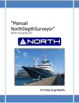
Naviguer D Sounder User Guide North Group LTD. NAVIGUER D ECHOSOUNDER Naviguer D Sounder User Guide 1 www.northsurveying.com Naviguer D Sounder User Guide Index. Introduction. ....................................................................................................................................... 4 Warning. .............................................................................................................................................. 4 Specifications ...................................................................................................................................... 4 System Requirements ......................................................................................................................... 5 Features............................................................................................................................................... 5 Installation........................................................................................................................................... 6 Mounting and Wiring. ..................................................................................................................... 6 Transducer Installation.................................................................................................................... 6 Operation. ........................................................................................................................................... 8 Operator’s Console.............................................................................................................................. 9 Right Click Screen Settings. ............................................................................................................... 10 Right Click on the Color Bars. ............................................................................................................ 11 Drop-Down Menus. ........................................................................................................................... 11 File Menu....................................................................................................................................... 11 Options Menu. .................................................................................................................................. 12 View Menu. ................................................................................................................................... 14 Help Menu. .................................................................................................................................... 14 Console Settings and Their Effects. ................................................................................................... 14 Full/Split Screen. ........................................................................................................................... 14 Manual/Auto Mode. ..................................................................................................................... 14 Sound ON/OFF............................................................................................................................... 15 Clutter Filter. ................................................................................................................................. 15 Noise Filter. ................................................................................................................................... 15 North Group LTD. Chart Speed. .................................................................................................................................. 16 Transmitter Power. ....................................................................................................................... 16 Display Threshold. ......................................................................................................................... 16 AScope Threshold.......................................................................................................................... 17 Cursor Position. ............................................................................................................................. 17 Mode. ............................................................................................................................................ 17 Date and Time. .............................................................................................................................. 17 2 Naviguer D Sounder User Guide Latitude and Longitude. ................................................................................................................ 17 Pause and Clear. ............................................................................................................................ 18 Screen Settings and Their Effects. ..................................................................................................... 18 Frequency. ..................................................................................................................................... 18 A-Scope. ........................................................................................................................................ 19 Signal Processing Type. ................................................................................................................. 19 Depth Range. ................................................................................................................................. 20 Depth Offset and Zoom. ................................................................................................................ 21 Import Data From / Export Data To. ............................................................................................. 21 Manual Settings................................................................................................................................. 21 NMEA 0183 Output. .......................................................................................................................... 22 North Group LTD. Hints and Suggestions for Settings. ................................................................................................... 22 3 Naviguer D Sounder User Guide Introduction. The Naviguer D is a 50/200Khz color Echosounder with sea water temperature and full/split screen capability that works in both standard analog mode and DSP (Digital Signal Processing) modes to extend the sensitivity and depth range. The standard package is supplied with a low-profile plastic thru-hull transducer. Two different bronze thru-hull and a plastic transom mount transducer options are available. The Naviguer D Echosounder software is easy to learn and uses an intuitive Windows interface with drop down menus and mouse control. All settings and control values such as transmit power, pulse width, depth/temperature units, zoom modes, etc. can be saved to named setup files for immediate future use. With a few clicks of the mouse you can recall your favorite settings for different areas or create entirely new settings. Warning. Sonar pulses are affected by numerous naturally occurring phenomenon such as currents, thermal layers, double and triple bounce, turbulence and varying bottom conditions. While we make every attempt to try to insure that the digital depth number displayed on the screen is correct you should use this number only as one navigational input and not rely totally on the displayed number. The settings you use for transmit power, gain, etc. all affect the reliability of the displayed depth value and you should use other navigational aids such as charts and GPS position to insure that you navigate your vessel safely. Specifications - Operating Voltage: 9.5 to 16.0 VDC, 0.05 amps nominal, 4.7 amps peak at max power North Group LTD. - Indicator: Front panel LED for Power ON/Off and communications indicator. - Output Power: 2560 watts peak-to-peak (320W RMS). 24KW DSP processed power (3200 WRMS) - Depth Capability: 1000 Feet (304 meters) or more at 200kHz 1500 Feet (457 meters) or more at 50kHz 4 Naviguer D Sounder User Guide - Operating temperature: 0 to 50 deg Celsius ( 32 to 122 deg Fahrenheit). - Transducer: Dual Frequency 50/200kHz, Depth/Temperature System Requirements WIN98 SE, 2000, XP, Vista and 7 500 Mhz Pentium PC (or better) Serial Port (16550 compatible UART) and/or USB port 128MB RAM 50MB Hard Drive space SVGA Graphics (1024 x 768 resolution) Mouse / Keyboard North Group LTD. Features High resolution Color 200kHz, 50Khz and water temperature GPS Latitude, Longitude and Ground Speed display Auto and Manual controls for depth, gain, transmit power, etc. Full or Split screen Six different depth ZOOM settings Record/Playback to/from log files A-Scope (analog return signal strength) Gray Line White Line STD (standard display) STD/BTM (standard bottom lock) Six Depth Ranges Six Depth Offsets (shifts) Manual & Auto Depth Shift 8 Selectable Chart Speeds 10 Selectable Noise filter settings 8 Selectable Clutter settings 5 Selectable Intensity Color pallets 5 Selectable background colors Feet, Meter, Fathoms selection 5 Naviguer D Sounder User Guide Degrees F and Degrees C Temperature selection Simple On-screen Temperature calibration "Speed-of-Sound" adjustement for salt/fresh water & user defined Deep and Shallow water alarms Four types of Intelligent alarms Anchor Drag alarm Both RS-232 Serial and USB communications interface built-in Adjustable Transmitter power and Adjustable Receiver Gain Digital Cursor Readouts (Full and Split screens) Analog and DSP (Digital Signal Processing) control Depth Dependent Gain control DEMO (Playback) Mode Built-in thermal shut-down protection Built-in self test functions Built-in POWER/communication activity LED Installation. Mounting and Wiring. The Echosounder should be located in a dry area in where the temperature does not exceed 50 deg C (120 deg F). The transducer comes supplied with a 6 pin Conexal female connector that plugs into the 6 pin male Conexal connector on the Echosounder. North Group LTD. Transducer Installation Plastic housings are recommended for fiberglass or metal hulls. Never install a plastic Thru-Hull housing into a wooden boat hull. The swelling of the wood may cause a fracture to occur. Bronze housings are recommended for wood or fiberglass hulls. Never install a bronze housing in a metal hull, because electrolytic corrosion can occur. Stainless steel housings are recommended for metal hulls to prevent electrolytic corrosion from occurring. Never install a metal housing in a hull with a positive ground. The transducer supplied for use with the Naviguer D Echosounder is a dual frequency 50/200Khz depth and temperature transducer. The use any other transducer other than that expressly supplied with the Echosounder will void the warranty and can result in damage to the device. The transducers contain a crystal element and care should be taken in handling the transducer so as not to damage the sensitive transducer face. You should 6 Naviguer D Sounder User Guide not coat the transducer face with antifouling paint. Mounting the transducer inside the boat to “shoot through the hull” will result in less than optimal performance and the use of an adhesive such as epoxy, glue, silicon adhesive or bedding compound will void the transducer warranty. A low profile plastic thru-hull transducer is supplied as standard with the Naviguer D software. Two different bronze thru-hull transducers or a transom mount transducer are available as options. The following instructions are for installation of the plastic thru-hull transducer. Please see the separate installation instructions provided with the other transducer options for the correct installation of those units. The transducer should be located in an area of the boat hull that is free from turbulence caused by thru-hulls, paddle wheels or any other obstructions. It is important that the water flowing by the transducer face be free of air bubbles caused by turbulence. If the hull is not parallel to the water, then a suitable fairing block should be used to insure that the transducer is mounter perpendicular to the sea bottom. On sailboats the transducer should not be located too close to the keel. In routing the cable to the Echosounder, avoid placing it near or parallel to other electrical cables, particularly ignition and alternator wiring. Use care when routing the cable through bulkheads and other parts of the vessel to avoid tearing the cable jacket thus exposing it to the harsh environment. Acoustic noise is another item to take into consideration when determining a location of the transducer. Vessel generated noise from the propellers, shafts and other machinery should be avoided also. After determining the best location from the outside, consider the need for room inside the hull to tighten the mounting nut and the need to route the transducer cable away from other electrical noise generating wires. North Group LTD. Once a location has been determined, and prior to drilling any holes in the hull. Inspect the location from the inside of the hole to ensure that the location you have chosen will not interfere with any bulkheads, plumbing or any other obstruction. 1. Drill a small hole first from the inside of the hull at the desired location for the transducer. This will be a locating hole for the final drilling. 2. From the outside, enlarge the locating hole to ¼” or whatever size necessary for the pilot drill of the 2” hole saw. Drill the pilot hole vertically, followed by the hole saw. 3. After drilling, remove any rough edges around the hole and thoroughly clean and sand the inside and outside surfaces around the hole. 4. Remove the wing nut from the transducer housing. Apply a generous amount, approximately 1/16” thick, of a good marine adhesive/sealing compound around the lip of the housing that contacts the hull. The compound should also extend up the sidewall of the housing, ¼” higher that the combined thickness of the hull and wing nut. This will 7 Naviguer D Sounder User Guide ensure there is sealant in the threads to seal the hull and to hold the wing nut securely in place. 5. From the outside of the hull, insert the transducer housing and gently rotate the housing to squeeze out any excess sealant. 6. From the inside, thread down the wing nut until it makes contact with either the hull or fairing block, if used. The wing nut should then be tightened to a snug fit, hand tighten only. DO NOT OVERTIGHTEN THE WING NUT. Note: For a cored fiberglass hull, thru hull transducer installation should only be performed by a trained technician. Improper sealing of the core material can lead to premature failure or possible water leakage. Operation. Initial Installation For easy access to the program, Click the “Start”, “Programs” buttons and use the mouse to navigate to the “Naviguer D” program listing or double click the icon to launch the Naviguer D program. North Group LTD. The first time you start the program it will display the Interface Box Communications Port selection menu: Be sure that the all deice is attached to your PC and that +12VDC power has been turned on. Select the COM port where the Echosounder is attached and click on “Accept”. If you do not have a Echosounder attached (to run the software in demo mode and/or to playback some prerecorded files), select “None” and click on the “Accept” box. The program will then ask for a (optional) GPS COM input port and a serial COM port to use to output NMEA data of the depth, water temperature and GPS data (see NMEA Output Sentences in this user’s manual). Select “None” if these are not going to be used at this time. 8 Naviguer D Sounder User Guide The program will communicate with the Echosounder on the COM port you specify and the following default screen is displayed: North Group LTD. Operator’s Console The main Operator’s Console (shown on the last Page) allows for immediate control of a number of important functions with a click or two of the mouse: Pause/Run the Echosounder hardware Clear the display screen of all previous data Select Full or Split screen operation Select Automatic or Manual operation mode Enable or Disable the alarm sound (On/Off) Select the desired level of Surface Clutter filtering Select the desired value of Noise Filtering Adjust the Chart Speed Adjust the transmitter Power Access a number of Drop-Down menus Additionally you can right-click in the data display area to bring up further menu screens or right click on the Color Bar to access other color schemes for the data. In order - this user’s manual will first discuss the data screen right-click options, the right click Color Bars options and then the drop-down menu items in turn. 9 Naviguer D Sounder User Guide Right Click Screen Settings. If you right-click the mouse button with the mouse positioned in the data area of the display screen a “Screen Settings” menu will appear. Clicking on the “Full” screen will bring up the “Full Screen Settings” menu. If the display is in split screen mode, then right-clicking the mouse when the mouse pointer is located in the right-hand of the split screen will result in the “Right Screen Settings” menu being displayed. Right-clicking the mouse when the mouse cursor is on the left side of the split screen display will result in the “Left Screen Settings” menu being shown. The three screen menus are very similar except control only those features of their respective Full, Left or Right screens. Changing a control with the Right Screen Settings menu will not affect the Left Screen Setting or Full Screen Setting values. The Screen Settings menu will stay on top of the data screen until you close it or click elsewhere outside of the Screen Settings menu box. The Screen Settings menu lets you change many of the operations of the Echosounder. You can change the operating frequency, type of signal processing used by the Echosounder, zoom to a range of interest by changing the range and depth offset of the displayed data and control the transmitter pulse width and receiver gain. North Group LTD. Any changes made with on the Screen Settings menu affect only the screen being adjusted - not the other screens. This provide for total flexibility in that different settings can be programmed for each screen. For example, you can program the Echosounder to use different transmitter pulse widths for the Full, Left and Right display screens. There is an option to export all of the setting from one display screen to another display screen. If you like the way the right hand side of the split screen display looks and want the Full screen to have the same settings, you can export all the Display Settings from the Right Screen to the full screen with a click of the mouse. You can also import all the Screen Settings from another screen to the current screen the same way. The individual setting of the Screen Settings menu and their meanings and effects are explained in the “Screen Settings and Their Effects” sections of this manual. 10 Naviguer D Sounder User Guide Right Click on the Color Bars. When you right click on the color bars, the Color Bars selection and editing menu appears. You can select from four different predefined color schemes to represent the received signal strength or define your own. Up to 16 colors can be defined in the User Defined color bar. The color bar selection and User Defined colors are automatically saved to a setup file when you exit the program, if desired. Also see “Display Threshold” for further information about the color bar. Drop-Down Menus. You can access a number of drop-down menus from the main operator’s console by clicking the mouse on the “File”, “Options”, “View” and “Help” menus at the top-left of the screen. File Menu. The “New” selection will create a display with all “factory” defaults for the settings. The “Open Settings” selection creates a display with the same settings as saved previously using the “Save Settings As” menu selection. North Group LTD. The “Save Settings” command will save the current settings to a file. This file is automatically loaded the next time the program starts. The “Save Settings” and the “Save Settings As” commands save all the current settings for all three display screens (Full, Left and Right) and all the current Operator Console settings such as transmit power, noise filter settings, alarm values, units of measure, color bars, etc. The “Save Settings” and “Save Settings As” commands are not the same as the “factory default” settings which is selected only with the “New” command. The “Save Settings As” command is used to save the current settings with a name you want to give the current settings. With this command you can create a library of favorite screen settings for each area you visit, then recall those setting at any time by using the 11 Naviguer D Sounder User Guide “Open Settings” command. In deep water you might want to have settings that use higher power, a wider transmitter pulse width using 50Khz and display data with a deeper Depth Range than the settings used in shallow water. You can save the deep water settings with a name called “Deep” and have a settings file called “Shallow” for shallow water and another called “Marina” to set up the Echosounder especially for entering or leaving your marina. Options Menu. The Options Menu items are used to select Units of Measure, Set Alarms, select screen colors and turn ON or OFF features such as recording or playing of data log files. North Group LTD. The selection of some of these menu items will result in submenus being displayed or entire new windows in order to select view or set the desired values. 12 North Group LTD. Naviguer D Sounder User Guide 13 Naviguer D Sounder User Guide View Menu. The View Menu is used to select what you want to see displayed on the Operator’s Console. Items can be individually turned ON or OFF with the click of the mouse. Help Menu. The Help menu is used to display some help text and details about the Naviguer D program and Interface Box. If you find it necessary to email for help, please include the details from the “About” box as well as your system and Windows software version being used. Console Settings and Their Effects. This section discusses some of the various Echosounder Operator’s Console settings, their options and some of the effects they have on the operation. Full/Split Screen. Selecting Full Screen results in the entire display width being used to display data from a single frequency - either 200kHz or 50Khz. Selecting Split Screen causes the display screen to be split in two halves – the Left Screen and the Right Screen. In split screen mode you have complete control over how each of the two screens displays data. You can display data for the same frequency (200kHz or 50Khz) in two different ways or display data for both the 50Khz and 200Khz frequencies simultaneously. There are three separate sets of screen settings: “Full Screen Settings”, “Left Screen Settings” and “Right Screen Settings”. For more details, see the “Screen Settings and Their Effects” section of this manual. North Group LTD. Manual/Auto Mode. Selecting Manual Mode puts the Echosounder into a mode where you can control each of the parameters such as Transmitter Power or Receiver Gain and Depth Range manually. This gives you complete control and flexibility of how the Echosounder operates. In Auto Mode the Naviguer D will attempt to set the transmitter power, depth range, receiver gain and transmitter pulse width automatically. 14 Naviguer D Sounder User Guide As the depth of the bottom varies the Naviguer D will automatically change the Depth Range to keep the bottom return on the display and adjust the power settings for the best picture. Sometimes the settings that produce the best picture of the bottom will not be the settings that result in the best display in more shallow water and you will want to control the settings yourself in manual mode. Sound ON/OFF. You can enable and disable the alarm sounds for the Shallow, Deep and Anchor Drag alarms all at one time by turning off the sound with the Sound ON/OFF feature. This prevents you from having to turn off each alarm separately using the Options pull down menu multiple times. Even with the sound turned OFF the alarm warnings will still be flashed visually on the left side of the display screen just above the digital depth number (but only if the individual alarms are enabled with the Options menu). Clutter Filter. North Group LTD. Bubbles and other debris as well as turbulence created by boat wakes and strong currents near the surface will create strong sonar returns often referred to as “Surface Clutter”. The effects of surface clutter can be distracting. The Clutter Filter is used to reduce or eliminate the effects of surface clutter. The higher the setting, the less surface clutter will show up on the display screen. The surface clutter filter will not change, reduce or eliminate the signals from the bottom or, noise or from fish (unless the object is located very close to - or in the surface clutter). Noise Filter. Small bubbles deeper in the water, acoustic noise due to engine vibrations, “transducer slap” at high boat speeds and other electrical noise can create real or “ghost” signals that can often be reduced or eliminated altogether by using the Noise Filter. The higher the setting, the more effective the filtering is. Warning - too high a setting can affect the returns from object. 15 Naviguer D Sounder User Guide Chart Speed. The rate at which the screen is updated with new information can be controlled with the Chart Speed setting. The higher the setting, the faster the data scrolls across the screen. In deep water the maximum chart speed will be reduced automatically because it takes a minimum amount of time for the sonar pulse to reach the bottom and return back to the depth transducer. For example, at a bottom depth of 1000 feet it takes about 1/2 second for the sonar pulse to travel to the bottom and back up to the transducer so if you set the depth range at 1000 feet the maximum chart speed is about two updates per second. Transmitter Power. The Echosounder contains a dual frequency sonar transmitter whose output strength can be controlled by software in 256 steps to output a signal from 0 watts to 2560 watts peakto-peak (320 watts RMS). In manual mode the Transmitter Power selection is used to set the transmitter power. Using too much power can cause the depth algorithm to become confused, however, so be forewarned that the digital number at the bottom left hand side of the display can be wrong if too much (or too little) power is used. The usual rule of thumb is to increase the power level and/or receiver gain until you can just start to see a “double bounce”. A double bounce is where you see a second return from the bottom at twice the actual depth. This is due to the sonar signal traveling back to the surface and being reflected again back to the bottom and back to the depth transducer a second time. In shallow water with hard bottoms having good reflectivity it is often possible to see second, third and even fourth bounces if too much power is used. North Group LTD. Display Threshold. The Color Bar is divided into 16 parts. The lower part has the value of 1 and the top part has the value of 16. The acoustic signal is digitized to a value from 1 to 16. When a screen pixel representing an acoustic signal is painted onto the display screen it is painted in the color representing the signal strength. A very weak signal might be painted in dark blue, a stronger signal in green and a very strong signal in red. There are a number of predefined color bars and you can also create your own color bar with colors of your choice. The Display Threshold slider determines whether a signal response gets drawn on the display screen or is ignored. If the strength of the signal is greater than the display threshold it is painted on the display screen in the color determined by the Color Bar. If the signal of that particular pixel of data is weaker than the Display Threshold then that pixel is ignored and not drawn on the display screen. 16 Naviguer D Sounder User Guide AScope Threshold. TheAScopeThreshold slider determines whether a signal response gets drawn in the AScope area of the screen (if the AScope is turned ON) or is ignored. If the strength of the signal is greater than the AScope threshold it is painted in the AScope area in the color determined by the Color Bar. If the signal of that particular pixel of data is weaker than the AScope Threshold then that pixel is ignored and not drawn on the AScope. Cursor Position. Whenever the mouse cursor is located on the data display area, the depth of the cursor is displayed in the Cursor box near the right-bottom of the screen. In split screen mode, the correct depth is displayed in the Cursor box even if the two sides of the split screen have different depth ranges and depth offsets (zoomed to different depth scales). Mode. The Mode display shows what the Naviguer D display is showing at the moment. The possible options are “Paused”, “Play” and “Normal”. Date and Time. North Group LTD. The current Date and Time (of the computer clock) will be displayed in these two boxes unless you are playing back a prerecorded log file, in which case the Date and Time the data was recorded to file will be displayed instead. Latitude and Longitude. If a GPS is connected and a valid position fix is available to the echosounder, then the current Latitude and Longitude will be displayed in these two boxes unless you are playing 17 Naviguer D Sounder User Guide back a prerecorded log file. If you are playing back a prerecorded logfile then the Latitude and Longitude of the recorded data will be displayed instead. Pause and Clear. You can click on the “Pause” box to stop the Echosounder from updating the display screen (freeze the display) in either run mode or playback mode. Clicking on the “Clear” box will clear all the signal return data from the display. Screen Settings and Their Effects. When you right click the mouse while the mouse cursor is located on the data display area, the “Full Screen Settings”, “Left Screen Settings” or “Right Screen Settings” menu is displayed, depending on where you click and whether the screen is in full or split mode. Frequency. North Group LTD. You can select 200 or 50 Khz. The use of 200kHz will provide you a more detailed display of the sonar information and will show smaller bait fish than can be detected by using 50kHz. The selection of 50kHz will show data for a larger area because the beam pattern of the 50Khz signal is much wider (45 degrees) than the beam pattern of the 200 Khz transducer (11 degrees). 50 Khz is attenuated less by water, however, and will allow you to see deeper than you can using 200Khz. A fish has to be bigger to show up at a frequency of 50khz. Often professional fishermen will use 200 Khz on one side of the display and simultaneously display the results of the 50Khz sonar signal on the other side of the display. 18 Naviguer D Sounder User Guide A-Scope. Whereas the sonar display screen shows a time history of the sonar signal, the “A-Scope” region shows the instantaneous amplitude (strength) of the sonar signal currently under the depth transducer. You can turn on an A-Scope region for the “Full”, “Left” and/or “Right” hand side of the display screen using the “A-Scope” control. The color and width of the display in the A-Scope area show the depth and strength of the signal under the transducer. The wider the line in the A-Scope the stronger the signal. North Group LTD. Signal Processing Type. You can select from four different methods to process the returned sonar signal. Each method has its advantages and disadvantages. “Analog Fixed Gain” is the easiest to understand and means that the receiver gain is fixed at one value for the entire time that the return signal is processed and painted on the display screen. 19 Naviguer D Sounder User Guide Analog Time-Varying Gain means that the receiver gain is varied as a function of time so that signals being received from deeper objects (coming back at a later time) are given more weighting. Since deeper objects usually return a weaker signal the extra gain will cause deeper objects to appear bigger or stronger. By carefully selecting the Time Varying Gain values you can make a 18 inch object appear to have the same strength (color) irregardless of the depth. When you select Analog Time-Varying Gain you will be asked to provide two different gain values - the start gain (gain at the surface) and he rate of change of the gain (how fast you want the signal gain to increase). Selecting these two values is a function of trial and error until you find settings that work for your particular situation. Remember, once you find settings that works well for you, you can save those setting with a name and load them back any time. Digital signal processing (DSP) enables the Naviguer D to go deeper and see smaller objects without increasing the power normally required to do so. The penalty you pay for using DSP is that the resolution is not as good in shallow water. Use the DSP modes only in deeper water where the analog modes no longer provide a strong enough signal return to work properly. Each of the two DSP modes Type 1 and Type 2 provide different advantages. Digital Processor Mode 2 offers the highest level of signal improvement but works on a “probability” process which results in the signal strength fading in and out. Digital Processor Mode 1 offers less signal strength improvement but provides for a more constant signal without as much signal fade as Digital Processor Mode 2. Depth Range. North Group LTD. The Depth Range value sets the depth scale from the top of the display to the bottom of the display. A selection of 100 feet will result in a depth range of 100 feet from the top of the display to the bottom of the display. This does not mean that the top of the display will be zero and that the bottom of the display will be 100 feet because the Depth Offset will affect these settings. For example with the Depth Range set to 100 feet and the Depth Offset set to 250 feet the top of the display will be at 250 feet and the bottom of the display will be at 350 feet (a Depth Range of 100 feet). 20 Naviguer D Sounder User Guide Depth Offset and Zoom. As discussed in the previous section on Depth Range, The Depth Offset is the depth value that you want displayed at the top of the screen. The Depth Offset in conjunction with the Depth Range allow you to “Zoom” the display to any given range. For example, you could show a 30 foot band from 150 to 180 feet by setting the Depth Offset at 150 feet and the Depth Range at 30 feet as shown in the picture on the right. Import Data From / Export Data To. All the screen settings discussed so far in this section on “Screen Settings and Their Effects” can be copied between the Full, Left and Right screens using the “Import” and “Export” commands. When you Import or Export the settings between screens all the settings for Frequency, A-Scope, Signal Processing Type, Depth Range, Depth Offset, and the other manual settings associated with these values are transferred together at the same time. Manual Settings. North Group LTD. Each of the four Signal Processing types have associated with them some further values that you can control in manual mode. When you select Analog Fixed Gain you must also supply the Transmit Pulse Width and the Fixed Analog Gain value to use for the transmit pulse and receiver gain. The Transmit Pulse Width sets the length of the transmit pulse. A shorter pulse provides more resolution and helps prevent small objects from blurring together but longer pulses will often provide more depth range in deeper water. In Analog Time-Varying Gain mode you must supply three different values as already mentioned earlier - The Transmit pulse Width, Surface Gain and the gain Change Rate. Basically the Surface Gain is the value of gain to start the receiver with and the Change Rate is a measure of how fast you want the gain to increase as a function of time. 21 Naviguer D Sounder User Guide In DSP mode, selecting Digital Processor Type 1 or Digital Processor Type 2 will result in your having to supply only a single DSP Gain value. The Transmit Pulse Width is automatically set by the Interface Box depending on the selected DSP gain value and you have no control over the transmit pulse width. The larger the DSP gain, the more digital processing is applied to the received signal and weaker signals can be recovered from the noisy return signal. The benefit is that you can see objects in deeper water than using analog processing. The higher DSP gains require wider transmit pulses which result in a loss of resolution in more shallow water. NMEA 0183 Output. The software can be told to turn ON NMEA 0183 serial data output from the “Options” menu <--> Serial Data Out ON/OFF. When “ON” is selected the program will send the depth, sea water temperature and GPS position and ground speed data out to a serial port (or USB port) of your choice. A sample of the data sent to the output port is shown here: $GPRMC,040113,A,3653.10,S,17437.47,E,000.6,074.4,190903,,*03 $SDDBT,015.7,f,004.8,M,002.6,F*0D $SDDPT,004.8,*75 $SDMTW,023.8,C*3D Hints and Suggestions for Settings. North Group LTD. The transmit power, receiver gain, pulse width, and signal processing type etc. all affect how the display will look and how well the unit functions as a depth Echosounder. If you are not already familiar with the adjustments we suggest that you start with the following settings and then experiment with the settings to suit your preferences: 1) Processing type - Analog Fixed Gain (not DSP or time-varying gain). 2) Receiver gain - 240 3) Transmit pulse width - 3 4) Frequency 200 Khz 5) Transmit power - 500 watts 22 Naviguer D Sounder User Guide 6) Noise filter - 4 7) Display threshold – 4 Do not switch to automatic mode until the unit has locked onto the bottom. The settings above should work well between a depth of 3-4M (10 feet) to 50M (150 feet). In deeper water you will want to increase the output power to compensate for the weaker signal levels. The general rule of thumb for stable depth numbers is to increase the output power and the receiver gain until you just BARELY start to see a double bounce signal (i.e. if you are in 20M of water you will see a double bounce signal at 40M). When you are happy with the settings for a particular situation (such as when returning to your marina slip) you should save the settings with a easy to remember name such as Returning_To_Marina_Slip. Then with a few clicks you can almost instantly recall the best settings for the location or what you were doing. The display and digital depth number can be affected by air bubbles in the water near the surface (called “surface clutter”). Surface clutter can be caused by crossing the wake of another boat, propeller wash caused by reversing or passing near objects such as bridge abutments or pilings when a current is running. There are several ways to help adjust for surface clutter. You can increase the surface clutter rejection setting and/or use time varying gain. Time varying gain allows you to select a low gain initially at the surface and then allow the gain to increase as a function of time (depth). If you use time-varying gain be sure that you still use enough gain to see the bottom or the digital depth number will become unstable. This will not be a problem in deeper water since the gain will be higher. Everything is a trade-off. You could use time-varying gain on one side of a split screen and Fixed Analog Gain on the other side to help compensate. North Group LTD. In split-screen mode the Naviguer D uses the screen that is set to see the deepest when calculating the bottom depth. Use DSP processing in very deep water when the bottom return signals are too weak to see using analog mode. DSP mode 2 gives the cleanest looking display but DSP mode 1 will allow you to lock onto the deepest bottom. The ultimate deep water response will be using DSP mode 1 with white line turned ON. In this mode the Naviguer D will work to about 3000 feet (1000M). DSP will also allow sound in deeper water than either of the analog modes. 23 Naviguer D Sounder User Guide Information/Sales: [email protected] Technical Support: North Group LTD. [email protected] Copyright 2007-2012 North. © 2007 North Group LTD. All rights reserved. 24 Naviguer D Sounder User Guide North Group LTD. NAVIGUER D ECHOSOUNDER www.northsurveying.com 25 Systems, colors and specification may vary without previous notice, for updates please refer to our website.