1
JB-304
Villa Video Door Entry System
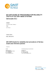
User’s Manual (V3.0)
Please read this manual carefully before the products are installed. Technical specifications
and contents are subject to change accordingly without advance notification.
CONTENTS
Page
Part 1. Product introduction
1~2
1.1 Use purpose
1
1.2 System configuration
1
1.3 Features and functions
2
Part 2. Technical parameters & structure
3~4
2.1 Technical parameters
3
2.2 Structure
3
Part 3. Installation and connection
5~11
3.1 Installation
5
3.2 Connection
7
Part 4. System programming
12~15
4.1 Audio jumper
12
4.2 Video resistor
12
4.3 Door station address
12
4.4 Card reader(for Model No.15&No.18 only)
13
4.5 Password (for Model No.18 only)
14
Part 5. Operation
16~19
5.1 Operation on door stations
16
5.2 Operation on indoor phones
16
Part 6. Troubleshooting
20
6.1 Test
20
6.2 Troubleshooting
20
Part 1. Product introduction
1.1 Use purpose
The system is applied to single family houses, offices, shops, warehouses, and other access control
purpose.
1.2 System configuration
Configuration
Options
Remarks
Door station
Model No. 6
Model No.9
Model No.15
Model No.18
①All panels are aluminum.
②Door stations don't require any direct power supply.
③Card reader is available on Model No.15 and No.18.
④Model No.9 door station is with a pinhole camera.
⑤Name tag is available on Model No.9 and No.15.
⑥There are options of the bracket (surface mount) and installation box
(flush mount) for Model No.6 and No.15 door panels.
⑦Model No.18 is with a keypad for PIN codes to release doors.
Indoor phone
Model: F-7
Model: V-26
Model: N60
Model: N72B
Model: N75B
①
②
③
④
Power supply
Adapter (18VDC, 1A)
Transformer (18VDC, 2.2A)
①Both are free voltage input AC100V~240V.
②One transformer can support up to 4 video indoor phones while one
adapter can support only one video indoor phone. But if there are 3 or
more door stations, another transformer may be required.
Model V-26: 4 or 4.3" TFT color screen.
Model N60, N72B, and N75B: 7" TFT color screen.
Model F-7: Audio handsfree indoor phone. For economic purpose.
Every video indoor phone requires the 18VDC power.
! We may provide more options and the current options may be replaced without advanced notification.
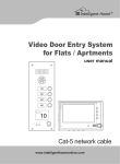
1.2.1 Door stations
CALL
MI C
Model No.6
94X138X38(mm)
Model No.9
54.5X140.5X40(mm)
Model No.15A surface mount
79X148X45(mm)
Model No.15B surface mount,
card reader. 79X148X45(mm)
Model No.18
102X175X39(mm)
Model No.15C flush mount
93X168X52(mm)
u
Model No.15D flush mount,
card reader. 93X168X52(mm)
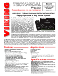
1.2.2 Indoor phones
Model F-7
101X135X25(mm)
Model V-26
180X115X21(mm)
Model N60
239X139X20(mm)
Model N72B
210X150X23(mm)
Model N75B
210X150X23(mm)
1.2.3 Power supply
Adapter
Transformer
(DIN Rail)
1.3 Features and functions
> Call, answer, and release doors.
> DIY system with 4 wires; PLUG & PLAY connection.
> Various flexible connection diagrams are optional.
> Max. capacity: Up to 4 door stations and 4 indoor phones.
> Intercom and calling transfer between indoor phones.
> Various melody ring tones are optional.
> Two options to release doors, by SIGNAL or by POWER (Models except No.9).
> Use two group passwords to release two doors and gates(Model No.18).
> Double unlock buttons to release two doors/gates/garages...(Model N60, N72B, N75B).
> Use cards to release the doors (Model No.15 & No.18).
> Surface and flush mount are optional (Model No.6 and No.15).
> Rainproof and anti-vandal (Model No.6, No.9, No.15 and No.18).
> Night viewing; illuminated call button.
> Touch button indoor phones are optional (Model N60, N72B, N75B ).
> Picture memory and privacy functions are available on Model N72B, N75B.
v
Part 2. Technical parameters & structure
2.1 Technical parameters
2.1.1 Door station
Camera:
Viewing angle:
Lens:
Resolution:
Min. illumination:
Video output:
Audio SNR:
Audio distortion:
Standby current:
Working current:
Working voltage:
Environment temperature:
1/3” SONY CCD or 1/3” CMOS
92°
F=3.6
420TV Line
0.01 LUX
1Vp-p/75Ω
≥25dB
≤7%
≤60mA
≤230mA
DC18V±10%
-40℃ ~+ 70℃
2.1.2 Indoor phone
Display:
Resolution:
Video output:
Audio SNR:
Audio distortion:
Standby current:
Working current:
Working voltage:
Environment temperature:
4"TFT, 4.3”TFT, 7"TFT
420TV Line
1Vp-p/75Ω
≥25dB
≤7%
≤60mA
≤500mA
DC18V±10%
-10℃ ~+ 55℃
2.1.3 Power supply
Adapter
AC100V~240V
DC18V
1A
Optional
Voltage input:
Voltage output:
Current output:
Power plug style:
Transformer
AC100V~240V
DC18V
2.2A
/
2.2 Structure
2.2.1 Door stations
A) Model No.6:
B) Model No.9:
C) Model No.18 (Flush mount):
Screw
Microphone
Microphone
Light sensor
Camera
Light sensor
LEDs
Speaker
Pin-hole camera
Cast aluminium panel
Cast aluminium panel
Call button
Speaker
Power indicator
Call button
Screw
D) Model No.15 (Surface mount):
Rain shield(Surface
mount bracket)
LEDs
Camera
Light sensor
Cast aluminium panel
Speaker
Name tag
Card reader
inside
Call button
Microphone
LEDs
Speaker
Camera
LEDs
Keypad
Cast aluminium panel
CALL
Name tag
MIC
Call button
Card reader inside
Microphone
Screw
Screw
E) Model No.15 (Flush mount):
Screw
LEDs
Camera
Light sensor
Cast aluminium panel
Speaker
Name tag
Call button
Microphone
Screw
Screw
w
Card reader
inside
2.2.2 Indoor phones
A) Model F-7
B) Model V-26
Plastic casing
Speaker
Decorative ABS coat
Power indicator
Speaker
4" TFT-LCD Screen
Intercom call button
Monitor button
Unlock button
Answer button
Answer button
Speech volume adjustor
Microphone
M - +
Image adjustors
C) Model N60
ABS decorative coat
Microphone
Intercom call button( illuminated)
Extra unlock button( illuminated)
Monitor button(illuminated)
Unlock button(illuminated)
7" TFT-LCD screen
Answer button(illuminated)
Power indicator
Speech volume adjustor
& Image adjustors
Speaker
D) Model N72B
ABS decorative coat
Intercom call button( illuminated)
Function button(illuminated)
Extra unlock button( illuminated)
Monitor button( illuminated)
Unlock button(illuminated)
Answer button(illuminated)
Microphone
Power indicator
7" TFT-LCD screen
Speaker
E) Model N75B
ABS decorative coat
Intercom call button( illuminated)
Function button(illuminated)
Extra unlock button( illuminated)
Monitor button( illuminated)
Unlock button(illuminated)
Answer button(illuminated)
Microphone
7" TFT-LCD screen
Speaker
2.2.3 Power supply
A) Adaptor
Output power plug
to indoor phone
B) Transformer
Anode(L)
Cathode(N)
Ground( )
Input power plug
Power output terminals
N L
Plastic casing
Microphone
Unlock button
Intercom call button
- +-+
Power indicator
x
Part 3. Installation and connection
3.1 Installation
3.1.1 Door stations
Model No. 6
A) Surface mount
a. Take off the coat from the door panel with
the enclosed driver (①).
b. Install the expansion plugs in the wall beside
the cable(④).
c. Put the big seal behind the bracket and fix
both on the wall with the screws(③).
d. Put the small seal behind the door panel and
then fix both on bracket after connect the
cable(②) .
e. Cover the door panel with the coat and fix them
with the screws and driver(①).
Big seal
expansion plugs
Small seal
Door panel
Coat
Soft plastic protector
Rain shield(bracket)
B) Flush mount
a. Produce a groove (115x70x41mm) on a proper
position in the wall(④).
b. Put the box in the groove and fix it in the wall
with screws and cement(③).
c. Take off the coat from the door panel with the
enclosed driver(①).
d. Put the small seal behind the door panel and
fix them on the box with screws after connect
the cable(②).
e. Cover the panel with the coat and fix it(①).
Small seal
expansion plugs
Door panel
Coat
Box
Soft plastic protector
Please mind the soft plastic protector is put on the call switch. It is easy to drop.
Model No.9
a. Release the panel from the bracket with the enclosed
screw driver(②③).
b. Choose a proper position and fix the big seal and bracket
on the wall with 2 screws (①②).
c. Put the panel on the bracket after connect the cable(③) .
d. Fix the panel from the bottom with the enclosed driver
and screw(②③).
Model No.18 (Flush mount)
a. Produce a groove(86.4x154.4x55mm)
on a proper position of the wall(①).
b. Take off the door panel from the box
with the enclosed screw driver(② ③).
c. Fix the box in the groove with screws
and expansion plugs or cement(①).
d. Fix the door panel in the box with the
screws(④).
CA
MI
C
②
Small seal
Hook
Big seal
Panel
Bracket
expansion plugs
LL
Door panel
y
③
Box
① Wall
expansion plugs
Model No.15
A) Surface mount
a. Take off the door panel from the bracket
with the enclosed screw driver(①).
b. Fix the bracket on the wall with two screws
and expansion plugs(②).
c. Put the door panel on the bracket and fix it
after connect the cable(③).
②
① Door panel
Bracket(rain shield)
③
expansion plugs
B) Flush mount
a. Produce a groove (75x150x50mm)
on a proper position of the wall(①).
b. Take off the door panel from the box
with the enclosed screw driver(②③).
c. Fix the box in the groove with screws
and expansion plugs or cement(①).
d. Fix the door panel in the box with the
screws(④).
①
Box
③
Door panel
②
①Mind the actual camera viewing angle and put the door station on a proper position. [the manufacturer suggests 1.4~1.8m of height.]
②Do not put the devices at the places where there are high voltage, high temperature, strong magnet, corrosive, humidification, ets.
③Do not drag the cable.
④Keep the devices clean.
3.1.2 Indoor phones
A) Audio indoor phones
a. Take off the bracket by pushing the bracket and panel in contrary direction(①).
b. Fix the bracket on the box or on the wall with screws(② or ③).
c. Put the panel on the bracket and push it down until the panel is locked by the hooks(④).
expansion plugs
Panel
Bracket
②
box
Hooks
Bracket
③
①
Panel
A ud io in
do or ph on
e
Audio and video indoor phones may have different sizes of bracket. Please install accordingly.
③
B) Video indoor phones
a. Fix the bracket on the box
or on the wall with the
screws(① or ②).
b. Move the indoor
phone and put it on
the bracket after
connect the cable(③).
Hook
②
expansion plugs
①
box
bracket
Vid eo ind oor pho
ne
z
C) Magnetic type
a. Fix the bracket on the box
or on the wall with the
screws(① or ②).
b. Move the indoor
phone and put it on
the bracket after
connect the cable(③).
③
②
bo x
①
b ra c k e
Vid e o
in
door p
t
hone
3.1.3 Name tag
A) Model No.9
j
cover
kname tag
David Hunter
David Hunter
l
Thomas Brown
spacer
a. Use a proper screw driver and insert it into the gap of the name tag and then turn it up(j
k
).
b. Change the name tag.
c. Insert the set of name tag into the groove(l
).
B) Model No.15
cover
David Hunter
David Hunter
name tag
spacer
a. Press the name tag at a side and then take it off.
b. Change the name tag.
c. Insert the set of name tag into the groove and then press it to be locked.
3.2 Connection
3.2.1 Wires and distance
Wires
Best distance
RVV4x0.5mm 2
(U.S.:AWG20)
2
RVV2x1.0 mm
(U.S.:AWG18)
Remarks
≤100m
Between the last door station and the last indoor phone
≤100m
For DIN rail power supply (transformer)
{
3.2.2 Terminals
1 2 Terminals to door station or/and indoor phone.
Both have no difference.
3 Terminal to power supply
4 Terminal for electronic POWER lock
5 Terminal for electronic SIGNAL lock
6 Door station address code wires
7 Electronic lock selector(jumper)
8 Audio jumper
9 Program button
10 Terminals for gates/garages/lights
...
A) Door stations
Lock1 5
COM
NC
NO
Lock2 4
Lock2
7 JPT
PT
6
JP1
4
S1
1
NC
2
5
JP2
18V
1 AF 2
VIDEO
GND
JPT
PT NC
S1
6 S2
7
6
S1
S2
Model No.6
Model No.15
S2
5 Lock1
NO
NC
COM
1
2
GND
VIDEO
AF
18V
JP1
JP2
Lock1
7 JPT
PT
L+ L4
NC
18V AF VIDEO AGND
6
Model No.9
9
S2
S1
5
COM NC NO
Model No.18
B) Indoor phones
J401
3
G
+18V
8 AF-P
AF
NC
IN JP402 OUT JP403
P
P
A
A
V 1 2V
G
G
Jp402
P
AF
2
V+
V-
10
8 AF- P
AF
Jp1001
JP403-OUT
P
A
2
V
G
AF-P
AF
8
NC
JP403-OUT JP402-IN
8
PWR
PWR
JP501
AF 2
AF
1
AF
V
V
G
G
NC 2
JP401
+ 18V
10
3
G
Jp818
Model V-26
Model F-7
Jp403
P
AF
V+1
V-
+18V INPUT
JP402-IN
P
A
1
V
3
G
2
3
+18V INPUT
NC
Mod el N72B & N75B
3.2.3 Component diagram
A. Basic connection
e-lock
|
Model N60
1
B. Best connection for up to 4 door stations and 4 indoor phones
RVV4x0.5mm
2
e-lock
RVV4x0.5mm 2
RVV4x0.5mm 2
e-lock
RVV4x0.5mm 2
RVV4x0.5mm 2
e-lock
RVV4x0.5mm 2
RVV4x0.5mm 2
e-lock
C. Other workable connection
C1. Example 1:
RVV4x0.5mm 2
RVV4x0.5mm 2
RVV4x0.5mm
e-lock
2
e-lock
RVV4x0.5mm 2
RVV4x0.5mm 2
RVV4x0.5mm 2
RVV4x0.5mm
e-lock
e-lock
C2. Example 2:
2
x
RV V 4
0 .5 m m
RV V 4x 0.
5m m 2
e-lock
C3. Example 3:
RV V
4
x 0 .5 m
m2
e-lock
2
x
RV V 4
0 .5 m m
e-lock
}
2
①The basic components are 1 door station, 1 indoor phone, and 1 power supply. The max. capacity t he manufacturer suggests
is 4 door stations and 4 indoor phones. More components may cause malfunctions.
②One adapter can support only one video indoor phone while one transformer can support up to 4 indoor phones. But if there are 3
or 4 door stations, one more adapter or transformer is required, because the turning monitor function may be not workable.
③All door stations do not require power supply.
④Audio indoor phones do not require independent power supply. They can share the same power supply with video indoor phone.
⑤For easy connection the diagrams of C1, C2, and C3 can be applicable to projects accordingly.
⑥Video resistors may be helpful in case there is any problem with image display especially while 2 or more video indoor phones are
used. Please go to 4.2 for the resistors' usage.
⑦When there are 2 or more door stations, the address wires have to be cut so that every door stations have their exclusive address
codes. If there are, please go to 4.3 for door station address.
⑧In case more indoor phones or door stations are required in diagram A,C1,C2,and C3, please connect them from the terminal wires
and try. If the image quality is not good enough and the image adjustors cannot help, please read 4.2 and try accordingly.
3.2.4 Electronic locks
There are various electronic locks. People from different countries may have different practice of
using electronic locks. Generally speaking there are two methods to release doors via door entry
systems. One is SIGNAL. Another is POWER. This system supports both. Users may adopt either
accordingly.
A) Diagrams for POWER electronic locks (exampl e: Doo r station Mode l No. 15)
Lock1
COM
NC
NO
Lock2
JPT
PT
NC
18V
AF
VIDEO
GND
S1
S2
B) Diagrams for SIGNAL electronic locks (exampl e: Door station Model No. 15)
Lock1
COM
NC
NO
Lock2
12VDC
JPT
PT
NC
18V
AF
VIDEO
GND
S1
S2
①P l ease choose one of the abovementioned diagrams according to the electronic locks.
②Instant output (Diagram A): 12VDC, 500mA.
③Please put the jumper of JPT on PT position once you wire as diagram A. But please put it on NC position once you wire as diagram B.
10
④In diagram B, COM terminal has to be connected. NC means close circuit. NO means open circuit. Please choose a right terminal
according to the electronic locks.
⑤There is no terminal for power locks on the door station Model No.9.
⑥The electronic locks can keep releasing in 0.5 second only in diagram A, but in 5 seconds in diagram B.
⑦It is available to release the electronic locks by directly pushing
button if the locks are connected to the indoor phones.
⑧SIGNAL locks and POWER locks can be connected to different door stations or indoor phones. There is no interference.
⑨A SIGNAL lock and a POWER lock can be connected to the same door station or the same indoor phone, but the jumper of JPT has
to be put on PT position, so that the instant strong power current will not destroy the devices.
⑩Please mind if the wires of electronic locks are nonpolarity.
3.2.5 Extra unlock button
There are extra unlock buttons with relays on Model N60, N72B, and N75B indoor phones. They can be applicable for gates, garages,
lights, etc.
Gates, garages, lights, or etc.
or
e-lock
Caution!
Max. contact load(terminals 10 in 3.2.2): 2A/30VDC and 0.5A/125VAC.
DO NOT exceed the parameters. Otherwise it may cause damages.
11
...
Part 4. System programming
4.1 Audio jumper
The audio jumper has to be put on AF position in the indoor phone if there is only one indoor phone.
In case there are more indoor phones, only the last indoor phone is required to do that. Meanwhile
the other indoor phones' jumpers have to be put on NC position. Please do the same if there are two
or more routes such as the diagrams of C1 and C2 in 3.2.3.
JP403-OUT JP402-IN
PWR
PWR
AF
AF
V
V
G
G
NC 2
JP401
+18V
G
Jp818
JP501
AF
Video indoor phone(Model N60)
4.2 Video resistor
In case the image display is rolling or with any other abnormality problem and the image adjustors can
not help, please try to use the enclosed video resistors to connect between GND (G) and Video (V)
terminals in the last video indoor phone(s). Either end can be connected to G or V.
Green
Black
Purple
Gold
75Ω video resistor
Diagram (3.2.3)
Green
Brown
JP403- OUT JP402-IN
PWR
PWR
AF
AF
V
V
G
G
NC 2
JP401
+18V
G
Jp818
JP501
AF
Brown
Gold
Video indoor phone(Model N60)
150Ω video resistor
Video resistor size and quantity required
A
75Ω video resistor:
1 piece
B
75Ω video resistor:
1 piece
C1
C2
150Ω video resistor: 2 piece
Connect each on the two indoor phones that are closest to the door stations.
150Ω video resistor: 2 piece
Connect each piece on the two indoor phones separately.
C3
75Ω video resistor:
1 piece
4.3 Door station address
If there are two or more door stations, the door stations have to be addressed by cutting the code wires
as the following table. The code wires are on the position 6 as 3.2.2 A and marked as S1 and S2.
Door station address No.
Code wire: S1
Code wire: S2
0 (1st door station)
%
%
1 (2nd door station)
%
%
2 (3rd door station)
%
%
3 (4th door station)
%
%
Please be sure every door station has exclusive address numbers if they work together.
12
4.4 Card reader (for Model No.15 & No.18 only)
A. Register master cards
The system provides up to 8 master cards. Users may use the card to register or cancel other cards
easily.
a. Push the program button in the back side of the door station with a tool (①) .Release it when the door
station sounds a beep.
b. Push the CALL button and do not release it for 2 seconds(②). The door station will sound double
beeps. At this moment the system gets ready to register master cards.
c. Put a card proximate to the reader (③) . When the door station sounds a beep, the card is registered
as a master card successfully. If more master cards are needed, please continuously put more cards
proximate to the reader one by one.
d. Exit by pushing the program button again(①). (It also can exit automatically after 15 seconds.)
2"
MAST
I
I
j
k
ER
l
B. Register user cards
a. Put a master card proximate to the reader(①). The reader will get ready to register user cards as soon
as the door station sounds a long beep.
b. Pu t a card proximate to the reader(②). The door station will sound a beep if it is registered as a
user card successfully. If more user cards are needed, please continuously put more cards proximate to the reader one by
one. (Max. capacity: 120pcs)
d. Exit by putting the master card proximate to the reader again(①). ( It also can exit automatically
seconds. )
MAST
ER
j
after 15
k
C. Cancel cards
a. Put a master card proximate to the reader (①) . The door station will sound a long beep.
b. Push the CALL button and do not release it for 2 seconds(②). All registered user and master cards
will be canceled as soon as the door station sounds a long beep again.
Meanwhile the reader gets ready for registering master cards.
2"
MAST
j
I
ER
k
13
4.5 Password settings (for Model No.18 only)
Residents are allowed to use passwords to release the doors on the door station Model No.18. There
are three group passwords. They are
> System password (default:1234). It is the key to change all passwords.
> Entry password 1 (default:1235) . It is the key to open the doors that connect to the terminals of the
door stations.
> Entry password 2 (default:1236). It is the key to open the gates that connect to the terminals of the
indoor phones (extra unlock buttons on Model N60, N72B and N75B).
4.5.1 Get into the program status
Method 1>> Use the system password on the door station.
For example, push 1234 as the following figure.
Method 2>> Push the program button on the back side of the door station as the following figure.
The door station will sound a long beep to indicate the successful operation. Otherwise it will sound double beeps instead. It is same
to 4.5.2.
1234
OR
CALL
JPT
L+ L-
PT
NC
S2
S1
MI C
4.5.2 Change passwords
A) Change the system password
Step 1> Get into the program status as 4.5.1.
Step 2> Push *00*. If it sounds a long beep, then
Step 3> Push the new password and end by # button. If it sounds a long beep, then
Step 4> Repeat the new password and end by # button. If it sounds a long beep, the new password
is valid.
For example, if the default password needs to be changed to 4444, then do as the following figures.
1234
4444#
*00*
CALL
CALL
MI C
4444#
CALL
MI C
CALL
MI C
MI C
B) Change entry password 1
Step 1> Get into the program status as 4.5.1.
Step 2> Push *01*. If it sounds a long beep, then
Step 3> Push the new password and end by # button. If it sounds a long beep, then
Step 4> Repeat the new password and end by # button. If it sounds a long beep, the new password
is valid.
For example, if the default password needs to be changed to 5555, then do as the following figures
1234
CALL
MI C
5555#
*01*
CALL
5555#
CALL
MI C
MI C
14
CALL
MI C
C) Change entry password 2
Step 1> Get into the program status as 4.5.1.
Step 2> Push *02*. If it sounds a long beep, then
Step 3> Push the new password and end by # button. If it sounds a long beep, then
Step 4> Repeat the new password and end by # button. If it sounds a long beep, the new password
is valid.
For example, if the default password needs to be changed to 6666, then do as the following figures
1234
CALL
MI C
6666#
*02*
CALL
6666#
CALL
MI C
MI C
CALL
MI C
①Before the door station exits the program status, t he change can be tried again by repeating step 3 & 4 once the previous
operation fails. ②The three group passwords should be exclusive to each other. ③Entry password 1 is prior to Entry password 2.
In case both are same, entry password 2 would be invalid, even if the change is successful. ④The three group passwords can be
set one by one at one time by starting from step 2, while the door station is on the program status.
4.5.3 Exit the program status
Method 1> Double push # button.
Method 2> Push the program button.
Method 3> Don’t operate in 15 seconds.
4.5.4 Recall password
In case residents forget the passwords, please push the program button and then do the same as 4.5.2.
15
Part 5. Operation
5.1 Operation on door stations
5.1.1 Call residents
Push the CALL button on the door station. The door will sound a feedback ring if the calling is
successful. The calling can be ended immediately once the call button is pushed again. If there is
no answer, the calling will end itself after 15 seconds.
CALL
MI C
5.1.2 Use cards to release doors
Put a registered card proximate to the reader. The door station will sound a beep.
5.1.3 Use passwords to release doors
Push 4 digits password (e.g. 5555).
5555
CALL
MI C
5.2 Operation on indoor phones
5.2.1 Answer
Push
button and speak.
5.2.2 Release door
Push
button while the indoor phone is at intercom status.
The door can be released by pushing
button without calling if the electronic lock is connected to the indoor phone.
16
5.2.3 Release gates/garages ...
Push
button if the indoor phones are with the function.
or
5.2.4 Video surveillance
Push
button and then the image in front of the camera will be displayed on the screen.
If there are two or more cameras, surveillance for different entrances is also available by a 2nd, 3rd, or 4th push. During
surveillance it is available to speak with somebody outside by pushing
button and release the door by pushing
button.
5.2.5 Broadcast
Push
button and then speak. People nearby the other indoor phones can hear.
5.2.6 Call other indoor phones
Keep pushing
button for 2 seconds. The other indoor phones will ring.
2"
5.2.7 Call transfer
Push
button to ring the other indoor phones while at intercom status. If somebody answers, the
line will be transferred.
Functions of 5.2.5, 5.2.6 and 5.2.7 are available only if there are two or more indoor phones.
5.2.8 Adjust the image quality
Push
button and then
button to keep displaying longer in order to get more time for operation.
M - +
Push MENU button, the screen will show CONTRAST,
BRIGHTNESS AND COLOR by turn, then push + and buttons to adjust their scales.
17
5.2.9 Change the ring tone
Keep pushing
button for 2 seconds. The indoor phone will ring. Then continue to push the button
again and again until the favorite ring sounds.
2"
5.2.10 Adjust the ring & speech volume
Turn the wheel to decrease or increase the ring and speech volume.
M - +
5.2.11 OSD menu and picture memory
5.2.11.1 Operation on OSD menu
Push
button to activate the screen. Then push M button to activate the OSD menu. There are
the items of brightness, contrast, color, language, date, time, and delete all. Users may push
button (+) and
button (-) to adjust the parameters, and push M button to confirm or skip them.
M
5.2.11.2 Picture memory
A. Capture images
The indoor phone will capture the visitor’s image automatically if nobody answers the call after 3
seconds. But the captured images will be canceled automatically if the call was answered at last.
Users also may push
button to capture the image and store it during the communication.
B. Review the stored images
Push
button and do not release it for 2 seconds. The indoor phone will sound a double beep. The
latest stored image will display. Users may push
or
buttons to turn the pages.
2"
18
C. Delete the stored images
During the reviewing status push
will display. At this moment push
push “
+
” buttons to exit.
button and do not release it for 2 seconds. The dialogue box
button again, then the viewing page will be deleted. Then
In case all recorded images need to be canceled, users may go to the OSD menu (as 5.2.11.1).
2"
5.2.11.3 Adjust ring and volume
Push
button and do not release it until the indoor phone rings. At this moment users may push
button again and again to choose the rings. The choice will be accepted once the indoor phone
shuts automatically or the users push
button.
While adjusting users may push button again and again to increase/decrease the ring volume.
There are 8 levels. The levels will turn to next one by one. The setting will quit itself if no operation
in 10 seconds. Users also may push
button to confirm the setting and exit immediately.
5.2.11.4 Privacy setting
At the standby status push M button and do not release it for 2 seconds. The indoor phone will get
ready for the privacy with a double beeps.
The actions of pushing any button or answering a call, or the timeout (12 hours) will make the setting invalid.
2"
M
19
Part 6. Troubleshooting
6.1 Test
After all components are installed and connected as the user's manual, please switch the power on
and then try to operate all features on all door stations and indoor phones as Part 5.
6.2 Troubleshooting
Common malfunctions
Possible reasons
Disconnection on the power supply or
No feedback ring after pushing the call socket.
button.Meanwhile the door station's
Disconnection on the (red or black) signal
LED indicator doesn't turn on.
wires.
No image displayed. The others are
Disconnection on the (black) signal wire
all ok.
of the indoor phone.
Poor image quality
Receive a call but cannot answer.
Ghost image.
Unavailable to activate a 2nd camera.
Obviation
Replace the power supply or the socket.
Check and connect the wires.
Check and connect the wires.
No video resistor connected on the indoor
phone.
Check and connect the video resistor.
Wrong matched video resistor connected.
Replace the wrong video resistor with a
correct one.
Audio jumper is not on the right position
(usually AF).
No video resistor connected on the indoor
phone.
Two or more door stations share a same
address.
Use the audio jumper on the right position
accordingly.
Check and connect the video resistor.
The power is too weak to support the whole
system.
If use only one transformer, please add
another transformer/adapter.
20
Cut the code wires to make exclusive
address no. for every door station.
No:UG-LLZJ-3046000-E-V3.0