1
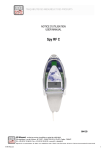
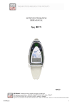
NOTICE D’UTILISATION USER MANUAL Spy RF Test 06576C TABLE OF CONTENTS I. INTRODUCTION ............................................................................................................................................................ 8 a. Equipment.................................................................................................................................................................................. 8 b. Symbols ..................................................................................................................................................................................... 8 II. PRESENTATION............................................................................................................................................................ 8 a. Display ....................................................................................................................................................................................... 8 b. Complementary information .................................................................................................................................................... 8 III. SPY RF USE .................................................................................................................................................................. 9 a. Stop ............................................................................................................................................................................................ 9 b. Start ............................................................................................................................................................................................ 9 c. Finding right places of spy RF recorders ............................................................................................................................... 9 d. Finding right places of spy RF recorders ............................................................................................................................... 9 e. Installation ending .................................................................................................................................................................. 10 IV. BATTERY REPLACEMENT......................................................................................................................................... 10 V. RESET .......................................................................................................................................................................... 10 VI FEATURES .................................................................................................................................................................. 10 VII. WARRANTY ................................................................................................................................................................. 10 VIII MAINTENANCE CONTRACT ...................................................................................................................................... 11 IX ENVIRONMENT PROTECTION ................................................................................................................................... 11 ©JRI Maxant 7 I. INTRODUCTION Congratulations, you own SPY RF TesT ! With its software, with the Spy RF ModeM TesT this device enables you to determine precisely the position of your SPY RF recorders in an installation. Indeed, the presence of obstacles (walls, partitions, furniture, people, diverse objects…) on the radio waves path between a modem and a recorder weakens the signal, what could disturb an effective radio transmission. The nature and thickness of crossed walls must be taken into account. It is to notice that the thickness of an obstacle should be measured in the radio signal direction: it is harder for a radio signal to cross a wall obliquely than perpendicularly. a) b) Equipment 1 SPY RF Test 1 User manual Symbols RECYCLING : do not throw in a rubbish dump or in a domestic waste container. Comply to the regulation to throw away the device. POWER SUPPLY : this device is powered by a cotinuous current delivered by a main power supply adaptor (230VAC). Comply to the security and utilization regulations of electric power. Use a an electric installation complying to these regulations CE MARKING :this equipment is certified to comply with the European regulation for the electric security, inflammability, disturbing radiation emission and immunity to surrounding electric disturbances. FCC ID: W45 03330 This device complies with Part 15 of the FCC Rules. Operation is subject to the following two conditions: (1) this device may not cause harmful interference, and (2) this device must accept any interference received, including interference that may cause undesired operation In accordance with FCC requirements, changes or modifications not expressly approved by JRI Maxant could void the user's authority to operate this product. NOTE: This equipment has been tested and found to comply with the limits for a Class A digital device, pursuant to Part 15 of the FCC Rules. These limits are designed to provide reasonable protection against harmful interference when the equipment is operated in a commercial environment. This equipment generates, uses and can radiate radio frequency energy and, if not installed and used in accordance with the instruction manual, may cause harmful interference to radio communications. Operation of this equipment in a residential area is likely to cause harmful interference in which case the user will be required to correct the interference at his own expense II. PRESENTATION Pushbutton Battery cover Display a) Display Indication of the radio reception level In % Bar graph b) Complementary information Low battery. You must change it. ©JRI Maxant 8 III. SPY RF USE a) Stop At reception, the SPY RF TesT is stopped. To activate it, you have to press on the button. b) Start The green led lights continuously. The Spy RF TesT receive in 25mW (like any Spy RF except Spy RF RelaY) To stop the SPY RF TesT, please press twice again the pushbutton. c) Finding right places of spy RF recorders Plug the Spy RF ModeM on the main power. The green led must light on. Turn on the Spy RF TesT. The green light must light on. Maximum reception level Look for the best position (> 80%) according to the screen indications . Repeat the operation as many times as necessary, depending on the number of recorders you have to place. If the level is below 80%, find another position or if it will be necessary to use a Spy RF RelaY. d) Finding right places of Spy RF RelaY Plug the Spy RF ModeM on the main power. The green led must light on. Press the button on the side of the ModeM to switch the power to 500mW; The red led must light on Turn on the Spy RF Test and then press the pushbutton to switch the power to 500mW. The red led must light on Look for the best position (> 80%) according to the screen indications. Repeat the operation as many times as necessary, depending on the number of Spy RF RelaY you have to place regarding the position of the Spy RF RelaY. Once the position determined, move the ModeM Spy RF TestT to this position and search the position of the Spy RF recorders (see III 3). If the level is below 80%, it is necessary to use a 2nd Spy RF RelaY, so repeat the section (III 4) ©JRI Maxant 9 e) Installation ending Once all you recorders are installed, you have to stop the SPY RF TesT by pressing on its pushbutton. IV. BATTERY REPLACEMENT When the SPY RF battery has to be replaced, the LCD screen displays the following message: To replace the battery, follow the instructions below: 3 2 1 1 b 2 Never unscrew. This will cancel the warranty Open the battery cover 3 a a) Unplug the battery connector. b) Short circuit the 2 pins with a screwdriver c) Connect the new battery d) Change the seal e) Close the battery cover KEEP THE BATERY FAR FROM THE FIRE ; DO NOT TRY TO RELOAD OR TO SHORT CIRCUIT IT. USE ONLY BATTERIES SUPPLIED BY JRI Maxant (REF 06569) V. RESET If the device does not work anymore (cannot turn it on…), use the Reset function in the same way as the battery change VI. FEATURES FEATURES Operating conditions Température of storage Radio band Battery lifetime Dimensions Protection degree CE ERM Conformity FCC Conformity ©JRI Maxant SPY RF TesT -30 +70°C -40 + 85°C 868MHz or 902MHz 2 ans 123x69x30mm IP65 EN 301 489 / EN 61000 / EN 61010 / EN 55022 / EN 300 220 FCC part 15 10 VII. WARRANTY JRI Maxant products carry a one year warranty and guarantee against defects in their components or workmanship. During this period if any product supplied by the Company proves on inspection to be defective, the Company will at its own option replace the same or refund to the Buyer the price of the product. In no circumstances will JRI Maxant' liability exceed the price of the product paid by the buyer or the cost of replacement. JRI Maxant shall not in any event be liable to the Buyer for any indirect or consequential loss or damage costs or expenses whatsoever which might arise out of or in connection with the supply of the product or its consequent use. Consequently, the products warrantee and guarantee specified above, does not cover damage caused by fair wear and tear, abnormal storage conditions, incorrect use, accidental misuse, abuse, neglect, misapplication or modification, or use with nonJRI Maxant' hardware/software. No warranty of fitness for a particular purpose is offered and the user assumes the entire risk of using the product. In line with our policy of continuous development, we reserve the right to amend our product specification without prior notice. VIII. MAINTENANCE CONTRACT How to optimize your radio frequency installation? RF measuring systems communicate by radio frequency. However, there may be several factors that can modify the radio ways already defined, such as moving from a building, adding walls, … Radio frequency requires thus a periodical follow up performed by specialists. That’s why JRI Maxant has created maintenance contracts. We bring you a global solution which makes your maintenance easier. This overall service offer includes maintenance and also metrological services, which ensure you that your system is fully performant. You won’t worry about your devices maintenance anymore ! With this maintenance contract you will benefit for a minimal period of 2 years from the following advantages: - material verification once or twice a year - warranty extension - telemaintenance - telephone assistance +33 (0) 892 680 933 (0,282 € HT/min) - material replacement on site or by return in our manufacture - metrological certificates: verification of measurement accuracy - battery change - access to new software versions and updates - on-site intervention time within 3 open days after problem identification by our experts IX. ENVIRONMENT PROTECTION JRI Maxant recommends to our customers to throw away their measuring and recording devices which are unserviceable and/or beyond repair in a way that is appropriate to environment protection. Insofar as the production of waste cannot be avoided, it is best to re-use them by proceeding with adapted recycling depending on the material used and considering the environment protection. RoHS Directive The ROHS European Directive rules and limits the presence of hazardous substances in electrical and electronic equipments (EEE). In the article 2, the scope of this Directive excludes "9. Monitoring and Control Instruments" and our products are part of this category. Nevertheless, our company has decided to apply the whole dispositions of this Directive for all our new electronic devices which will comply to this 2002/95/CE Directive. ©JRI Maxant 11