1
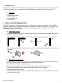
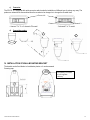
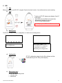
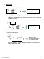
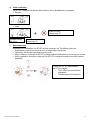
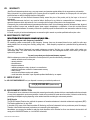
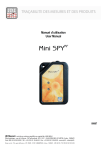
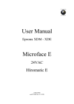
Manuel d’utilisation
User manual
RF
SPY Tc
06252 A
TABLE OF CONTENTS
I.
INTRODUCTION ..........................................................................................................................................................14
a)
II.
Equipment ............................................................................................................................................................................... 14
INSTALLATION RECOMMANDATIONS .....................................................................................................................14
a)
Perturbations sources ............................................................................................................................................................ 14
b)
installation recommendations ............................................................................................................................................... 14
III.
PRESENTATION..........................................................................................................................................................15
a)
Display ..................................................................................................................................................................................... 15
b)
Complementary information .................................................................................................................................................. 15
c)
Connector ................................................................................................................................................................................ 16
d)
Connecting probes ................................................................................................................................................................. 16
IV. INSTALLATION OF WALL-MOUNTING BRACKET ...................................................................................................16
V.
USE ..............................................................................................................................................................................17
a)
Stop .......................................................................................................................................................................................... 17
b)
Start.......................................................................................................................................................................................... 17
c)
Waiting mode .......................................................................................................................................................................... 17
d)
Configuration........................................................................................................................................................................... 17
e)
Measurement start .................................................................................................................................................................. 17
f)
Automatic start........................................................................................................................................................................ 18
g)
Manual start............................................................................................................................................................................ 18
h)
Alarm visualisation ................................................................................................................................................................. 19
i)
Measurement stop .................................................................................................................................................................. 19
j)
Auto control or top zone ........................................................................................................................................................ 20
k)
Leds and pushbutton actions fonctionning ......................................................................................................................... 20
VI. BATTERY CHANGE ....................................................................................................................................................21
VII. FEATURES ..................................................................................................................................................................21
VIII. WARRANTY.................................................................................................................................................................22
IX. MAINTENANCE CONTRACT ......................................................................................................................................22
X.
NEED OF HELP ? ........................................................................................................................................................22
XI. ENVIRONMENT PROTECTION...................................................................................................................................22
©Jules Richard Instruments
13
I. INTRODUCTION
Congratulations, you own a SPY RF Tc. This device is equipped with 1 or 2 thermocouple inputs. It enables you to record 1
or 2 temperature (depending on the model) and to transfer wirelessly the recorded data by radio frequency to a PC.
a)
Equipment
¾ 1 SPY RF Tc
¾ 1 wall-mounting bracket
¾ 1 adhesive plaster
¾ 1 connector protection
¾ 1 user manual
II. INSTALLATION RECOMMANDATIONS
The Spy RF is a recorder of physical parameters able to communicate wirelessly with the operating software SIRIUS.
The wireless communication is based on radio frequency. As we are daily in contact with it (radio, TV…) it is easy to think
that it always works. These true if basic rules on recorders positioning are respected concerning because wireless
communication is subject to perturbations.
a)
Perturbations sources
¾ Presence of obstacles in the way of the waves between the Spy RF ModeM and the Spy Rf (wall, ceiling, person,
furniture…) or close to the antena.
¾ Obstacles thickness in the way of the waves. The absorption is more important in diagonal as perpendicularly
¾ Waves cannot pass through full metallic walls. On the other hand, a perforated wall allows the waves passing with
attenuatinon
b)
installation recommendations
¾ Place the devices at ~2m hight and arround 30 to 40cm from the ceiling to avoid obstacles and moving persons.
¾ If possible, place the Spy RF in central position regarding the Spy RF recorders.
¾ Try to place them preferably at sight of each other .
¾ On the wall, it is preferable to them aside by using the special bracket (ref 08512) of the catalog.
¾ Place the antenna above the top the monitored unit (fridge, incubator, oven, cold rooms…),.
¾ Never place the Spy RF horizontally.
¾ If some difficulties persist, it is possible to use Spy Rf RelaY (repeaters) or to connect another Spy RF ModeM to
the Ethernet network (LAN).
©Jules Richard Instruments
14
III. PRESENTATION
Battery
trap door
Alarm LED (red)
Working LED
(green)
Push button
Display
Connectors
Wall-mounting bracket
SPY RF U recorder
a)
Connector IP65
protection
Display
Recording mode
Waiting mode
Memory status
Radio activity
Overpassed
thresholds
indicators
Channel N°
b)
Measurement
Non-programmed
Complementary information
Full memory. You must transfer the data to your PC.
Low battery. You must change the battery.
©Jules Richard Instruments
15
c)
Connector
The SPY RF U is equipped with rapid connectors which make the installation of different type of probes very easy. The
probes can otherwise be disconnected from the recorder to be changed or to change the recorder itself.
Front side
Channel 1
1 channel T in °C or 2 channels TH model
d)
Channel 2
2 channels T in °C model
Connecting probes
2
1
3
4
IV. INSTALLATION OF WALL-MOUNTING BRACKET
The bracket can be fixed thanks to its adhesive plaster or it can be screwed.
Screwing map
Possibility to install
a lock against
robbery
©Jules Richard Instruments
16
V. USE
a)
Stop
When you receive it, your SPY RF is stopped. Only the time clock is active. It can neither emit nor receive anything.
b) Start
To start your SPY RF, please press between 5 and 10”
on the button:
- the 2 LEDs are on and flash at the same time
- all the display segments are also on
- SPY RF is now in waiting mode
Remark: If you press >10’’ => no effect => remains off
c)
Waiting mode
The SPY RF is ready to receive a configuration or to start a new recording session.
The triangles are on: there is
no configuration.
d)
The symbol “Halt” is on:
- the SPY RF is configured
- possibility to restart it
depending on configuration
Configuration
SPY RF configuration is done from the Sirius software and then
transferred into your SPY RF by radio frequency.
e)
Measurement start
The SPY RF has 2 starting mode:
¾ automatic start
¾ manual start
©Jules Richard Instruments
17
f)
Automatic start
Your SPY RF starts recording:
¾
automatically when the configuration is transferred,
Working LED (green):
2’’ => starting measurements
then flashes every 1 minute
+
It displays the temperature in °C degrees, channel number, measurement unit and memory status.
The green LED flashes every minute.
The temperature, threshold indicator, channel number and a red LED flashes every 15 sec in case the
threshold limit is overpassed.
¾
at a programmed date and time:
dd / mm / yy
hh / mm / ss
+
g)
Working LED (green):
2’’ => starting measurements
then flashes every 1 minute
Manual start
¾
Press shortly on the pushbutton
+
Working LED (green):
2’’ => starting measurements
then flashes every 1 minute
It displays the temperature in °C degrees, channel number, measurement unit and memory status.
The green LED flashes every minute.
©Jules Richard Instruments
18
h)
Alarm visualisation
The SPY RF is equipped with different alarm indicators, when a threshold limit is overpassed.
Pre alarm
¾
¾
Alarm
+
Threshold indicator
High or low
i)
Alarm LED (red):
Flashes every 15’’.
Value measured
Flashes every 15”
Measurement stop
Depending on the configuration, the SPY RF can stop recording or not. The different options are:
¾ Rolling memory: once the memory is full, the new values replace the old ones.
¾ Full memory: the recorder stops when its memory is full.
¾ With the software: you can put the SPY RF in standby mode with Sirius when you do not use your recorder.
¾ With the pushbutton: this option is valid only if the SPY RF is configured in transport mode with a start by
pushbutton.
To stop your SPY RF, press between 5
and 10” on the button:
- The 2 LEDs are on and then flash
alternatively.
- The screen goes off, Halt goes on.
©Jules Richard Instruments
19
j)
Auto control or top zone
The type of action depends on the SPY RF configuration.
TOP ZONE = Transport mode
and
AUTO CONTROL = Storage mode
This function enables you to customise an action of measurement check-up. You just have to press shortly on
the pushbutton.
T° OK: green LED is
on during 10”.
+
Alarm LED (red) is on
during 10”.
+
The action is recorded and will appear on the curve when you process the data with your software Sirius.
k)
Leds and pushbutton actions fonctionning
The green led is on 2’’ when the measurement strarts and then flash each 1’ in recording mode.
Specials fonctionning regarding the recorder using mode
Device set up in storage mode
Pushbutton pressing
< 5"
Mode
OFF
-
Waiting setup
Starting measurements
Pushbutton
Red led 2"
The 2 leds are on and
flash at the same time.
-
Green led 2" = begining of
measurements
-
-
-
-
-
Green led 10" = auto control
-
Delayed (date & time)
Immediatly
Mesure
5’’> pressing <10’’
Device set up in transportation mode
Pushbutton pressing
Mode
Off
Waiting setup
< 5"
5"<appui>10"
-
The 2 leds are on and flash at
the same time.
Red led 2"
-
Green led 2" = begining of
measurements
-
Starting measurements
Pushbutton
The 2 leds are on and flash at
the same time = Waiting for
Delayed (date & time)
starting measurements
Immediatly
-
The 2 LEDs are on and then
flash alternatively = ending
Green led 10" = Top zone
The 2 LEDs are on and then
flash alternatively = ending
measurements
Mesure
measurements
©Jules Richard Instruments
20
VI. BATTERY CHANGE
When the SPY RF battery has to be replaced, the LCD screen displays the following message:
!
DOWNLOAD THE MEMORY BEFORE CHANGING THE
BATTERY. NEVER WAIT UNTIL THE BATTERY IS
EMPTY OR THE DATA WILL BE DELETED.
To replace the battery, follow the instructions below:
1
2
3
a
Open the battery cover
!
Never unscrew.
this can cancel
the guaranty
Pull up the connector “a”
Shunt the 2 pins on the board
Plug the new battery
Change the seal
Close the battery cover
Beware
! Keep the battery far from fire. Don’t
try to reload it or to short-circuit it.
BEWARE: ONLY USE BATTERIES SUPPLIED BY JULES RICHARD INSTRUMENTS (REF: 06569)
VII. FEATURES
FEATURES
Measurement range
Number of channels
Type of input
Accuracy
Recording interval
Memory size
Operating conditions
Temperature for storage
Radio range (in free field)
Radio band
Battery lifetime
Dimensions
Protection level
CE ERM conformity
©Jules Richard Instruments
SPY RF TC
Depending of the sensor used in the limit
of -200 +1370°C
1 or 2
Thermocouple K
±0,3°C on full range without sensor
1s to 90 min
20 000 measurements
-30 +70°C
-40 + 85°C
1 km
868MHz
2 years
123x69x30mm
IP65
EN 301 489 / EN 61000 / EN 61010
EN 55022 / EN 300 220
21
VIII.
WARRANTY
Jules Richard Instruments products carry a one year warranty and guarantee against defects in their components or workmanship.
During this period if any product supplied by the Company proves on inspection to be defective, the Company will at its own option
replace the same or refund to the Buyer the price of the product.
In no circumstances will Jules Richard Instruments' liability exceed the price of the product paid by the buyer or the cost of
replacement.
Jules Richard Instruments shall not in any event be liable to the Buyer for any indirect or consequential loss or damage costs or
expenses whatsoever which might arise out of or in connection with the supply of the product or its consequent use.
Consequently, the products warrantee and guarantee specified above, does not cover damage caused by fair wear and tear, abnormal
storage conditions, incorrect use, accidental misuse, abuse, neglect, misapplication or modification, or use with non-Jules Richard
Instruments' hardware/software. No warranty of fitness for a particular purpose is offered and the user assumes the entire risk of using
the product.
In line with our policy of continuous development, we reserve the right to amend our product specification without prior notice.
IX. MAINTENANCE CONTRACT
Jules Richard Instruments remains at your side...
How to optimize your radio frequency installation?
RF measuring systems communicate by radio frequency. However, there may be several factors that can modify the radio ways
already defined, such as moving from a building, adding walls, … Radio frequency requires thus a periodical follow up performed by
specialists.
That’s why Jules Richard Instruments has created maintenance contracts. We bring you a global solution which makes your
maintenance easier. This overall service offer includes maintenance and also metrological services, which ensure you that your
system is fully performant.
You won’t worry about your devices maintenance anymore !
With this maintenance contract you will benefit for a minimal period of 2 years from the following advantages:
- material verification once or twice a year
- warranty extension
- telemaintenance
- telephone assistance
- material replacement on site or by return in our manufacture
- metrological certificates: verification of measurement accuracy
- battery change
- access to new software versions and updates
- on-site intervention time within 3 open days after problem identification by our experts
X. NEED OF HELP ?
Our JRI CUSTOMER SERVICE is at your disposal to answer your technical questions at:
+33 (0) 892 680 933 (0,282 € HT/min)
XI. ENVIRONMENT PROTECTION
JRI recommends to our customers to throw away their measuring and recording devices which are unserviceable and/or beyond repair
in a way that is appropriate to environment protection. Insofar as the production of waste cannot be avoided, it is best to re-use them by
proceeding with adapted recycling depending on the material used and considering the environment protection.
RoHS Directive
The ROHS European Directive rules and limits the presence of hazardous substances in electrical and electronic equipments (EEE).
This Directive applies from 1st June 2006.
In the article 2, the scope of this Directive excludes "9. Monitoring and Control Instruments" and our products are part of this category.
Therefore, Jules Richard Instruments’ products are not concerned by this new directive.
Nevertheless, our company has decided to apply the whole dispositions of this Directive for all our new electronic devices which will
comply to this 2002/95/CE Directive, on 1st June 2006 at the latest.
©Jules Richard Instruments
22
©Jules Richard Instruments
23