1
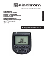
USER MANUAL
GEBRAUCHSANLEITUNG
MANUEL D’UTILISATION
MANUAL DE FUNCIONAMIENTO
MANUALE D’USO
GEBRUIKSAANWIJZING
РУКОВОДСТВО ПО ЭКСПЛУАТАЦИИ
ユーザーマニュアル
用户手册
EN
DE
FR
IT
ES
NL
RU
JP
CN
User Manual
TABLE OF CONTENTS
EN
DECLARATION OF CONFORMITY
5
VERSIONS
6
FEATURES
6
INSTALLING THE BATTERIES
7
BATTERIES
7
COMPATIBILITY
8
TRIGGERING
8
REMOTE CONTROL
8
FREQUENCY CHANNELS
8
TECHNICAL DATA
9
HOT-SHOE ADAPTER
10
MOUNTING ON THE CAMERA
10
DISPLAY
11
BUTTONS
12
SETUP MENU
14
MANUFACTURING RESET
16
TROUBLESHOOTING
16
FIRMWARE UPDATE
18
Tolerances and specifications conform to IEC and CE standards. Technical data subject to change without notice.
2
User Manual
INTRODUCTION
Dear Photographer,
Thank you for choosing ELINCHROM.
EN
All Elinchrom products are manufactured using the most advanced technology. Carefully selected components
are used to ensure the highest quality and the equipment is subjected to many tests both during and after
manufacture. We trust that it will give you many years of reliable service.
Please read this User Manual carefully before you use your new Elinchrom product. You will find information
for your safety and how to benefit from all the programmable features.
This Manual may show images of products with accessories which are not part of sets or single units.
Elinchrom set and single unit configurations may change without advice and may differ in other countries.
For further details, upgrades, news and the latest information about the Elinchrom system, please regularly
visit the Elinchrom website. The latest user guides and technical specifications can be downloaded from the
“Support” area.
Technical data, features and functions of Elinchrom flash units and accessories may change without notice.
The listed specification can differ due to tolerances in components or measuring instruments. Technical data is
subject to change. No guarantee for misprints.
Please check for the most recent manual at our website: www.elinchrom.com/support
Thanks,
Your Elinchrom-Team
3
User Manual
EN
The Product is classified as a Class 3R laser
product, according to the following standards
IEC/EN 60825-1 “Radiation Safety of Laser
Products”.
Class 3R: A Class 3R Laser is considered safe if
handled carefully, with restricted beam viewing.
With a class 3R laser, the MPE can be exceeded,
but with a low risk of injury. Visible continuous
lasers in Class 3R are limited to 5mW. For other
wavelengths and for pulsed lasers, other limits
apply.
4
User Manual
DECLARATION OF CONFORMITY USA AND CANADA
EN This device complies with Part 15 of the FCC Rules and with Industry Canada licence-exempt RSS
standard(s). Operation is subject to the following two conditions: (1) this device may not cause harmful
interference, and (2) this device must accept any interference received, including interference that may cause
undesired operation. This product complies with the Canadian ICES-003 Class B specifications.
FR Le présent appareil est conforme aux CNR d’Industrie Canada applicables aux appareils radio exempts
de licence. L’exploitation est autorisée aux deux conditions suivantes(1) ce dispositif ne doit pas produire
de brouillage préjudiciable, et (2) ce dispositif doit accepter tout brouillage radioélectrique subi, même si le
brouillage est susceptible d’en compromettre le fonctionnement. Cet appareil numérique de la classe B est
conforme à la norme NMB-003 du Canada.
EN
Radiation Exposure Statement
EN This equipment complies with portable RF exposure limit in Canada and the USA set forth an
uncontrolled environment and is safe for intended operation as described in this manual. Further RF exposure
reduction can be achieved if the product can be kept as far as possible from the user body.
FR Le produit est conforme aux limites d’exposition pour les appareils portables RF pour les Etats- Unis et le
Canada établies pour un environnement non contrôlé. Le produit est sûr pour un fonctionnement tel que décrit
dans ce manuel. La réduction aux expositions RF peut être augmentée si l’appareil peut être utilisé aussi loin
que possible du corps de l’utilisateur.
FCC Class B Compliance note
This equipment has been tested and found to comply with the limits for a Class B digital device, pursuant
to Part 15 of the FCC Rules. These limits are designed to provide reasonable protection against harmful
interference in a residential installation. This equipment generates, uses and can radiate radio frequency energy
and, if not installed and used in accordance with the instructions, may cause harmful interference to radio
communications. However, there is no guarantee that interference will not occur in a particular installation. If
this equipment does cause harmful interference to radio or television reception, which can be determined by
turning the equipment off and on, the user is encouraged to try to correct the interference by one or more of
the following measures:
•
Reorient or relocate the receiving antenna.
•
Increase the separation between the equipment and receiver.
•
Connect the equipment into an outlet on a circuit different from that to which the receiver is connected.
•
Consult the dealer or an experienced radio/television technician for help.
Any changes or modifications not expressly approved by the party responsible for compliance could void
the user’s authority to operate this equipment. This device is limited to operation on permissible Part 15
frequencies, and it does not have the ability to be configured by end users or professional installers to operate
outside the authorized bands.
5
User Manual
EL SKYPORT TRANSMITTER PLUS HS
VERSIONS
The ELSP Transmitter Plus HS is available for the following cameras
EN
•
Canon
•
Nikon
FEATURES
•
Large graphic control display.
•
Display Illumination in green or red (green for Normal Sync Mode, red for Speed Sync Mode).
•
Fast access buttons and rotating wheel for easy control.
•
Secure Hot-Shoe connection with bayonet locking system.
•
Standard 2 AA Batteries (accepts rechargeable batteries).
•
2.5mm jack trigger output.
•
Firmware update with integrated Mini USB socket.
•
40 Remote channels.
•
20 frequency channels* in Normal Sync mode.
•
20 frequency channels* in Speed Sync mode.
•
4 Groups and ALL .
•
EL-Skyport Sync Modes.
•
•
Normal Sync Mode (maximum distance range).
•
Speed Sync Mode (faster shutter speed particularly when HS is activated,
but reduced distance range).
Sync Modes***.
•
Standard (using the middle contact of the Hot-Shoe).
•
HS **** (Sync up to 1/8000s, controlled automatically).
•
ODS (manual Over-Drive-Sync) fine tune the timing of HS for maximum power and even exposure.
•
Second curtain sync mode****.
•
AF Light integrated***.
•
Auto MOD *** to control the modelling light of Elinchrom flash units for focusing.
•
•
Shutter Mode***** (the half pressed shutter release controls the modelling lamp).
•
DOF Mode (the camera “DOF” (Depth Of Focus) button controls the modelling lamp).
REMOTE Control** with automatic feedback from Elinchrom flash units.
•
EL – flash units can be controlled “All” together, in “Groups” or “Single” units.
•
Flash power up & down.
•
Modelling lamp on/off or intensity up & down.
•
Sleep mode and Auto OFF mode programmable.
•
RESET to standard settings.
*
For all the latest Elinchrom flash units with 20 frequency channels, and compatible with earlier models.
**
For all Elinchrom flash units with built-in EL-Skyport Receiver and Transceiver.
*** Extended features for Canon and Nikon cameras with TTL Hot-shoe
(Limited features for Nikon, see below).
**** These features are not supported by Nikon, but can be activated in the camera menu.
***** Not supported by Nikon.
6
User Manual
INSTALLING THE BATTERIES
Press the battery compartment cover and slide it in the direction of the arrow to open the battery cover
(See Picture 1).
Insert the batteries. Make sure the “+” and “-” battery contacts are correctly oriented (See Picture 2).
(Note: Please use 2 pieces of AA alkaline batteries or AA type NIMH batteries).
Press cover against Transmitter and slide it back into the locked position.
EN
Press and slide
Picture 1
Picture 2
BATTERIES
•
2x AA batteries are used for the Transmitter.
•
Installing the batteries improperly will not damage the Transmitter.
•
Non-rechargeable (dry cell) AA batteries like zinc–carbon, Alkaline types or rechargeable batteries in the
AA size such as nickel-cadmium (NiCd) or nickel-metal hydride (NiMH) can be used.
•
Do not mix battery types.
•
Do not use Lithium AA batteries in this transmitter.
7
User Manual
COMPATIBILITY
There are three different Elinchrom EL-Skyport flash unit Generations in the market:
1ST GENERATION
•
EL-Skyport Transceiver RX module (Style RX, Digital RX, Ranger RX).
2ND GENERATION
EN
•
Built-in EL-Skyport module Mk1 (BRX, D-Lite RX, Quadra, Quadra Hybrid).
3RD GENERATION
•
Built-in EL-Skyport module Mk2 (ELC and ELB).
This generation offers extended distance range
TRIGGERING
Triggering works with all existing Elinchrom flash units with built-in or plug-in EL-Skyport Transceivers.
REMOTE CONTROL
WHEN ALL OR GROUP 1 - 4 IS SELECTED
•
All Elinchrom flash units with EL-Skyport are supported when changing “PWR±, MOD± or MOD on/off”.
When modelling lamp power settings are changed with the MOD on/off or MOD+/- button,the Elinchrom
flash in use will switch to free modelling mode. To return to proportional modelling lamp mode, settings
must be made on the EL flash unit.
•
Some units do not support all modelling features, “--“ is then displayed (i.e. for Ranger, Quadra, ELB400).
WHEN A SINGLE UNIT IS SELECTED
•
The selected unit is highlighted with a frame in the display and can be controlled individually.
•
Only Elinchrom flash units with built-in EL-Skyport receivers of the 2nd and 3rd generation are supported.
Note:
1st Generation units are detected, but will show “--“ in the display. There is no feedback of the unit settings to
the EL-Syport Transmitter Plus HS, but they will be triggered normally.
FREQUENCY CHANNELS
Some older Elinchrom flash units with EL-Skyport built-in will support Frequency channels 1 to 4 or 1 to 8
(such as BRX, D-Lite RX, Quadra).
The latest Elinchrom flash units with EL-Skyport built-in will support up to 20 different Frequency channels 1 to
20 (ELC, ELB).
8
User Manual
TECHNICAL DATA
PARAMETER
SPECIFICATION
VERSIONS
Canon, Nikon.
TRIGGERING COMPATIBILITY
ALL Elinchrom flash units with built-in EL-Skyport Receiver or Transceiver
and the EL-Skyport RX Transceiver modules, plus EL-Skyport Universal.
REMOTE CONTROL COMPATIBILITY
ALL Elinchrom flash units with built-in EL-Skyport Transceiver: ELC Pro
HD, ELB 400, Ranger Quadra RX, Quadra Hybrid, D-Lite RX series, BRX
Series, Master RX Series and FRX series (NOTE: EL-Units used with the
plug-in Transceiver RX module have limited remote features ).
DISTANCE RANGE
Indoor > 60m.
Outdoor > 200m.
Note:
The full distance range is available with the latest Elinchrom flash units
such as ELC or ELB. Other, or older Elinchrom flash units will have a
limited distance range.
BATTERIES
2x AA batteries (standard or rechargeable).
BATTERY LIFETIME
Depends on the type of batteries and the usage.
EN
For two standard batteries with 1000mAh each it is approx. 35 hours
working time and more than 15000 trigger releases.
REMOTE CONTROL
Max. 10 units can be detected displayed and remote controlled.
FREQUENCY CHANNELS
20 channels in Normal mode and 20 channels in Speed mode.
EL-SKYPORT MODES (ELSP)
Normal / Speed - Sync mode.
TRIGGER/CONTROL GROUPS
“All” or in “Groups” (Group 1 to 4).
SYNC MODES
Standard, HS (with or without ODS), Second Curtain.
USB SOCKET
For firmware updating.
SR SOCKET
Trigger Output 2.5mm Phone Jack mono (max. sync-voltage 3VDC).
DIMENSIONS (W x L x H)
69 x 84 x 59 mm (2.7x 3.3x 2.3 in.)
WEIGHT
Approx. 170g (6 oz) ,including 2x AA-batteries. 120g (4.2 oz) without
batteries.
9
User Manual
HOT-SHOE ADAPTER
FEATURES
The Elinchrom Skyport Plus HS transmitter can be used for basic trigger with power control for any camera
having a “hot shoe’ type flash connection. The features described below require a Canon or Nikon camera
that is compatible with the Skyport system. To operate properly, the Skyport HS transmitter offers special
connection pins for communication with the attached camera.
EN
There are two different Elinchrom Transmitter versions available:
•
Canon for Canon EOS type A cameras compatible with ETTLII/ETTL autoflash.
•
Nikon for Nikon DSLR cameras compatible with iTTL flash units.
Specilized communication terminals in the camera’s hotshoe mount enable the following Elinchrom Skyport
HS features:
•
SYNC Mode
•
HS and ODS Mode
•
Second Curtain Sync
•
Auto MOD
•
AF Light
Note: Not all cameras are supported for all features.
LIST OF TESTED CAMERAS
The latest summary of camera models and supported features can be found on the Elinchrom website at:
http://www.elinchrom.com/support.php
MOUNTING ON THE CAMERA
An easy locking bayonet mechanism is used to lock the Transmitter securely into the Camera’s hotshoe.
ATTACHING
1. Turn off the camera and the EL-Skyport transmitter.
2. Align the EL-Skyport transmitter hotshoe with the camera’s hotshoe mount.
3. Slide it all the way into the camera’s hotshoe mount.
4. Move the tab on the locking ring to the right until it clicks in place. (See picture 3)
DETACHING
1. Unlock: press the lock-release button and move the tab all the way to the left. (see picture 4)
2. Slide the EL-Skyport transmitter off the camera’s hotshoe mount.
10
User Manual
DISPLAY
The graphic display shows the status and settings of the Elinchrom unit.
The display illumination can be switched on or off.
In Normal Sync mode, the illumination is green. In Speed Sync mode, the illumination is red.
The contrast of the display can be adjusted in the setup menu.
The top bar of the display shows the status of the Elinchrom Transmitter.
The bottom bar in the display shows the functions of the 4 speed buttons.
The middle area shows a list of the Elinchrom flash units detected, It also shows setup items for the Setup
menu when selected.
EN
DISPLAY PANEL - DASHBOARD
Sync mode
HS: hypersync *
second curtain *
TM
Frequency
Number of unit
ODS status
Modelling lamp
mode
Groups
D: DOF
S: Shutter **
Skyport mode
Battery status
n: normal
s: speed
Column title
EL-unit(s)
Button function title
Power settings
Modelling lamp settings
Setup menu
Unit selection
DISPLAY PANEL - SETUP MENU
Menu list
Description/mode
Up/down list
*
Exit
In Nikon cameras, these features are activated in the camera’s menu.
** Not supported by the Nikon system.
11
User Manual
BUTTONS
Speed button 2
Speed button 3
Speed button 4
Speed button 1
EN
SR
Refresh
USB
To refresh manual
changes made on the flash unit
Group selection
Battery compartment cover
Test
On/Off
Press for 2 seconds
Rotation ring / Dial
Change value
Set
Lock
Press for 2 seconds
SPEED BUTTONS 1-4
The Speed Buttons enable quick setting of the functions indicated below. Functions in Bold type indicate the
function of these buttons when SETUP mode is selected.
SPEED BUTTON 1 (LEFT)
Pwr±
change the flash power in 1/10 f-stop up/down with the dial.
up
scroll up in the setup menu when SETUP is selected.
SPEED BUTTON 2 (MIDDLE LEFT)
Press this button once or twice to toggle between the modelling lamp features.
Mod
switch the modelling lamp on/off with the dial.
Mod±
change the modelling lamp power in 1/10 f-stop up/down with the dial.
down
scroll down in the setup menu when SETUP is selected.
SPEED BUTTON 3 (MIDDLE RIGHT)
Select
toggle between the displayed (found) Elinchrom flash units.
Flash and modelling lamp settings can be individually adjusted on the selected flash unit, when highlighted
with a frame.
After approx. 5 seconds the frame will disappear and adjustments in the settings will affect all units in all
Groups, when Group “ALL” is selected. If Group 1 – 4 is selected only the flash units in that Group will be
modified.
12
User Manual
SPEED BUTTON 4 (RIGHT)
Setup
by pressing this button the functions of the speed buttons will change and the SETUP menu is
selected. In the SETUP menu features can be adjusted and activated.
Exit
Exit the Setup menu and switch back to standard display mode.
ON/OFF
Press and hold for min. 2 seconds to switch the EL-SkyportTransmitter Plus HS On/Off.
EN
GROUP BUTTON
Press to toggle between 1 through 4 groups and “ALL.”
TEST BUTTON (WITH EL LOGO)
Pressing the TEST button will fire all flashes when “ALL” is selected or any single group, 1 through 4 is
selected. Please remember to deactivate photocells for accurate
EL-Skyport triggering of your flash units.
REFRESH BUTTON
Press the Refresh button any time power setting has been done on a separate EL flash unit to update the
power setting display of the Skyport HS.
If a Group is selected, only the information for that selected Group will refresh.
When “ALL” is selected, information for all groups will be refreshed.
A flash that was not scanned and found when the Skyport HS was switched ON cannot be added with the
Refresh feature.
If a flash is added, select SETUIP and SCAN in the setup menu or switch the transmitter OFF and ON again.
The refresh can take up to 4 seconds, depending on how many flash units are found and operated by the
transmitter.
Note:
To assure the most positive operation between the Skyport HS and EL flashes, flash power information is
transmitter by the EL flash only when power level changes are made or the Refresh button is pressed.
ROTATING RING / DIAL
Turn the Dial to select various functions and change power levels of the EL flashes.
SET / CONFIRMATION BUTTON (DIAL CENTRE BUTTON)
Press to confirm a modification made in the Setup menu.
Press to switch on the display illumination.
Press to return to normal operation when Skyport HS has switched to Standby mode.
Press 2s to lock all functions and settings. Press again to unlock.
The locking feature blocks the function of the dial and other buttons to prevent mis-setting while carrying the
Skyport HS.
13
User Manual
SETUP MENU
SCAN..
When the Skyport HS is switched ON, it will automatically search for Elinchrom flash units with built-in or plugin EL-Skyport Transceiver modules.
The Scan feature is also available in the Setup Menu. A re-scan is required, when new flash units have been
added to the lighting setup.
EN
To find EL flash units,
•
all EL flash units must be switched on,
•
all flashes must have built-in or plug-in EL-Skyport Transceiver modules.
•
the Transmitter Plus HS and the EL flash unit must be set for the same frequency channel settings.
FREQUENCY CHANNELS
Up to 20 EL-Skyport frequency channels can be selected.
Note:
•
Only the latest Elinchrom flash units (ELC 500/1000 Pro HD, ELB 400 and future versions)
will support up to 20 frequency channels.
•
All “RX” flash units will support up to 8 channels and some older Elinchrom flash units support
up to 4 channels.
ELSP MODE
The Skyport HS has two operating modes that offer different shooting functionality
Phil is using the above sentence as he doesn’t know what to say about this. The first sentence and note below
it should be at the bottom as they are operational info. The statement of Speed mode reducing communication
time has no interest to the user and thus is of no value to them.
•
Normal mode
Normal mode is compatible with the very first Elinchrom flash units incorporating EL-Skyport.
When selected, display illumination and status LED will light in green.
•
Speed mode
The Speed mode enables faster shutter speeds of up to 1/1000s depending on the camera using normal
flash synchronisation (i.e. for leaf shutter cameras and some mirrorless).
To use shutter speeds of up to 1/8000s the HS mode must be activated when used in both Normal and
Speed mode.The display illumination and status LED are displayed in red when is in speed mode.
Note:
•
The greatest working distance is available in Normal mode. Speed mode reduces working distance by
50%. Skyport transceivers in all remote flashes must have EL-Skyport mode capability to use Speed
mode.
SYNC MODE
Select the synchronization mode:
•
Standard mode
In Standard mode most cameras will work with shutter speeds up to 1/200s - 1/250s.
•
HS Hi-Sync mode*
In HS mode the shutter speed can be up to 1/8000s depending on the camera and the flash unit.
The HS mode requires flash units or flash heads with a long flash duration for best results.
Heads or flash units equipped with the A flash tubes (Action) are not recommended.
•
Second Curtain mode*
The Second Curtain mode gives the ability to fire the flash just before the shutter closes, for moving
effects.
*
14
With Nikon cameras, these features are activated within the camera menu.
User Manual
ODS SETUP
The Over-Drive-Sync (ODS) can improve the overall exposure, when the HS Sync mode is active.
ODS relies on flash units with long flash durations, so results will depend on the flash duration of the lights
used (which also changes at different power levels), as well as the camera used. Full frame cameras with large
sensors and slow shutters are unfortunately the hardest to get good results with, but lights with long enough
flash durations can still achieve clean frames all the way to 1/8000th. In addition using ODS, they can gain up
to 2 f-stops more light, essential when sun light must be overpowered.
The ODS Setup offers adjustment from 0.1 to 5.0 ms or can be switched off.
The ODS value will vary depending on the camera and the flash unit which is used and must be adjusted
manually
EN
Note:
•
Over-Drive-Sync (ODS) can only be used when the SYNC mode is set to HS.
•
When ODS is adjusted, the position of the flash cutoff (dark edge at top or bottom of picture) can be
moved within the frame. When switched OFF, the flash trigger point will be selected automatically when
in HS mode.
AUTO MOD
•
Off
The modelling light of the Elinchrom flash units does not change.
•
Shutter**
Pressing the camera’s shutter button for focusing will cause the modelling lamp of the EL flash unit will
switch on for a few seconds as an aid to focusing in low light. (Not supported by Nikon)
•
DOF
The Elinchrom flash units will switch on their modelling lamp for as long as the DOF (Depth of field)
button on the camera is held.
AF LIGHT
Activates the Auto-Focus assist light of the Skyport HS when the shutter release is half pressed for focusing
(check also camera settings).
KEY CLICK
When activated, pressing any control button will be indicated by a beep tone.
SLEEP
When not uise for a time, the Skyport HS will switch to Sleep Mode to save battery power.
Delay Sleep mode from 1 to 60 minutes or turn OFF.
AUTO OFF
The Skyport HS will automatically turn OFF when left unattended for a time.
Delay Auto Off start from 1 to 60 minutes or turn OFF.
When Sleep mode and Auto Off are both active, the Transmitter Plus HS will switch the power OFF at the user
set Sleep Mode delay.
CONTRAST
The display contrast can be adjusted from 80 to 120%
BACKLIGHT
The display illumination of the device can be switched on/off
*
With Nikon cameras, these features are activated within the camera menu.
**
Not supported by Nikon.
15
User Manual
MANUFACTURING RESET
Pressing and holding in the Left and Right Speed buttons while switching the Skyport HS ON (approximately
2 seconds) will reset the Skyport HS to manufacture settings. All user settings, except the display contrast, will
be reset.
FIRMWARE UPDATE
EN
To update the Firmware of the Transmitter Plus HS, the Elinchrom Transmitter HS Updater is required.
Available from the Elinchrom website.
TROUBLESHOOTING
Pressing and holding in the Left and Right Speed buttons while switching the Skyport HS ON (approximately
2 seconds) will reset the Skyport HS to manufacture settings. All user settings, except the display contrast, will
be reset.
HAVING THIS PROBLEM?
PLEASE CHECK THE FOLLOWING POINTS:
THE UNIT IS NOT SWITCHING ON
•
Check battery polarity and replace both
discharged batteries.
FLASH UNIT CANNOT BE TRIGGERED WHEN
THE MODE “ALL” IS SELECTED
•
Transmitter and receiver must have the same
frequency channel settings.
•
ELSP MODE: transmitter and receiver must
have the same synchronisation mode settings:
normal or speed sync mode.
•
Check that the EL-Skyport receiver in all ELunits with built-in receivers, is switched on.
•
Check that the transmitter version corresponds
to your Canon or Nikon camera.
•
Check the group settings of the EL- flash unit.
•
Reduce the distance to any unresponsive unit.
•
Transmitter and receiver must have the same
synchronisation mode settings: normal or speed
sync mode, and frequency channel settings.
SOME UNITS ARE NOT TRIGGERING WHEN
THE GROUP MODE IS SELECTED
THE TEST BUTTON WORKS, BUT THE CAMERA • Check the hotshoe fitting.
• Check the camera settings (turn hotshoe
WILL NOT TRIGGER FLASH UNITS
communication on).
SOME INFORMATION IS NOT DISPLAYED
ABOUT DIGITAL RX, RANGER RX OR STYLE
RX UNITS
16
•
Check that the transmitter version corresponds
to your Canon or Nikon camera.
•
Check the list of compatible cameras.
•
Units equipped with a plug-in Transceiver RX
are limited in remote features. These units
can however be triggered and controlled (but
with no visual feedback) by the EL-Skyport
Transmitter Plus HS.
User Manual
LIMITED DISTANCE RANGE:
•
Reposition the units.
•
Increase the distance from walls and ceilings.
•
ELSP Mode: In speed sync mode the distance
range is reduced by approximately 50 %,
switch back to normal sync mode.
•
Outdoors, the distance range could be reduced
due to humidity, interference, obstacles etc.
INTERFERENCE WITH OTHER 2.4 GHZ
NETWORKS, UNRELIABLE TRIGGERING:
•
Try another frequency channel for both
transmitter and the receiver of the EL-unit.
•
Reduce the distance between the flash unit and
transmitter.
HS MODE; SYNC UP TO 1/8000S:
•
Elinchrom Action (previously A) heads are not
optimised for the HS mode. To benefit from
better performance please use flash units with
Pro flashtubes (Standard or S previously) or
ideally use with dedicated HS heads.
•
ODS fine tuning helps to optimise HS
performance.
•
If there is visible banding please reduce the
shutter speed on your camera, or set ODS and
adjust to minimise or avoid banding.
•
HS functionality only works with Canon or Nikon
cameras and the appropriate transmitter.
SCANNING EL-UNITS:
•
NO EL-UNIT FOUND, OR SOME UNITS ARE
MISSING.
Switch on all enabled EL-units, than switch on
the EL-Skyport Transmitter Plus HS on or go to
setup and rescan.
•
Frequency, group and ELSP mode settings
must match with the transmitter.
•
Ensure that all EL-Skyport Transmitter Plus
HS enabled units are operating on the latest
firmware.
EN
17
User Manual
FREQUENCY CHANNEL FOR EL-SKYPORT SPEED RECEIVERS
This is not relevant to this product, but it may help with frequency set-up on legacy EL-Skyport units.
EN
DOWNLOAD THE EL-SKYPORT TRANSMITTER PLUS HS
USER GUIDE
Obtain the complete user guide using this link: http://bc.gs/elspths
DOWNLOAD CONFORMITY
Find your declaration for EC and USA & Canada c
onformity here: http://bc.gs/ec
FIRMWARE UPDATE BY USB PORT
Please download our lastest firmware and follow the instructions: http://bc.gs/fw
18