1
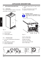
APPLIANCE DESCRIPTION
Technical data
For detailed technical data see sections
"Technical Data" on page 26 or page 28.
1.5
Faulty c.h. temperature
probe NTC
Faulty d.h.w temperature
probe NTC
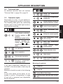
Operation lights
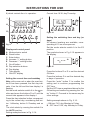
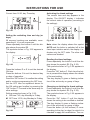
Three lights (10 in Fig. 1.3) give detailed indication regarding the operation of the boiler.
The following table gives the relationship
between each of the possible light combinations and their meaning.
Faulty primary circuit (no
water or absence of flow)
Lack of burner ignition
Safety thermostat lock
out
A short pulse every 4 seconds: stand-by condition.
Faulty fan control system
Function selector in
position.
Anti-freeze system active
1 second pulse every 2
seconds: normally operating boiler. Function
selector in
sition
or
Flue temperature probe
NTC lock out
Open flue temperature
probe NTC
po-
Faulty external
probe (if fitted)
temp.
C.h. operation
Flame detection error
D.h.w. operation
Other faults
Frost protect operation
Lack of power supply or
fauly electr. control p.c.b.
D.h.w. operation
Excessive temperature
on primary circuit
If the lights combination observed is not
included in the above table a fault may be
indicated.
Reference should be made to the following
table.
In this case switch off the boiler, as described in section "Extinguishing" to page
13 and call a competent and responsible
Service Engineer.
Meaning of symbols:
Lamp OFF
Lamp ON
Flashing lamp, alone or simultaneously with an other lamp
Flashing lamp, alternate with another
lamp
-9-
USE
1.4