1
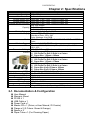
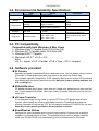
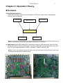
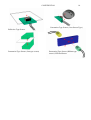
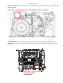
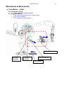
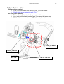
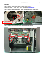
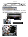
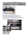
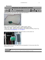
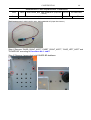
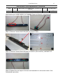
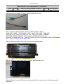
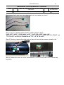
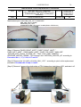
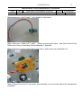
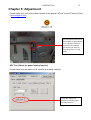
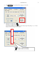
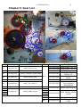
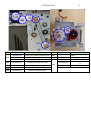
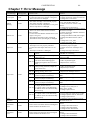
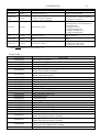
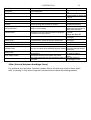
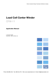
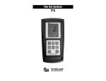
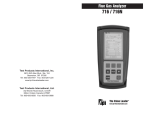
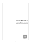
CONFIDENTIAL P510S Service Guide Version: 1.1 1 CONFIDENTIAL 2 Revision History Date Revision 2008/8/8 2009/04/22 2010/06/11 1.0 1.01 1.1 Description First Edition Add Paper jam error code 1. Updates “Error Message”. 2. TPH Voltage adjustment 3. Fine tune Chapter 4 Disassembly and Assembly. Remark P74 CONFIDENTIAL 3 Outlines: CHAPTER 1: INTRODUCTION ................................................................................................................................. 4 CHAPTER 2: SPECIFICATIONS ............................................................................................................................... 5 CHAPTER 3: OPERATION THEORY ........................................................................................................................ 7 CHAPTER 4: DISASSEMBLY & ASSEMBLY ......................................................................................................... 23 4-1 TOOLS REQUIRED .............................................................................................................................................................23 4-2 PROHIBITION ....................................................................................................................................................................23 4-3 PARTS REPLACEMENT PROCEDURE ........................................................................................................................................25 MAIN COVER REMOVAL PROCEDURE .................................................................................................................25 CASE_TOP_A5RT........................................................................................................................................................29 CIRCUIT BOARDS......................................................................................................................................................31 MAIN_BD........................................................................................................................................................................31 CARD_BD ......................................................................................................................................................................32 POWER BD....................................................................................................................................................................33 TPH_BD..........................................................................................................................................................................34 LCD_BD..........................................................................................................................................................................36 BUTTON_BD .................................................................................................................................................................38 MOTORS ....................................................................................................................................................................39 MTR STEP_7.5_6OHM_RBN_S_160MM ROHS (Ribbon reverse motor frame) ...............................................39 MTR STEP_7.5_6OHM_CAM_PLTN_200MM RED & MTR STEP_7.5_4OHM_CAM_PINCH_90MM (Cam Pinch & Cam Platen motor frame).......................................................................................................................40 MTR STEP_7.5_6OHM_RBN_T_350MM (Ribbon take motor frame)..................................................................41 MTR STEP_1.8_2.4V_2.5A CAPSTON_250MM (Capstan Motor)........................................................................42 MTR STEP_3.75_8.5OHM_PAPER_EXIT 240MM BL (Cutter door motor) .........................................................43 OTHER PARTS ...........................................................................................................................................................44 ROLLER_EXIT_PINCH_CUTTER_A5 ......................................................................................................................44 CUTTER_C104KZ (Cutter)..........................................................................................................................................46 Tray exit ..........................................................................................................................................................................47 TPH linkage....................................................................................................................................................................49 TPH 300DPI A5 GLAZE 70UM (TPH ASSY) ............................................................................................................51 CAPSTAN_ROLLER_A5..............................................................................................................................................55 ROLLER_PLATEN_NEW_A5 (Platen roller)..........................................................................................................57 ROLLER_PINCH_A5 (Pinch roller) ............................................................................................................................59 Tray feed.........................................................................................................................................................................61 SENSORS ..................................................................................................................................................................63 WIRE DOOR_SNR 310MM (Cover open Sensor) ...................................................................................................63 WIRE PAPER_BOX_SNR 390MM BLUE (Paper Box Sensor)..............................................................................64 WIRE PAPER_TYPE 590MM (Paper type Sensor) (white connector)..................................................................66 WIRE PAPER_OUT 680MM (Paper out Sensor) (red connector) .........................................................................67 WIRE LE_FEED_SNR 490MM (LE Sensor) .............................................................................................................68 WIRE JAM_SNR 340MM/ WIRE JAM_LED_290MM (Jam Sensor) .....................................................................69 WIRE RBN_SNR_LEFT 120MM/WIRE RBN_SNR_RIGHT 160MM/WIRE RBN_LED_LEFT 350MM/WIRE RBN_LED_RIGHT 470MM (Ribbon LED/Sensor) ............................................................................................70 WIRE CAM_PINCH 180MM (Cam sensors) .............................................................................................................72 WIRE SMART_CHIP 240MM (IC chip sensor) .........................................................................................................73 CHAPTER 5: ADJUSTMENT................................................................................................................................... 74 CHAPTER 6: GEAR LIST ........................................................................................................................................ 78 CHAPTER 7: ERROR MESSAGE ........................................................................................................................... 80 CHAPTER 8: CONTACT INFORMATION ............................................................................................................... 85 CONFIDENTIAL 4 Chapter 1: Introduction This document contains operation theory and parts replacement procedures that are intended to ease the task of transportation, usage, maintenance and parts replacement. The HiTi 510S is a new generation printer that is designed for fast and massive printing solution. As compare to other series, HiTi Research & Development Team has reduced many adjustment and alignment of mechanism and hardware of this printer to reduce the time and effort in servicing. CONFIDENTIAL 5 Chapter 2: Specifications Item Description Resolution Max Prints Size Printing Speed (6x4) Printing Speed (5x7) Printing Speed (6x8)(6x9) 300 x 300 dpi 6x9 borderless Less than 13 sec (From Y-Layer to Paper exit) Less than 20 sec (From Y-Layer to Paper exit) Less than 23 sec (From Y-Layer to Paper exit) 6x4: 330 images 5x7: 190 images 6x8 / 6x9: 150 images 6x4 / 5x7 / 6x8 / 6x9 / 6x9-2UP 3.6-inch TFT LCD (Tilt-able) Number of Dots: 320 x 240 Color Numbers: 8 bit RGB CF & Micro Drive / SD /SDHC / MMC / MS / MS Pro / USB Pen Drive Blue-tooth & Wi-Fi (P510Si only) Windows 2000/XP (32/64-bit)/Vista (32/64-bit)/Mac OS X 10.2~10.5 392x298x245mm, 30lbs (consumables excluded) 6x4-660 images (CTN) 1) 330 Prints Per Roll, 2 Rolls In a Carton 2) Paper Size: 152mm x 102mm 5x7-380 images (CTN) 1) 190 Prints Per Roll, 2 Rolls In a Carton 2) Paper Size: 127mm x 178mm 6x9-300 images (CTN) 1) 150 Prints Per Roll, 2 Rolls In a Carton 2) Paper Size (6x8): 152mm x 203mm 3) Paper Size (6x9): 152mm x 229mm X1 (For Compact Flash & Micro Drive) X1 (For SD/SDHC/MMC/MS/MS Pro) X1 USB 2.0HS X3 100-240v, 50-60Hz 32MByte Idling : 20W (or less) Operating : 400W (or less) Capacity Printing Category Display Media Wireless Support Driver Dimension & Weight Print Kit CF Slot Multi-Memory Card Slot USB Host Computer Interface LED Indicator Universal Power Supply Memory Power Consumption 2-1. Documentation & Configuration User Manual Warranty Sheet P510S x 1 USB Cable x 1 Power Cord x 1 Master CD x 1 (Driver, e-User Manual, ID Creator) Flange x 2 (2 Colors: Green & Orange) Spacer x 2 Paper Tube x 1 (For Cleaning Paper) CONFIDENTIAL 6 2-2. Environment & Reliability Specification Item Operation Storage Transportation Temperature Relative Humidity Temperature Relative Humidity Dropping with packing Image Size Remark +5ºC to +40ºC 20% to 80% RH -20ºC to +60ºC 20% to 90% RH Height:0.76m for 1 corner, 3 edges, 6 surfaces 5Hz to 9Hz, A=3.5m/s2 9Hz to 100Hz, A=10m/s2 No quality degradation after testing No quality degradation after testing Jam Rate < 1/1000 Refer to those in incurred by mechanical problem only Resolution Pixel 6x4 = 1844 x 1224 7x5 = 2128 x 1544 6x8 = 2434 x 1844 6x9 = 2740 x 1844 Exact image size for actual print Vibration Reliability Spec No quality degradation 2-3. PC Compatibility Compatible with both Windows & Mac Users 1. 2. 3. 4. Windows Vista™ Capable (both 32 & 64 bit OS) Windows XP™ Capable (both 32 & 64 bit OS) Windows 2000™ Capable Macintosh OS X™ v10.2~v10.5 Note: v10.2 = Jaguar, v10.3 = Panther, v10.4 = Tiger, v10.5 = Leopard 2-4. Software provided ID Creator Specially designed for passport/ID photo business users. You can design various custom ID formats in a few simple steps then load them to the printer for further use. This software specially designed for 510S, allowing users to make custom ID formats and print directly with the printer stand alone mode. Note this is not a printing software, but a ID creating one. IDQuickDesiree PC-based software which gives users who don’t need color adjustment an easy and fast way to print passport/ID photos. Users can create ID formats and then print the photo at same time. eFrame Converter It is a dedicated utility/tool for users to convert TIFF file to HiTi designated eFrame formats. Users design the eFrame with Alpha channel in PhotoShop and then use eFrame Converter to convert the TIFF file into specific template P510S/P510Si can read. Note this is not a printing software, but a template converter. EventDesiree Deluxe Designed for event business users to print a large quantity of photos with or without template in a limited amount of time. The software permits users to assign a specific folder, and P510S/P510Si will automatically print out photos saved to this folder. CONFIDENTIAL 7 Chapter 3: Operation Theory Hardware Circuit Boards Definition: There are six different types of circuit boards in P510S and each of them has different functions as the following: Card Board LCD Board Button Board Main Board Power Board TPH Board Notes: All boards are connected to the main board, so in most cases, during problem checking, we advise to start with the individual boards before checking the main board. Main board (MAIN_BD) adopts 30V from power board to control the motor driver ICs that drives the motors and the mechanisms. The main board also converts input from 30V to 5V and 3.3V by voltage regulators of ASIC to Memory, Video IC, and the I/Os. Notes: There is no hardware adjustment required for the 510S main board; the ribbon sensors can be adjusted through special software device. CONFIDENTIAL 8 ASIC (also known as central processor) On this system, two ASIC units are applied to increase the printing speed, one is to control motors, sensors/LEDs and TPH heating energy, another one controls the card/USB including the wireless device connections, and video display image enhancement, below has more detail about these two ASIC. 1. OEE ASIC – DSP During standalone operation, this ASIC proceed the images from the card board; action includes rotate, color adjustment, resizing and all modification in the edit function. (Possible cause of image process failure, due to this ASIC) 1-1. SDRAM for DSP. This 32MB SDRAM is to be used as the data buffer storage. The image file, print data, video frame are temporarily stored here during operation. 1-2. NOR Flash for DSP. This 1MB flash memory stores the MCU code, the DSP code, the logo, the OSD (On-Screen Display) map and etc. 2. OEE ASIC – Print Engine We call this the print engine because it’s in charge of the motor and USB connection. 2-1. SDRAM for Print Engine. This 32MB SDRAM is to be used as storing data buffer. The image file, print data, video frame are temporarily stored during operation. 2-2. NOR Flash for Print Engine. This 1MB flash memory stores the MCU code. 3. FPGA – ALTERA This chip controls the TPH interface、Capstan motor、cutter door motor、and I/O. 4. USB2.0 This is the USB 2.0 IC chip. 5. VR This is the various resistors for ribbon sensors, but now HiTi provides a software to adjust the ribbon sensing values, so its not necessary to adjust this VR every time. 6. IC 7171, This chip is used to convert the CCIR601/656 digital interface signals to NTSC/PAL video signals. Power board (POWER BD) is an AC to DC power convert device. It generates 400W max, 30V, DC source to drive the printer. There is also no hardware adjustment required for the 510S power board; the printout density can be adjusted through special software device. (Please refer to Chapter 5 of this service guide adjustment instruction) CONFIDENTIAL 9 TPH Board is an extended circuit board from main board that converts the 27V (+/- 10%) to the thermal print head. Card Board is like a card reader that connects to the main board, it supports Compact Flash Card (including CF type I, CF type II and Micro Drive); Multi Media Card, Secure Digital Card, and Memory Stick Card. LCD Board controls the 3.6-inch TFT-LCD panel. .The TFT-LCD panel is to display images and messages for user operations. Button Board As to its name, this board controls the buttons that are below the LCD panel. In most cases the problem of button insensitive can be solved by check this circuit board. CONFIDENTIAL 10 LED & Sensors LED Status LED (blue)–light up shows power on and ready. Card reading LED (green)–light up shows insert cards, blinking shows card reading. Error LED (red)–blinking shows error message. (Please refer to Chapter 7 for Error Messages) Status LED Error LED Card reading LED Paper Sensors’ function WIRE LE_EXIT_SN R 270MM WIRE JAM_SNR 340MM WIRE PAPER_OUT 680MM PAPER_BOX_SNR 390MM BLUE WIRE LE_FEED_SNR 490MM WIRE PAPER_TYPE 590MM CONFIDENTIAL 11 JAM SENSOR PAPER EJECT SENSOR PAPER OUT SENSOR PAPER BOX SENSOR PAPER TYPE SENSOR LE SENSOR Sensor Type PAPER_BOX_SNR 390MM BLUE Function Activity Time Detect paper box is well locked or not When front cover closed, sensor will detect if paper box exist or not. After paper box sensor activated, paper type sensor will detect paper type. After paper box sensor activated, paper out sensor will detect if paper appear or show error. When load paper, detect paper exist and when the edge of paper passes sensor in paper rewind, printer will slow down the rolling speed. WIRE PAPER_TYPE Detect different 590MM paper types (6”, 5”) Detect paper WIRE PAPER_OUT position and if 680MM running out or not Error Message (Red LED blinking times) Paper Out (4) Paper Mismatch (6) Paper Out (4) WIRE LE_FEED_SNR 490MM Detect the existence of paper and detect paper rolling back position WIRE JAM_SNR 340MM Detect the existence of paper and detect position where start to print When print fails, paper jammed in printer, it will show error. Paper Jam (5) WIRE LE_EXIT_SNR 270MM Detect paper size which would be cut When printed finish, sensor will detect paper length which needed and cutting paper. Paper Jam (5) Paper Out (4) CONFIDENTIAL WIRE CAM_PINCH 180MM WIRE CAM_PINCH 180MM 12 CONFIDENTIAL 13 Cam Sensors function. Function Sensor Type WIRE CAM_PINCH 180MM Error Message (Red LED blinking times) Activity Time Cam sensor (2 pcs) If sensors detects wrong indicates the position positions in necessary of platen roller and conditions. pinch roller. There are three positions: P1 initial position, P2 load position, and P3 print position. Cam Platen Error (7) OR Cam Pinch Error (8) Cover and Chip Sensors’ function These two sensors are visible without disassembling the machine. Please refer to assembly and disassembly for more details of how to replace them. Sensor Type Function WIRE DOOR_SNR 310MM WIRE SMART_CHIP 240MM Detect front cover is well positioned or not Detect ribbon type and sheet. Error Message (Red LED blinking times) Activity Time When front cover opens, printer Cover Open (1) will stop all actions and show error. Sensor will detect if the area code Ribbon Missing match or not between ribbon and (2) printer; and detect ribbon size type. Ribbon LED/Sensor The 510 Ribbon LED/Sensor are different from other series, it’s now an infaraed sensor that only detects the black bars between each colors. Please also refer to assembly and disassembly for more details of how to replace them. There are totally 4 sets of items, including 2 LED and 2 sensors of left and right side. Function Sensor Type WIRE RBN_LED_LEFT 350MM WIRE RBN_SNR_LEFT 120MM WIRE RBN_LED_RIGHT 470MM WIRE RBN_SNR_RIGHT 160MM Detect ribbon colors Y, M, C and O, which are index as black bar individually. Activity Time When ribbon can’t be taken to correct position, it will show error. Error Message (Red LED blinking times) Ribbon Out (3) OR Print Fail (N/A) Y M C O WIRE RBN_LED_LEFT 350MM WIRE RBN_SNR_LEFT 120MM B - - - WIRE RBN_LED_RIGHT 470MM WIRE RBN_SNR_RIGHT 160MM B B B B Black bar sample pictures on the ribbon cartridge CONFIDENTIAL 14 Penetration Type Sensor (Cam Sensor Type) Reflective Type Sensor Penetration Type Sensor (Jam type sensor) Penetration Type Sensor (Ribbon type sensor) LED and Sensor CONFIDENTIAL 15 The Motors: Motor Type MTR STEP_7.5_6OHM_CAM_PLTN_200MM RED MTR STEP_7.5_4OHM_CAM_PINCH_90MM Function Control the position of Cam Platen Control the position of Cam Pinch Control the Capstan roller, move MTR STEP_1.8_2.4V_2.5A CAPSTON_250MM the paper forward and backward Control the ribbon supply side MTR STEP_7.5_6OHM_RBN_S_160MM ROHS Control the ribbon take side MTR STEP_7.5_6OHM_RBN_T_350MM Control the cutter moving CUTTER_C104KZ (Module Set) MTR STEP_3.75_8.5OHM_PAPER_EXIT 240MM BL Control the cutter door motions Cam Platen Motor controls a set of cam gear that moves the platen roller toward the TPH (thermal print head) to start the dye diffusion thermal transfer process. Cam Pinch Motor controls a set of cam gear which moves the pinch roller toward the capstan roller in order to produce enough attrition to move the paper to the printing position. Ribbon Take Motor, as to its name, it winds the ribbon to the printing color. Ribbon Reverse Motor provides the power of the reverse TQL that rewinds the ribbon backward. Cutter Motor connects to a belt that pulls the cutter knife during separation of printout from the paper roll. MTR STEP_7.5_4OHM_CAM_PINCH_ 90MM Cam Pinch Motor CUTTER_C104KZ (Module Set) MTR STEP_7.5_6OH M_CAM_PLTN_ 200MM RED Cam Platen Motor MTR STEP_7.5_6OH M_RBN_S_160 MM ROHS Ribbon Reverse Motor (Supply) MTR STEP_7.5_6OHM_R BN_T_350MM Ribbon Take Motor CONFIDENTIAL 16 Cutter Door Motor controls the door that separates paper roll and it’s left over scrap into the paper cassette. MTR STEP_3.75_8.5OHM_PAPER_EXIT 240MM BL Cutter Door Motor Capstan Motor is the most powerful motor in this printer; it controls the capstan roller through a belt and set of gears that controls the movement of the paper roll during printing process. MTR STEP_1.8_2.4V_2.5A CAPSTON_250MM Capstan Motor CONFIDENTIAL 17 Printer Operation Chart Power On FW Initialization Door Sensor activated WIRE DOOR_SNR 310MM This sensor is the key part of enabling most of the functions of this printer. All sensors reset Cam movement starts Initial Position Load Position Print Position Paper roll will wind back to the cassette and cam will rotate back to initial position Complete Paper starts to feed in and Linkage moves toward the sensor to detect the ribbon. Under batch printing, the paper will not be winded back to the paper cassette; it will keep going the Load & Print process till the job ends. CONFIDENTIAL 18 Mechanism & Movements Cam Motion – Initial Q1 (cam platen postion) Platen roller is in released position. P1 (cam pinch postion) Pinch roller is released from the capstan roller. Link_lock is released. TPH Linkage is widely opened. TPH & LINKAGE PLATEN ROLLER CAPSTAN ROLLER PINCH ROLLER LINK LOCK CONFIDENTIAL 19 Cam Motion – Load Q1(cam platen position) Platen roller is still in released position. P2 (cam pinch position) Pinch roller now is attached with the capstan roller. TPH is moved to active position but TPH is not touching the platen roller. Link_lock is activated so the Paper_Box cannot be taken away. TPH & LINKAGE PLATEN ROLLER CAPSTAN ROLLER PINCH ROLLER LINK LOCK CONFIDENTIAL 20 Cam Motion – Print Q2(cam platen postion) CAM_PLATEN rotates, and cause LEVER_PLATEN rotates. Platen roller is now contacting with TPH. P2 (cam pinch postion) Pinch roller is still attached with the capstan roller. Link_lock is still activated so the Paper_Box cannot be taken away. TPH is still in active position and TPH is touching the platen roller. CAM_PLATEN LEVER_PLATEN PLATEN ROLLER TPH & LINKAGE CONFIDENTIAL 21 Cam Motion – Cutting Q3(cam platen postion) CAM_PLATEN rotates, and caused LEVER_PLATEN rotates. Platen roller is released again. LINK_SEPARATION_PAPER_CUT shifts. P2 (cam pinch postion) Pinch roller is still attached with the capstan roller. Link_lock is still activated so the Paper_Box cannot be taken away. TPH is still in active position but TPH is not touching the platen roller. CAM_PLATEN LEVER_PLATEN LINK_SEPARATION_PAPER_CUT CONFIDENTIAL 22 Paper Path & Cutting As shown below is the how the paper moves during printing process. After the paper is being pulled out of roll and passed on to Pinch and Capstan Roller; these two rollers will grab the paper to the next printing stage 13 – Pinch Roller 14 – Capstan Roller 11 – TPH 12 – Platen Roller 10 – Paper Movement 19 – Cutter 21 – Printout CONFIDENTIAL 23 Chapter 4: Disassembly & Assembly Safety Instructions Read these instructions carefully. Save these instructions for future reference. Follow all warnings and instructions marked on the printer. Before disassembly, it should be off the switch and removed the plug of power cord Do not place the printer on an unstable cart, stand, or table. The printer may get damaged by a fall. Openings in the chassis and the bottom are provided for ventilation purposes and to ensure reliable operation of the printer by protecting it form overheating: these openings must not be blocked or covered. Placing the printer on a bed, sofa, rug, or other similar, not firm surfaces may block the openings. The printer should never be placed near or over a radiator or heat register, proper ventilation and cooling must be provided at all times. The printer should only be operated with the type of power indicated on the marking label. If you are not sure of the type of power available in your area, consult your dealer or local power company. If an extension cord is used with this product, make sure that the total ampere rating of the equipment plugged into the extension cord does not exceed the extension cord ampere rating. Also, make sure that the total rating of all products plugged into the wall outlet does not exceed the fuse rating. 4-1 Tools Required Nam e Phillips Screwdriver (#2) Model Q’ty #2 1 Screwdriver (small) - 1 Flat-blade screwdriver (small) 2.5×100 1 Spring hook - 1 Nipper - 1 Pliers - 1 4-2 Prohibition The cutter and thermal print head are prohibited to disassemble; it requires special aligning equipments that is only available in the manufacturer’s factory. Any improper artificial alignment would affect its performance, and will be judged as “Out-Of-Warranty” (Pay for repair). Do not turn loose or remove the screws shown below. (1) Thermal Print Head CONFIDENTIAL (2) Cutter 24 CONFIDENTIAL 25 4-3 Parts Replacement Procedure Maintenance Parts Replacement Procedures Parts Tools Parts Name Name MAIN COVER REMOVAL PROCEDURE Phillips screwdriver (#2) 1. DOOR_RIGHT_A5RT 2. CASET_RIGHT_A5RT 3. CASE_LEFT_A5RT 4. CASET_FRONT_A5RT 5. CASE_BACK_A5RT Part No. Part No. Procedure No. 1. 56.D0966.013 2. 56.D0965.014 3. 56.D0907.011 4. 56.D0964.001 5. 56.D0963.001 1 CONFIDENTIAL 26 [Step 1] Open the DOOR_RIGHT_A5RT, remove 5 screws that hold the CASE_RIGHT_A5RT on the right side. [Step 2] Turn the printer around to the bottom; you’ll see that there are total 13 screws shown as below picture. Remove 2 screws of right, and then can take off the right cover (CASE_RIGHT_A5RT). Remove 6 screws both front/back sides, and then take out front cover (CASE_FRONT_A5RT) and (CASE_BACK_A5RT). Remove 5 screws of left that hold (CASE_LEFT_A5RT). CONFIDENTIAL 27 [Step 3] Move back to the right side; slide the DOOR_RIGHT_A5RT to front side, then take off DOOR_RIGHT_A5RT. [Step 4] Now turn the printer to left side, remove 3 screws that hold CASE_LEFT_A5RT, then take off CASE_LEFT_A5RT. CONFIDENTIAL 28 [Step 5] Remove 2 connectors that connect with power core and POWER BD, remove 1 screw that ground, and then take off CASE_LEFT_A5RT. Total 5 pieces of appearance cover of this printer as shown below: CONFIDENTIAL 29 Maintenance Parts Replacement Procedures Parts Tools Name CASE_TOP_A5RT Phillips screwdriver (#2) Part No. 56.D0908.001 Procedure No. 2 Maintenance part: CASE_TOP_A5RT [Step 1] Remove “DOOR_RIGHT_A5RT”,”CASET_RIGHT_A5RT”and ” CASE_LEFT_A5RT”, according to Procedure No. 1 [Step 2] After take off CASE_LEFT_A5RT/ CASET_RIGHT_A5RT, remove 6 screws that hold the CASE_TOP_A5RT on the top side. CONFIDENTIAL 30 [Step 3] Remove the 2 cables that connect the CASE_TOP_A5RT and MAIN_BD. [Step 4] Replace the new CASE_TOP_A5RT and assemble it in the reverse order of the disassembly procedure. Note: While installing the cables during [Step 3], make sure that it’s properly inserted into the connector. Inspection · Verify that the connectors are properly connected. · Perform the test print and verify that all the operations are normal. CONFIDENTIAL 31 Circuit Boards Maintenance Parts Replacement Procedures Parts Name Tools MAIN_BD Phillips screwdriver (#2) Part No. 45.D09R1.041 Procedure No. 3 Maintenance part: MAIN_BD [Step 1] Remove “DOOR_RIGHT_A5RT”,”CASET_RIGHT_A5RT”,” CASE_LEFT_A5RT” and “CASE_TOP_A5RT” according to Procedure No. 1 and 2 [Step 2] Remove all connectors of MAIN_BD, and remove 5 screws that hold the PCB, and then take off the PCB. [Step 3] Replace the new MAIN_BD and assemble it in the reverse order of the disassembly procedure. Note: During installation in [Step 2], confirm that the PCB is securely inserted into the connectors. Inspection · Verify that the connectors are properly connected. · Perform the test print and verify that all the operations are normal. CONFIDENTIAL 32 Maintenance Parts Replacement Procedures Parts Tools CARD_BD Name Phillips screwdriver (#2) Part No. 45.D09R3.031 Procedure No. 4 Maintenance part: CARD_BD [Step 1] Remove “DOOR_RIGHT_A5RT”,”CASET_RIGHT_A5RT”,” CASE_LEFT_A5RT” and “CASE_TOP_A5RT” according to Procedure No. 1 and 2 [Step 2] Remove 1 connector that connect with MAIN_BD, and remove 3 screws that hold the PCB, and then take off the PCB. [Step 3] Replace the new CARD_BD and assemble it in the reverse order of the disassembly procedure. Note: During installation in [Step 2], confirm that the PCB is securely inserted into the connectors. Inspection · Verify that the connectors are properly connected. · Perform the test print and verify that all the operations are normal. CONFIDENTIAL 33 Maintenance Parts Replacement Procedures Parts Tools POWER BD Name Phillips screwdriver (#2) Part No. 44.D09R2.002 Procedure No. 5 Maintenance part: POWER BD [Step 1] Remove ” CASE_LEFT_A5RT”, according to Procedure No. 1 [Step 2] Remove 4 screws that hold the PCB, unplug 2 connectors, and then take off the PCB. [Step 3] Replace the new POWER BD and assemble it in the reverse order of the disassembly procedure. Note: During installation in [Step 2], its very important to make sure that the PCB is securely inserted into the connectors. Inspection · Verify that the connectors are properly connected. · Perform the test print and verify that all the operations are normal. Maintenance Parts Replacement Procedures CONFIDENTIAL Parts Name Tools TPH_BD Phillips screwdriver (#2) 34 Part No. 45.D09R6.031 Procedure No. 6 Maintenance part: TPH_BD [Step 1] Remove ”CASE_BACK_A5RT” according to Procedure No. 1 [Step 2] Remove 4 screws that hold the PCB, unplug all connectors, and then take off the PCB. CONFIDENTIAL 35 [Step 3] Replace the new TPH_BD and assemble it in the reverse order of the disassembly procedure. Note: During installation in [Step 2], confirm that the PCB is securely inserted into the connectors. Inspection · Verify that the connectors are properly connected. · Perform the test print and verify that all the operations are normal. CONFIDENTIAL 36 Maintenance Parts Replacement Procedures Parts Name Tools LCD_BD Screwdriver (small) Part No. 45.D09RB.031c Procedure No 7 Maintenance part: LCD_BD [Step 1] Remove “DOOR_RIGHT_A5RT”,”CASET_RIGHT_A5RT”,” CASE_LEFT_A5RT” and “CASE_TOP_A5RT” according to Procedure No. 1 and 2 [Step 2] Remove 2 screws that hold the LCD panel frame from CASE_TOP_A5RT. [Step 3] Reversed CASE_TOP_A5RT, remove 2 screws, and then take off the LCD panel frame. CONFIDENTIAL 37 [Step 4] Remove 4 screws that hold LCD panel frame cover, and then take off the LCD_BD. [Step 5] Replace the new LCD_BD and assemble it in the reverse order of the disassembly procedure. Inspection · Verify that the connectors are properly connected. · Perform the test print and verify that all the operations are normal. CONFIDENTIAL 38 Maintenance Parts Replacement Procedures Parts Tools BUTTON_BD Name Phillips screwdriver (#2) Part No. 45.D09RU.021 Procedure No 8 Maintenance part: BUTTON_BD [Step 1] Remove “DOOR_RIGHT_A5RT”,”CASET_RIGHT_A5RT”,” CASE_LEFT_A5RT” and “CASE_TOP_A5RT” according to Procedure No. 1 and 2 [Step 2] Remove 4 screws that hold the BUTTON_BD from CASE_TOP_A5RT. [Step 3] Release clutchs that hold the BUTTON_BD, and then take off the BUTTON_BD. [Step 4] Replace the new BUTTON_BD and assemble it in the reverse order of the disassembly procedure. CONFIDENTIAL 39 Motors Maintenance Parts Replacement Procedures Parts Tools Name MTR STEP_7.5_6OHM_RBN_S_160MM ROHS (Ribbon reverse motor frame) Phillips screwdriver (#2) Part No. 17.MKD09.BN1 Procedure No 9 Maintenance part: MTR STEP_7.5_6OHM_RBN_S_160MM ROHS (Ribbon reverse motor frame) [Step 1] Remove “DOOR_RIGHT_A5RT”,”CASET_RIGHT_A5RT”,” CASE_LEFT_A5RT”, ”CASE_BACK_A5RT” and “CASE_TOP_A5RT” according to Procedure No. 1 and 2 [Step 2] Remove 4 screws that hold the ribbon reverse motor frame, then release the wire saddle that hold the motor cables, and then take off the motor frame. Wire saddle that holds cables [Step 3] Replace the new ribbon reverse motor frame and assemble it in the reverse order of the disassembly procedure. CONFIDENTIAL 40 Maintenance Parts Replacement Procedures Parts Tools Name MTR STEP_7.5_6OHM_CAM_PLTN_200MM RED & MTR STEP_7.5_4OHM_CAM_PINCH_90MM (Cam Pinch & Cam Platen motor frame) Phillips screwdriver (#2) Part No. 17.MCD09.BM1 & 17.MHD09.BM1 Procedure No 10 Maintenance part: MTR STEP_7.5_6OHM_CAM_PLTN_200MM RED & MTR STEP_7.5_4OHM_CAM_PINCH_90MM (Cam Pinch & Cam Platen motor frame) [Step 1] Remove ” CASE_LEFT_A5RT”, according to Procedure No. 1 [Step 2] Remove 4 screws that hold the cam pinch & cam platen motor frame, then release the wire saddle that hold the motor cables, and then take off motor frame. Wire saddle that hold cables [Step 3] Replace the new cam pinch & cam platen motor frame and assemble it in the reverse order of the disassembly procedure. CONFIDENTIAL 41 Maintenance Parts Replacement Procedures Parts Tools Name MTR STEP_7.5_6OHM_RBN_T_350MM (Ribbon take motor frame) Phillips screwdriver (#2) Part No. 17.MBD09.BN1 Procedure No 11 Maintenance part: MTR STEP_7.5_6OHM_RBN_T_350MM(Ribbon take motor frame) [Step 1] Remove ” CASE_LEFT_A5RT”, according to Procedure No. 1 [Step 2] Remove 3 screws that hold the ribbon take motor frame, and then take off motor frame. [Step 3] Replace the new ribbon take motor frame and assemble it in the reverse order of the disassembly procedure. CONFIDENTIAL 42 Maintenance Parts Replacement Procedures Parts Tools Name MTR STEP_1.8_2.4V_2.5A CAPSTON_250MM (Capstan Motor) Phillips screwdriver (#2) Part No. 17.MAD09.BT1 Procedure No 12 Maintenance part: MTR STEP_1.8_2.4V_2.5A CAPSTON_250MM (Capstan Motor) [Step 1] Remove,” CASE_LEFT_A5RT”, and”CASE_BACK_A5RT” according to Procedure No. 1 [Step 2] Remove 4 screws that hold the capstan motor, and then take off capstan motor. [Step 3] Replace the new capstan motor and assemble it in the reverse order of the disassembly procedure. CONFIDENTIAL 43 Maintenance Parts Replacement Procedures Parts Tools Name MTR STEP_3.75_8.5OHM_PAPER_EXIT 240MM BL Part No. 17.MJD09.BN1 (Cutter door motor) Phillips screwdriver (#2) Procedure No 13 Maintenance part: MTR STEP_3.75_8.5OHM_PAPER_EXIT 240MM BL (Cutter door motor) [Step 1] Remove “DOOR_RIGHT_A5RT”,”CASET_RIGHT_A5RT”,” CASE_LEFT_A5RT”, and “CASE_TOP_A5RT” according to Procedure No. 1 and 2 [Step 2] Remove 2 screws that hold the cutter door motor, and then take off cutter door motor. [Step 3] Replace the new cutter door motor and assemble it in the reverse order of the disassembly procedure. CONFIDENTIAL 44 Other parts Maintenance Parts Replacement Procedures ROLLER_EXIT_PINCH_CUTTER_A5 Parts Name Tools Phillips screwdriver (#2), Screwdriver (small), spring hook Part No. 59.D0909.001 Procedure No 14 Maintenance part: ROLLER_EXIT_PINCH_CUTTER_A5 [Step 1] Remove “DOOR_RIGHT_A5RT”,”CASET_RIGHT_A5RT”,” CASE_LEFT_A5RT”, and “CASE_TOP_A5RT” according to Procedure No. 1 and 2 [Step 2] Remove 2 screws that hold TQL_ROLLER_EXIT, take off it and remove one E-ring, release spring of both sides. Top side view Release the spring as direction CONFIDENTIAL 45 [Step 3] pull out the shaft_cutter to the right side and take off ROLLER_EXIT_PINCH_CUTTER_A5 Pull out the shaft to the right side 1 Take off roller_exit_cutter frame 2 Note: Be careful not to drop spring between the gap when replacing the parts, and the spring is different between left and right side. [Step 4] Replace the new ROLLER_EXIT_PINCH_CUTTER_A5 and assemble it in the reverse order of the disassembly procedure. CONFIDENTIAL 46 Maintenance Parts Replacement Procedures Parts Tools Name CUTTER_C104KZ (Cutter) Phillips screwdriver (#2) Part No. 48.D0917.001 Procedure No 15 Maintenance part: CUTTER_C104KZ [Step 1] Remove “DOOR_RIGHT_A5RT”,”CASET_RIGHT_A5RT”,” CASE_LEFT_A5RT”, “CASE_TOP_A5RT” and “ROLLER_EXIT_PINCH_CUTTER_A5” according to Procedure No. 1, 2 and 14 [Step 2] Remove 2 screws that hold Cutter, and then take off the cutter. Remove 1 screw from each side Remove 1 screw from each side CONFIDENTIAL 47 Maintenance Parts Replacement Procedures Parts Name Tools Tray exit Phillips screwdriver (#2) Part No. 48.D0911.001 Procedure No Maintenance part: Tray exit [Step 1] Remove “DOOR_RIGHT_A5RT”,”CASET_RIGHT_A5RT”,” CASE_LEFT_A5RT”, ”CASE_BACK_A5RT” “CASE_TOP_A5RT”,”MAIN_BD” and “ROLLER_EXIT_PINCH_CUTTER_A5” according to Procedure No. 1, 2 ,3 and 14 [Step 2] Remove 2 screws(both sides) that hold tray exit. Screws that hold tray exit 16 CONFIDENTIAL 48 [Step 3] Remove 1 connector as below. [Step 4] Pull up the tray exit from cam_shaft. 1 [Step 5] Uplift the TPH linkage and then pull out the tray exit. [Step 6] Replace the new Tray exit and assemble it in the reverse order of the disassembly procedure. CONFIDENTIAL 49 Maintenance Parts Replacement Procedures Parts Tools Name TPH linkage Part No. 47.D0928.001 Phillips screwdriver (#2), Flat-blade screwdriver (small), Pliers Procedure No 17 Maintenance part: TPH linkage [Step 1] Remove “DOOR_RIGHT_A5RT”,”CASET_RIGHT_A5RT”,” CASE_LEFT_A5RT”, ”CASE_BACK_A5RT” “CASE_TOP_A5RT”,”MAIN_BD” and “RIBBON REVERSE_MOTOR_FRAME” according to Procedure No. 1, 2 ,3 and 9 [Step 2] Remove 6 screws that hold “k_frame_main_top” and chassis, and remove E-ring that hold shaft_TPH linkage of both sides,then take off k_frame_main_top. Left side Right side CONFIDENTIAL 50 [Step 3] Release the spring, slide the shaft to the right side, pull out to up, then take out the linkage. 1 Slide the shaft to the right, pull out to up 2 [Step 4] Replace the new TPH linkage and assemble it in the reverse order of the disassembly procedure. CONFIDENTIAL 51 Maintenance Parts Replacement Procedures Parts Tools Name TPH 300DPI A5 GLAZE 70UM (TPH ASSY) Phillips screwdriver (#2) Part No. 37.P3U60.T11 Procedure No Maintenance part: TPH 300DPI A5 GLAZE 70UM (TPH ASSY) Fast Way [Step 1] Remove ”CASE_BACK_A5RT” according to Procedure No. 1 [Step 2] Unplug 3 connectors and remove 4 screws that hold FAN ASSY 18 CONFIDENTIAL 52 [Step 3] Remove 2 screws that hold SUB ASM TPH A5RT, and then take off SUB ASM TPH A5RT SUB ASM TPH [Step 4] Remove 3 screws that hold TPH ASSY and then take off TPH ASSY. [Step 5] Replace the new TPH ASSY and assemble it in the reverse order of the disassembly procedure. CONFIDENTIAL Easy Way [Step 1] Remove “DOOR_RIGHT_A5RT”,”CASET_RIGHT_A5RT”,” CASE_LEFT_A5RT”,” ”CASE_BACK_A5RT”, according to Procedure No. 1 [Step 2] Remove 2 screws that hold KR_Holder_RBN and take off KR_Holder_RBN . KR_HOLDER_RBN [Step 3] Unplug 3 connectors and remove 4 screws that hold FAN ASSY 53 CONFIDENTIAL 54 [Step 4] Remove 2 screws that hold SUB ASM TPH A5RT, and then take off SUB ASM TPH A5RT SUB ASM TPH [Step 5] Remove 3 screws that hold TPH ASSY and then take off TPH ASSY. [Step 5] Replace the new TPH ASSY and assemble it in the reverse order of the disassembly procedure. Note: During installation in [Step 3], confirm that the TPH ASSY is securely inserted into the connectors. Inspection · Verify that the connectors are properly connected. · Perform the test print and verify that all the operations are normal. CONFIDENTIAL 55 Maintenance Parts Replacement Procedures Parts Tools Name CAPSTAN_ROLLER_A5 Phillips screwdriver (#2), Flat-blade screwdriver (small) Part No. 53.D0911.001 Procedure No 19 Maintenance part: CAPSTAN_ROLLER_A5 [Step 1] Remove “DOOR_RIGHT_A5RT”,”CASET_RIGHT_A5RT”, and ” CASE_LEFT_A5RT” according to Procedure No. 1 [Step 2] Remove E-ring that hold CAPSTAN_ROLLER_A5, and take out ring gasket, belt, gear and bearing. Position of capstan roller Remove E-ring that hold capstan roller [Step 3] Remove 4 screws that hold LINK_PRESS_BELT, and the belt will be release. CONFIDENTIAL 56 [Step 4] Remove 1 screw that hold gear_capstan Note: Please be noticed ring gasket and spring position. [Step 5] Slide the CAPSTAN_ROLLER_A5 to the right side, pull out the roller. [Step 6] Replace the new CAPSTAN_ROLLER_A5 and assemble it in the reverse order of the disassembly procedure. Note: Smaller Bigger The bearing are different. CONFIDENTIAL 57 Maintenance Parts Replacement Procedures Parts Name Tools ROLLER_PLATEN_NEW_A5 (Platen roller) Flat-blade screwdriver (small) Part No. 59.D0906.001 Procedure No 20 Maintenance part: ROLLER_PLATEN_NEW_A5 (Platen roller) [Step 1] Remove “DOOR_RIGHT_A5RT”,”CASET_RIGHT_A5RT”,” CASE_LEFT_A5RT”, ”CASE_BACK_A5RT” “CASE_TOP_A5RT”,”MAIN_BD”, “ROLLER_EXIT_PINCH_CUTTER_A5”, ““TRAY_EXIT_ASSY “ “RIBBON REVERSE_MOTOR_FRAME” and “TPH Linkage” according to Procedure No. 1, 2 ,3, 9 14,16 and 17 . [Step 2] Remove 2 E rings from both sides of the platen roller, and remove oil-retaining bearing E-ring Left side Right side CONFIDENTIAL 58 [Step 3] Remove 2 clamps from both sides of the platen roller, slide the roller to the right, and then pull it out to the front. Remove the oil-retaining bearing together. (The oil-retaining bearing is used to install the platen roller.) Clamps Note: Please noticed the related postion between the bearing, washer and oil-retaining bearing. [Step 4] Replace the new platen roller and assemble it in the reverse order of the disassembly procedure. CONFIDENTIAL 59 Maintenance Parts Replacement Procedures Parts Tools Name Part No. ROLLER_PINCH_A5 (Pinch roller) Phillips screwdriver (#2), Flat-blade screwdriver (small) 59.D0905.001 Procedure No 21 Maintenance part: ROLLER_PINCH_A5 (Pinch roller) [Step 1] Remove “DOOR_RIGHT_A5RT”,”CASET_RIGHT_A5RT”,” CASE_LEFT_A5RT”, ”CASE_BACK_A5RT” “CASE_TOP_A5RT”,”MAIN_BD”, “ROLLER_EXIT_PINCH_CUTTER_A5”, “TRAY_EXIT_ASSY “ “RIBBON REVERSE_MOTOR_FRAME” and “TPH Linkage” “CAPSTAN_ROLLER_A5” according to Procedure No. 1, 2 ,3, 9 14 16, 17and 19 [Step 2] Remove 1 E-ring and bearing from left side of the peeler bar, slide the peeler bar to the right and pull it out. E-ring Peeler bar [Step 3] Remove 2 screws that hold “p_frame_holder_led”, and pull it out to the front. CONFIDENTIAL 60 [Step 4] Remove 2 clamps from both sides of the pinch roller, slide the roller to the right, and then pull it out to the front. Remove the oil-retaining bearing together. Clamps [Step 5] Replace the new pinch roller and assemble it in the reverse order of the disassembly procedure. CONFIDENTIAL 61 Maintenance Parts Replacement Procedures Parts Name Tools Tray feed Phillips screwdriver (#2) Part No. 48.D0910.001 Procedure No 22 Maintenance part: tray feed [Step 1] Remove “DOOR_RIGHT_A5RT”,”CASET_RIGHT_A5RT”,” CASE_LEFT_A5RT”, ”CASET_FRONT_A5RT” ”CASE_BACK_A5RT” “CASE_TOP_A5RT”,”MAIN_BD”, “ROLLER_EXIT_PINCH_CUTTER_A5”, “TRAY_EXIT_ASSY“,“RIBBON REVERSE_MOTOR_FRAME” “TPH Linkage”,” CAPSTAN_ROLLER_A5”, “ROLLER_PLATEN_NEW_A5” and ”ROLLER_PINCH_A5” according to Procedure No. 1, 2 ,3, 9,14,16,17, 19,20 and 21 [Step 2] Remove 4 screws that hold the tray feed. Through these 2 holes to remove 2 screws CONFIDENTIAL 62 Remove 2 screws where bottom of printer CONFIDENTIAL 63 Sensors Maintenance Parts Replacement Procedures Parts Tools Name WIRE DOOR_SNR 310MM (Cover open Sensor) Screwdriver (small) Part No. 40.D0909.R01 Procedure No 23 Maintenance part: WIRE DOOR_SNR 310MM (Cover open Sensor) [Step 1] Remove “DOOR_RIGHT_A5RT”,”CASET_RIGHT_A5RT”,” CASE_LEFT_A5RT”, ”CASET_FRONT_A5RT” ”CASE_BACK_A5RT” “CASE_TOP_A5RT”,”MAIN_BD” and “ROLLER_EXIT_PINCH_CUTTER_A5” and “Tray exit”according to Procedure No. 1, 2 ,3 ,14 and 16 [Step 2] Remove 2 screws that hold cover open sensor, and then take it off. [Step 3] Replace the new cover open sensor and assemble it in the reverse order of the disassembly procedure. Inspection · Verify that the connectors are properly connected. · Perform the test print and verify that all the operations are normal. CONFIDENTIAL 64 Maintenance Parts Replacement Procedures Parts Tools Name WIRE PAPER_BOX_SNR 390MM BLUE (Paper Box Part No. Sensor) Phillips screwdriver (#2), Screwdriver (small) 40.D0903.R01 Procedure No 24 Maintenance part: WIRE PAPER_BOX_SNR 390MM BLUE (Paper Box Sensor) [Step 1] Remove “DOOR_RIGHT_A5RT”,”CASET_RIGHT_A5RT”,” CASE_LEFT_A5RT” and “POWER BD” according to Procedure No. 1 and 5 [Step 2] Remove 4 screws that hold POWER BD bedframe. CONFIDENTIAL [Step 3] Release spring, and then take off POWER BD bedframe. [Step 4] Remove 2 screws that hold paper box sensor, and then take it off. [Step 5] Replace the new paper box sensor and assemble it in the reverse order of the disassembly procedure. Inspection · Verify that the connectors are properly connected. · Perform the test print and verify that all the operations are normal. 65 CONFIDENTIAL 66 Maintenance Parts Replacement Procedures Parts Tools Name WIRE PAPER_TYPE 590MM (Paper type Sensor) (white connector) Phillips screwdriver (#2), Screwdriver (small) Part No. 40.D0911.R01 Procedure No 25 Maintenance part: WIRE PAPER_TYPE 590MM (Paper type Sensor) (white connector) [Step 1] Remove 3 screws that hold paper type sensor frame. [Step 2] Remove 2 screws that hold paper type sensor (white connector) , and take it off. [Step 3] Replace the new paper type sensor and assemble it in the reverse order of the disassembly procedure. CONFIDENTIAL 67 Maintenance Parts Replacement Procedures Parts Tools Name WIRE PAPER_OUT 680MM (Paper out Sensor) (red Part No. connector) Phillips screwdriver (#2), Screwdriver (small) 40.D0910.R01 Procedure No 26 Maintenance part: WIRE PAPER_OUT 680MM (Paper out Sensor) (red connector) [Step 1] Remove 3 screws that hold paper out sensor frame. [Step 2] Remove 2 screws that hold paper out sensor (red connector), and take it off. [Step 3] Replace the new paper out sensor and assemble it in the reverse order of the disassembly procedure. CONFIDENTIAL 68 Maintenance Parts Replacement Procedures Parts Tools Name Part No. WIRE LE_FEED_SNR 490MM (LE Sensor) Phillips screwdriver (#2), Screwdriver (small) 40.D0902.R01 Procedure No 27 Maintenance part: WIRE LE_FEED_SNR 490MM (LE Sensor) [Step 1] Remove “DOOR_RIGHT_A5RT”,”CASET_RIGHT_A5RT”,” CASE_LEFT_A5RT”, ”CASE_BACK_A5RT” “CASE_TOP_A5RT”,”MAIN_BD”, “ROLLER_EXIT_PINCH_CUTTER_A5” and “TRAY_EXIT_ASSY ““RIBBON REVERSE_MOTOR_FRAME” “TPH Linkage”,” CAPSTAN_ROLLER_A5”, “ROLLER_PLATEN_NEW_A5”, ”ROLLER_PINCH_A5” and “Tray feed”according to Procedure No. 1, 2 ,3, 9, 14,16,17, 19, 20, 21and 22 [Step 2] Remove 4 screws that hold tray feed, and separate them. [Step 3] Remove 2 screws that hold LE Sensor, and then take it off. [Step 4] Replace the new LE Sensor and assemble it in the reverse order of the disassembly procedure. CONFIDENTIAL 69 Maintenance Parts Replacement Procedures Parts Tools Name WIRE JAM_SNR 340MM/ WIRE JAM_LED_290MM (Jam Sensor) Phillips screwdriver (#2) , Screwdriver (small) Part No. 40.D0914.R01 & 40.D0915.R01 Procedure No 28 Maintenance part: WIRE JAM_SNR 340MM/ WIRE JAM_LED_290MM (Jam Sensor) [Step 1] Remove “DOOR_RIGHT_A5RT”,”CASET_RIGHT_A5RT”,” CASE_LEFT_A5RT”, ”CASE_BACK_A5RT” “CASE_TOP_A5RT”,”MAIN_BD” “ROLLER_EXIT_PINCH_CUTTER_A5” “Tray exit” “RIBBON REVERSE_MOTOR_FRAME” and “TPH Linkage” according to Procedure No. 1, 2 ,3 ,9, 14 ,16 and 17 [Step 2] Remove 4 screws from both sides of tray exit that hold jam sensor, and take it off. [Step 3] Replace the new Jam Sensor and assemble it in the reverse order of the disassembly procedure. CONFIDENTIAL 70 Maintenance Parts Replacement Procedures Parts Tools Name WIRE RBN_SNR_LEFT 120MM/WIRE RBN_SNR_RIGHT 160MM/WIRE RBN_LED_LEFT 350MM/WIRE RBN_LED_RIGHT 470MM (Ribbon LED/Sensor) Phillips screwdriver (#2) Part No. 40.D0907.R01 & 40.D0908.R01 & 40.D0912.R01 & 40.D0913.R01 Procedure No 29 Maintenance part: WIRE RBN_SNR_LEFT 120MM/WIRE RBN_SNR_RIGHT 160MM WIRE RBN_LED_LEFT 350MM/WIRE RBN_LED_RIGHT 470MM (Ribbon LED/Sensor) [Step 1] Remove “DOOR_RIGHT_A5RT”,”CASET_RIGHT_A5RT”,” CASE_LEFT_A5RT”, ”CASE_BACK_A5RT” “CASE_TOP_A5RT”,”MAIN_BD”, “ROLLER_EXIT_PINCH_CUTTER_A5”, “TRAY_EXIT_ASSY “RIBBON REVERSE_MOTOR_FRAME” “TPH Linkage” and “CAPSTAN_ROLLER_A5” according to Procedure No. 1, 2 ,3, 9 14,16 17 and 19 [Step 2] Remove the “HOLDER_SENSOR_RBN_LEFT “ according to pinch roller replacement procedure. Procedure No 21 setp 1, 2 and 3 [Step 3] Remove 2 screws from both sides of TPH linkage that hold ribbon LED, and take it off. CONFIDENTIAL 71 [Step 4] Replace the new ribbon LED/sensor and assemble it in the reverse order of the disassembly procedure. CONFIDENTIAL 72 Maintenance Parts Replacement Procedures Parts Tools Name WIRE CAM_PINCH 180MM (Cam sensors) Screwdriver (small) Part No. 40.D0916.R01 Procedure No 30 Maintenance part: WIRE CAM_PINCH 180MM (Cam sensors) [Step 1] Remove ” CASE_LEFT_A5RT”, and “Cam Pinch & Cam Platen motor frame” according to Procedure No. 1 and 10 [Step 2] Remove 2 screws that hold cam sensors, and take it off. [Step 3] Replace the new cam sensors and assemble it in the reverse order of the disassembly procedure. CONFIDENTIAL 73 Maintenance Parts Replacement Procedures Parts Tools Name WIRE SMART_CHIP 240MM (IC chip sensor) Screwdriver (small) Part No. 40.D0906.R01 Procedure No 31 Maintenance part: WIRE SMART_CHIP 240MM (IC chip sensor) [Step 1] Remove ” CASE_LEFT_A5RT”, “Ribbon reverse motor frame “ and “Cam Pinch & Cam Platen motor frame” according to Procedure No. 1, 9and 10 [Step 2] Remove 2 screws that hold IC chip sensor, and remove wire and take it off. [Step 3] Replace the new IC chip sensor and assemble it in the reverse order of the disassembly procedure. CONFIDENTIAL 74 Chapter 5: Adjustment Please make sure you got the latest version of this special “HTools” from HiTi service Team ([email protected]) Any adjustment that needs disassembly of appearance cover, the door sensor is required to be enabled (pressed-in) in order to have the printer is ready mode. ADF Test (Check the paper feeding function) Please make sure the paper roll & cassette is properly installed. Press this single test button to start the paper feeding function. CONFIDENTIAL 75 TPH Calibration (Printout density adjustment) Symptom Explanation: High Density = Higher VR Value Low Density = Lower VR Value You can also check the actual voltage on POWER BD, before adjusting through this tool. TPH BD position 1. Check the C63 blue bracket as positive. Before replacing TPH, please print 3 reference charts first.(P1, P2, P3) CONFIDENTIAL 2. According to new TPH Ω, choose the close TPH Ωand Voltage. 3. Push Calibrate TPH Voltage Button 76 CONFIDENTIAL 4. Push Print Chart button, and take P4 to compare to P1, P2, P3 5. If P4 color is too dark, choose -1 If P4 color is too light, choose +1 Color density should be in P1, P2 and P3 color density range. Keep doing +1 or -1 if color density is not in the range of P1, P2 and P3. +1, color darker, number is increasing -1, color lighter, number is decreasing 77 CONFIDENTIAL 78 Chapter 6: Gear List W12 B1 B2 W16 B3 B13 W5 W4 W15 W17 W6 W18 B14 W7 W9 W8 W10 W11 W21 B20 No. Part Number Gear Name No. B1 65.D0914.001 GEAR_CAM_TPH_2 B2 65.D0913.001 GEAR_CAM-LINK_DOOR_2 Part Number 56.P1002.002 56.P1005.G02 60.P1001.001 B3 65.D0911.001 PULLEY_CAPSTAN_COMPOUND 65.D0915.001 W4 65.D0904.001 GEAR_DRIVE_IDLE W5 65.D0921.001 GEAR_LINKER 73.81241.204 W6 65.D0909.001 GEAR_TQL_TAKE_C 74.13H53.6P0 W7 W8 W9 W10 W11 65.D0903.001 GEAR_DRIVE 65.D0907.001 GEAR_SWING_A5_M1 W12 B13 B14 W15 W16 W17 W18 B20 W21 73.81201.306 Gear Name BARRICADE_TQL_G2 GEAR_RBN_TQL_G2 FELT_TQL_G2 GEAR_DRIVER_TQL_ DOOR_CUT E RING 3X7.1X0.6T STEEL E-RING D2X5X0.4T NI MACH PAN FLAT+SPRING WASHER M3 56.P0829.G01 GEAR_ROLLER_EXIT 56.D0103.G21 IDLE_GEAR2_FEEDR OLLER 56.P0829.G01 65.D0902.001 GEAR_ROLLER_EXIT GEAR_TQL_DRIVE_T YPEC CONFIDENTIAL W22 79 W24 W23 W25 W27 W29 B28 W26 No. Part Number Gear Name No. 65.D0917.001 GEAR_TQL_DRIVE_ROLLER_EXIT W27 W22 46.D0905.001 65.D0917.001 TQL_ROLLER_EXIT(OTL VS6-200B GEAR_TQL_DRIVE_ROLLER_EXIT B28 W23 65.D0920.001 PULLEY_ROLLER_EXIT_MXL W24 W25 W26 65.D0916.001 65.D0920.001 GEAR_IDLE_ROLLER_EXIT PULLEY_ROLLER_EXIT_MXL 65.D0919.001 PULLEY_CAPSTAN_MXL Part Number 56.D0103.G21 56.P0829.G01 56.D0921.001 65.C0104.011 W29 46.D0902.001 Gear Name IDLE_GEAR2_FEEDROL LER GEAR_ROLLER_EXIT CLAW_SPOOL_SUPPLY GE_TQL_DRIVER_NEW _C1 TQL_ORING_SUPPLY CONFIDENTIAL 80 Chapter 7: Error Message Error Message RED LED blinking times Possible Cause Solution Cover Open 1 time 1. The printer cover is not closed properly. 2. Connection of the Cover Sensor is not good. 3. The Cover Sensor is damaged. 2 times 1. The ribbon cartridge is not inserted properly. 2. The ribbon cartridge is damaged. 3. Connection of the IC Chip Sensor is not good. 4. The IC Chip Sensor is damaged. 1. Open and close the cover again. 2. Check connection of the Cover Sensor. 3. Change the Cover Sensor. 1. Insert the ribbon cartridge again. 2. Try with another ribbon set. 3. Check connection of the IC Chip Sensor. 4. Change the IC Chip Sensor. 1. Confirm the ribbon is finished. Change the ribbon cartridge. 2. Check connection of Ribbon LED and Sensor (left& right). 3. Change the Ribbon LED (left & right). 4. Change the Ribbon Sensor (left & right). 5. Change the Cover_TPH. 6. Change the Peeler_Press 1. Put a new set of paper roll. 2. Install the paper roll again. 3. Check connection of the Paper Out Sensor. 4. Change the Paper Out Sensor. Change another USB port or use 2. 0 USB Hub to connecting. This error happens except 26,27,28 error happened. TBD Ribbon Missing Ribbon Out Paper Out Paper Jam* 3 times 4 times 5 times 1. There is no more ribbon frames inside the ribbon cartridge. 2. Connection of the Ribbon LED & Sensor (left & right) is not good. 3. The Ribbon LED (left & right) is damged. 4. The Ribbon Sensor (left & right) is damaged 1. Paper has run out. 2. The Paper roll is not properly installed. 3. Connection of the Paper Out Sensor is not good. 4. The Paper Out Sensor is damaged. USB disconnected between PC and Code 21 printer There is paper jammed inside printer Code 22 when power on Jam sensor can't detected paper after LE sensor detected during paper Code 23 loading (It might be these 2 sensors NG) Eject sensor can't detected paper Code 24 when printing finished (It might be eject sensor NG) When paper needs to rewind back Code 25 during printing, but it can't. Eject sensor dectected paper when Code 26 power on.(Paper stuck nearby) Jam sensor dectected paper when Code 27 power on.(Paper stuck nearby) LE sensor dectected paper when Code 28 power on.(Paper stuck nearby) 1. Ribbon melt 2. Paper jam near the exit Code 29 3. Capstan roller works abnormally 4. Ribbon cannot be rolled smoothly and correctly 1. Paper jam near the TPH 2. Capstan roller works abnormally Code 30 3. Ribbon cannot be rolled smoothly and correctly Paper Mismatch 6 times Paper type does not match the ribbon. Cam Platen Error 7 times Position of the Cam Platen has been misaligned or other hardware mechanism error Cam Pinch Error 8 times Position of the Cam Pinch has been misaligned or other hardware mechanism error 1. Take out jammed paper. 2. Replace these 2 sensors. 1. Take out jammed paper. 2. Replace Eject sensor. 1. Take out jammed paper. 2. Replace LE/Jam/Eject sensors. 1. Take out jammed paper. TBD 1. Take out jammed paper. TBD 1. Take out jammed paper. TBD 1. Change Capstan roller or Jam sensor. 2. Change Cover_TPH_A5 or Peeler_Press_A5RT. 3. Change capstan motor 1. Cover_TPH_A5, Peeler_Press_A5RT. 2. Change Capstan roller or Jam sensor. 3. Change capstan motor 1. Check the paper and ribbon were for the same size or not. 1. Check connection of the Cam Platen Sensor. 2. Change Cam Platen Sensor. 3. Change Cam Platen Motor. 4. Change Printer Main Board. 1. Check connection of the Cam Pinch Sensor. 2. Change Cam Pinch Sensor. 3. Change Cam Pinch Motor. CONFIDENTIAL 81 4. Change Printer Main Board. Nvram Error 9 times Main BD internal error Change Printer Main BD Ribbon Chip Error 10 times 1. Ribbon Chip faulty. 2. Ribbon cartridge is damaged. 3. the Chip Sensor is damaged. 1. Use an eraser to clean the ribbon chip. 2. Change the Chip Sensor. ADC Error 12 times TPH heating problem 1. Check connection of the TPH Wire and Flat Cable between the TPH Board and Printer Main BD. 2. Change Flat Cable. 3. Change the TPH Wire. 4. Change the TPH Board. 5. Change the TPH ASSY. FWCheckSum Error 13 times Firmware problem Rewrite firmware Printer Error 14 times TBD TBD Cutter Error 15 times Cutter Stuck or faulty 1. Clean wastepaper. 2. Change the Cutter Sensor. 3. Change the Cutter ASSY. *Needs Htools software to see Code 21~30 Error Code Error Code 0x0000001A 0x0000002A 0x0000274D 0x00000080 0x11000002 0x11000008 0x000100FE 0x000301FE 0x00030001 0x00030101 0x00030201 0x00030301 0x00030302 0x00030402 0x00030501 0x00030601 0x00030701 0x00030502 0x00030602 0x00030702 0x00030802 0x00031201 0x00050001 0x00050101 0x00080004 0x00080103 Description Printer has no response. Printer has no response. Connection refused. Printer is off-line!! Data format error! This print job will be cancelled. System resource is insufficient to print this page. Please reboot your system. Paper roll mismatch! Command sequence error. SRAM error! Cutter error! ADC error! NVRAM R/W error! Check sum error - SDRAM! DSP code check sum error! Cam Platen error! Cam pinch error! Firmware write error! Nvram CRC error! Check sum error - SRAM! Check sum error - FLASH! Check sum error - wrong firmware! Nand flash error. Cover open/Ribbon cassette door open! Please close the door before continue. Cover open/Ribbon cassette door open! Please close the door before continue. Ribbon missing! Please put in the ribbon before continue. Out of ribbon! CONFIDENTIAL 0x00080104 0x00080105 0x000802FE 0x00080007 0x000804FE 0x000806FE 0x000808FE 0x00030000 0x0003000F 0x00008000 0x00008010 0x00080200 0x00007540 82 Please reload a new ribbon cartridge. Out of ribbon! Please reload a new ribbon cartridge. Printing fails!! Please reload a new ribbon cartridge. Ribbon error! Please reload a new ribbon cartridge Ribbon is just inserted. Ribbon IC R/W error. Unsupported ribbon. Unknown ribbon. Paper Jam! Please follow the instructions on printer LCD monitor before continuing the print job. Paper Jam! Printer has no response. Paper out or feeding error. Please pull out the paper box and insert again after papers refill or sorting. Paper roll mismatch! Please put in the correct paper roll before continue. Ribbon type mismatch! Please put in the correct ribbon cassette before continue printing. Printer is at Standalone Mode! Please exit Standalone Mode before continue printing. Service Code for Service Centers Error Codes LCD No/Wrong Signal Button Insensitive Button No Response LCD Defect Dot Button Noise Unsupported Ribbon Ribbon Read/Write Error Ribbon Error Problem Check Item LCD screen not showing properly Panel button faulty Panel button faulty LCD problem Panel plastic button misaligned LCD panel and LCD BD Replace the Button BD Replace the Button BD Change the LCD Replace plastic buttons Wrong ribbon placed Change to correct ribbon Replace IC chip sensor Paper Box Missing Box not inserted properly or box sensor faulty Image Device Error Printing Fail Noise Printer No Response/Write Port Fail Printer Off-Line Data Format Error Command Sequence Error No Power Printer Cannot Get Ready (Red LED Fast Blinking) Card BD faulty Ribbon detection failure during printing Insert the box properly or replace the box sensor. Replace Card BD Check Main BD Main BD faulty Replace Main BD Driver not set properly, USB connector faulty Reinstall the driver or check the USB connector Power BD faulure Replace Power BD FW Losing Replace Main BD Cover Sensor faulty or cover itself not closing properly Pinch Roller faulty Check the sensor and the cover. Replace pinch roller Cover Open Skew CONFIDENTIAL Pixel Registration Capstan or pinch roller problem Uniformity TPH misaligned TPH Pixel Fail TPH NG Density Color not correct Wrinkle Printout Contamination Scratch Horizontal Band Vertical Band Debris (dot) Debris (trail) Chart Abnormal NTF(No Trouble Found) Artificial Case Ribbon Jam Alien Object Inside Others 83 Replace these rollers Reinstall or replace the TPH Replace the TPH Use the Htools to adjust the TPH VR. Dust contamination or other sources Clean the printer Mechanism contamination or other misaligned Clean or align the device causing the scratch on printout mechanism properly Check the below Jitter Roller or motor faulty reference chart to find out which roller causes it. Clean the still mechanisms Something stuck on the mechanism causing it of printer. to scrape on to the printout. Change the Main BD Clean the printer Contamination inside the printer mechanism thoroughly Clean the printer Contamination inside the printer mechanism thoroughly ASIC faulty Change the Main BD TBD TBD Depend on the situation it Any sort of cases done artificially by any means should be charged as per actual cost. Ribbon jammed on the capstan roller or other Use the Htools to roll out mechanisms the jammed ribbon. Remove and Clean the Stuffs that should not be inside the printer printer Any other errors that are not mentioned here in Send the details to this chart [email protected] Jitter (Interval between bandings lines) For problems such as below 2 pictures, please refer to the reference chart to check which roller is causing it. Gray chart image are recommended to check the banding problem. CONFIDENTIAL Reference Chart Pitch Diameter Pulley Driver Motor Pulley Capstan_Compound(pulley) Pulley Capstan_Compound(gear) Idle wheel Capstan roller Pinch Roller Platen Roller L_Gear_Driver_Idle L_Gear_Driver L_Gear_Swing_A5_M1 L_Gear_TQL_Driver_C L_Gear_Roller_Feed L_Holder_Tube_Paper Jitter Pitch (mm) 8.43 38.33 38.33 9.63 38.33 37.7 56.55 79.05 47.91 63.04 90.78 45.39 204.24 84 CONFIDENTIAL Chapter 8: Contact Information Website: www.hi-ti.com Email: [email protected] Taiwan (Asia) - Headquarters HiTi Digital, Inc. 9F., No.225, Sec. 3, Beixin Rd., Xindian Dist., New Taipei City 231, Taiwan (R.O.C.) TEL: +886-2-2912-6268 FAX: +886-2-2912-6117, +886-2-2912-6118 Branch (Office) Locations: China 18 QunXing Road One, Suzhou Industrial Park, 215006, China, PRC TEL: +86-512-67601688 FAX: +86-512-67601186 United States (North America) 285 S. Dupont Ave. Suite #104 Ontario, CA 91761 TEL: +909-974-0099 FAX: +909-974-0011 Netherlands (Europe) Esp 206, 5633 AC, Eindhoven, The Netherlands TEL: +31-40-256-5166 FAX: +31-40-290-3176 India # 401/402, 4th Floor Siddharth Building -96, Nehru Place, New Delhi- 110019 TEL: +91-11-4180-8191 FAX: +91-11-4180-8193 UAE (Middle East and Africa) Emaar Business Park, Bldg # 2, Office # 4 P.O.Box261750, Dubai-U.A.E. TEL: +971-4-3674547 FAX: +971-4-3674221 Mexico (South America) Agustin Gonzalez de Cossio No. 1-202 Col Del Valle, C.P. 03100, Mexico, D. F. Mexico TEL: +52-55-50253671 85