1
l l l l l l l l l l l l l l l lLl l lulugl l l l l l l l l l l l l l l
United States Patent [19]
[11] Patent Number:
Van Steenbrugge
[45] Date of Patent:
[54]
4,751,581
6/1988 lshiguro et a1.
368/1941
PROCESSING CONTROL INSTRUCTIONS
4,897,718
1/1990 Testr et a1. .... ..
358/194 1
RECEIVED FROM MULTIPLE SOURCES
BHIU
4,897,834 1/ 1990 Peterson et al.
4,969,146 11/1990 Twitty et Ell.
NICATION BUS
_
.
[75]
Inventor"
[73]
'
:
Assrgnee
ggggrgizggoiiembmgge’ Redhln’
.
.
'
'
' '
'
,
Phillips
Corporation
N
ew
5,128,789
7/1992 Abramovitz
5,132,679
7/1992 Kubo et a1.
5,367,316
ork,
_
J‘m- 7’ 1995
4/1985
12/1985
1992, iabandoned.
0423739
4/1991
European Pat. Off. ........ .. H04B 1/20
582343
2/1994
European Pat. 01f. ........ .. H0913 1/20
European Pat. Off. .
7/1979 Germany.
OmER PUBLICATIONS
'
'
7
’
'
8—Bit Microcontrollers, Published By Philips El?CU'OIllCS
’
Components And Materials, 1986, pp. 551—609.
Foreign Application Priority Data
[EP]
Primary Examiner-William M- Treat
Assistant Examiner—Saleh Najjar
European Pat. Off. ............ .. 91200758
[51]
Int. Cl.6
[52]
US. Cl. .................. .. 395/567; 340/825.22; 345/158;
Attorney, Agent’ or Firm_Laurie E_ Gathman
........ .. G09G 3/02; G05B 19/00
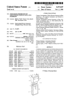
[57]
ABSTRACT
In a communication system comprising different appara
tuses which are coupled together by a bus, a control instruc
tion, for example, a remote control command may be passed
on by a plurality of apparatuses to the apparatus performing
the instruction. In order that the apparatus performs such an
345/169; 348/734
Field of Search .......................... .. 364/138; 358/194;
345/158; 395/375
[561
European Pat. 01f. .
(The D2B Concept) Of The User Manual Of Single-Chip
[63] dcgr‘l‘gf‘ijgi‘gg i‘faieorr-mlzgéégg?gslérl‘l?f$91k???
[58]
340/825.22
. . . . . . . .. 345/158
0165600
2900380
_
Apr. 2, 1991
Ikezaki . . . . . . .
0137225
Related US. Application Data
_
11/1994
370/85 1
370/851
359/118
FOREIGN PATENT DOCUMENTS
0071296 2/1983 European Pat. Off. _
Y
Appl. No.: 483,629
[22] Flledi
[30]
Nov. 26, 1996
METHOD AND APPARATUS FOR
CONNECTED To A
[21]
5 ,579,496
References Cited
instruction only once, the control circuit in the apparatus
U.S. PATENT DOCUMENTS
memorizes from which source the performed instruction has
3,947,849
3/1976 Fehlmeret a1. ...................... .. 342/389
been recewed- The ldenucal 901ml msmlcuons recelved
4 040 031
4,209,838
8/1977 Cassomet ________ __
6/1980 Alcom, Jr. et a1. .
from the other apparatuses are ignored for a predetermined
Period of time
395/250
4,236,203
11/1980 Curley et a1. 1
4,482,947
11/ 1984 Zato et a1. ............................ .. 364/138
8 Claims, 4 Drawing Sheets
/l
INTERFACE
INTERFACE
MONITOR
[3' cmcun \
r
S
~22
1
L
\
(
4*»12
l
94-21
»—~- L2
l HM/MICROPROCESSOR
944- 1.1
A~-31
/
l
AUDIO /
AMPLIFIER
,~vmEo
\
MlliROPROCESSOR
33
I
V K INFRARED/ V
RECElVER//
A
1: 1:1 I: ,5
1: 1:1 1:1
1:! U :1
1:1
L3 RECORDER
US. Patent
Nov. 26, 1996
Sheet 1 0f 4
/
INTERFACE
CIRCUIT \
5,579,496
1
INTERFACE
2
MONITOR
3 CIRCUIT \
5
AFN-22
?~32
L
»~~ 1.2
/—MlCROPROCESSOR
Z1
f~~31
—— L1
I
Ar~~33
J
Aumo/
AMPLIFIER
\
1
MRCROPROCESSOR V KINFRARED/ V
RECEIVEW
1:11:10 ,5
1:11:10
nun
US. Patent
Nov. 26, 1996
ULDEM 1:0
ULDMA 1:0
i :0
0LDEM1=CM “59
ULIJMA :=MA
{i=0
Sheet 2 6f 4
H51
5,579,496
US. Patent
Nov. 26, 1996
Sheet 3 0f 4
5,57 9,496
Jr
if
FIGA
FIGS
35
LE
37
38
ll
'1
il
1
M3)
!%
"l1
1]
R (L)
FIG]
5,579,496
1
2
METHOD AND APPARATUS FOR
PROCESSING CONTROL INSTRUCTIONS
RECEIVED FROM MULTIPLE SOURCES
CONNECTED TO A COMMUNICATION BUS
apparatuses and will carry out the two instructions. The
result is that the volume is raised by two steps, which may
generally not have been the user’s intention. If the user
keeps the “volume up” key on the infrared hand-held remote
control unit depressed, this operating command is generated
in a repetitive manner and both apparatuses will pass on the
corresponding control instruction also in a repetitive manner
to the audio ampli?er. The volume will now be raised twice
faster than is desirable.
Apparatuses passing on a control instruction to another
This is a continuation of application Ser. No. 08/209,681,
?led Mar. 10, 1994, which is a continuation of application
Ser. No. 07/853,366, ?led on Mar. 18, 1992, both now
abandoned.
connected apparatus via the D2B bus will hereinafter be
BACKGROUND OF THE INVENTION
referred to as sources. The apparatus for which these control
instructions are intended is provided with a control circuit
The invention relates to a method of processing control
instructions received from at least two identi?able sources
receiving and processing the control instructions. It is to be
used, inter alia, in apparatuses which are coupled together by
noted that the control circuit can identify the source of a
control instruction. For this purpose, and as indicated in the
use of a bus. These may be audio and video apparatuses, but
Reference, each “D2B message” on the bus does not only
aim, for example washing machines, microwave ovens,
include the control instruction and a “slave address” (with
which the apparatus is addressed) ‘but also a “master
address” which identi?es the source of the message.
via a communication connection. Such a method can be
luminaires and the like.
The invention also relates to an apparatus provided with
a control circuit adapted to perform the method.
Lately, apparatuses have been provided with a connection
20
SUMMARY OF THE INVENTION
for coupling them to a common bus. By use of this bus a
plurality of apparatuses can be operated from one point in
25
the house. It is also possible to transmit all kinds of control
instructions from each apparatus to any other apparatus
which is connected. An example of such a bus is known
under the name of Domestic Digital Bus (frequently abbre
viated to D2B bus) which is described, for example, in
instructions which have been received more than once.
To this end the method according to the invention is
characterized in that, upon execution of a control instruction,
an instruction code corresponding to the executed control
instruction and a source code corresponding to the source
chapter 11 (The D2B Concept) of the User Manual of
thereof are stored upon reception of a control instruction, an
Single-Chip 8-bit Microcontrollers, published by Philips
instruction code corresponding to the received control
instruction is compared with the stored instruction code, and
Electronic Components and Materials, 1986. The D2B bus
provides easy operation of, for example, an audio/video
system including a plurality of apparatuses. For example, a
35
video recorder may automatically switch on a television
receiver and tune this receiver to the correct video recorder
channel when a video tape is to be displayed.
Apparatuses having a D2B connection will often also
have their own infrared receiver so that they can also be used 40
as stand-alone apparatuses. Such apparatuses may be imple
mented in such a way that a control instruction which has
been received by the infrared receiver and cannot be carried
out by the apparatus itself is passed on via the D2B bus to
an apparatus which does have the required facilities. The
latter apparatus then need not have an infrared receiver of its
It is an object of the invention to provide a method
preventing the unwanted consequences of identical control
if they match the source code corresponding to the source of
the received control instruction is determined and checked
whether the source code matches the stored source code. The
execution of the received control instruction is omitted if the
source code does not match the stored source code. It is
thereby achieved that from a series of identical control
instructions from different sources only the instruction is
carried out from the source whose source code was already
stored. The control instructions from the other sources are
redundant and are ignored. If repetitive control instructions
45
are received, only the instructions from the one and the same
source is carded out.
A further embodiment of the method is characterized in
that execution of the received control instruction is omitted
apparatuses having theft own infrared receivers are coupled
if also less than a predetermined period of time has elapsed
together via the D2B bus, a problem arises which will now
be illustrated with reference to an example. An audio/video 50 since the reception of the control instruction executed
before. In that case the control instruction from the trans
system comprises a video recorder, a television monitor and
mitter whose control instruction is received ?rst after the
an audio ampli?er with loudspeakers. The video recorder,
predetermined period of time has elapsed will be performed.
provided with an infrared receiver, receives the operating
Another embodiment of the method is characterized in
command “volume up” from an infrared transmitter for
increasing the sound volume by one step, but it cannot carry 55 that the source code corresponding to the source of the
received control instruction is also stored if the execution of
out this command itself because it lacks a built-in audio
the control instruction is omitted and in that the source codes
ampli?er section. The same applies to the television monitor
corresponding to the other sources are erased when the
which is also provided with an infrared receiver. In a
control instruction is being executed. The effect achieved
previously performed installation phase both apparatuses
have been programmed to pass on control instructions 60 thereby will be explained with reference to an example. Let
it be assumed that of a series of identical control instructions
relating to sound functions via the D2B bus to the audio
from different transmitters the instruction from transmitter A
ampli?er accommodated in a cabinet. The apparatuses will
is executed and the instruction from transmitter B is ignored.
attempt to do this simultaneously or substantially simulta
It is now possible that the instruction from transmitter A is
neously. In response to an arbitration procedure described in
the Reference the two instructions will be passed on to the 65 absent in a subsequent series of control instructions, for
example, because the infrared receiver of the corresponding
audio ampli?er one after the other. The audio ampli?er now
apparatus was temporarily covered. It is also possible that
receives the control instruction “volume up” from both
own, or it may be accommodated in a closed space. If more
5,579,496
3
4
the control instruction from transmitter A in the subsequent
series is received later than the control instruction from
transmitter B, for example, because transmitterA has lost the
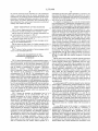
transmitter and the slave station operates as a receiver. The
data ?elds 16 comprise 8 bits each and indicate the control
instruction to be transmitted. Each data ?eld is terminated by
previously mentioned arbitration procedure. Of the subse
a bit (not shown) indicating whether the corresponding data
quent series, the control instruction from transmitter B is
now performed. Thus, each control instruction is performed
?eld is the last of the message.
actually and without any delay.
bus simultaneously or substantially simultaneously, an arbi
tration procedure will be carried out. Brie?y summarized,
the substance of this procedure is that during the transmis
If a plurality of apparatuses is to use the communication
BRIEF DESCRIPTION OF THE DRAWINGS
10
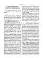
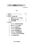
FIG. 1 shows diagrammatically a communication system
in which the method according to the invention is used.
FIG. 2 shows the structure of a message transmitted via
the communication bus shown in FIG. 1.
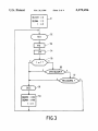
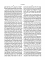
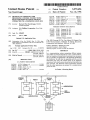
FIG. 3 shows a ?ow chart of a control program performed
by a control circuit shown in FIG. 1.
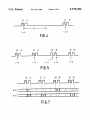
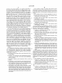
FIGS. 4 and 5 show examples of some messages occur
ring on the communication bus.
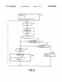
FIG. 6 shows the ?ow chart of a further example of the
15
control program performed by the control circuit shown in
FIG. 1.
FIG. 7 shows a further example of some messages which
occur on the communication bus.
25
DETAILED DESCRIPTION OF THE
PREFERRED EMBODIMENTS OF THE
INVENTION
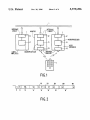
FIG. 1 shows diagrammatically a communication system.
The system includes a communication bus 1 for transmitting
control instructions. In this case three apparatuses 2, 3 and
station will withdraw. The arbitration procedure results in
only one master station being active after the master address
has been transmitted. Other master stations will wait until
the end of the message and at a later stage they will make
another attempt to use the bus. The remaining master station
now transmits the slave address 14 of the apparatus for
which a control instruction is intended. As is shown in FIG.
2, the slave address comprises a space 14 1. If a slave station
recognizes its own address, it will transmit an acknowledge
bit A in this space. If the master station does not detect this
bit A, it means that the slave station is not present or does
not function. The message is then immediately ended. In a
corresponding way the slave station transmits an acknowl
edge bit in a space 151 after recognition of the control ?eld
15 and in a space 161 after correct reception of each data
?eld 16.
FIG. 3 shows a ?ow chart of a control program performed
by the microprocessor in each apparatus. In a step 51 of this
control program, which step is performed when the appa
ratus is switched on, an initial value is assigned to a number
4 are connected to this communication bus. The apparatuses
may be simple or complicated, for example, a television
apparatus, a recorder, a washing machine, a microwave 35
oven, a lurninaire, a sensor for the outside temperature, etc.
The function of the apparatus is controlled by a local
microprocessor 21, 31 and 41. The microprocessor com
prises in further known manner a ROM for storing a control
program and a RAM for storing variable dam. For receiving
control instructions from other apparatuses and for trans
mitting control instructions to other apparatuses, the micro
processor in each apparatus is coupled to the communication
bus 1 by an interface circuit 22, 32 and 42. Such an interface
40
circuit is, for example, the integrated circuit SAxl235 of the
?rm of Philips. In the apparatuses 3 and 4 the microproces
45
of variables in the RAM of the microprocessor. An instruc
tion code OLDCM is intended to keep a record of the last
control instruction performed by the apparatus. A source
code OLDMA is intended to keep a record of the apparatus
from which the last performed control instruction was
received. In the initial step 51 the two variables acquire a
pseudo-value, for example, the value of zero so as to indicate
that no control instructions have been received yet. A
counter t has the initial value of zero. This counter represents
an elapsed time which is autonomically increased by the
microprocessor.
sor is also coupled to an infrared receiver 33 and 43 for
receiving operating commands which are generated by a
remote control unit 5.
FIG. 2 shows the structure an information level of a 50
message transmitted via the communication bus. For a
detailed description at bit level, reference is made to the
sion of the start bit, the mode ?eld and the master address a
master station checks whether each transmitted bit is actu
ally put on the bus. If this is not the case, the relevant master
In a sub-program RCV, which is denoted by the reference
numeral 52, it is subsequently checked whether the appara
tus is addressed by one of the other apparatuses via the
communication bus. As previously noted, the slave address
(14 in FIG. 2) is to this end compared with the own address
of the apparatus and in the case of recognition the acknowl—
edge bit A is transmitted. Subsequently, in a step 53, the
received master address (13in FIG. 2) is stored in a variable
which will be denoted by MA. Finally, the data ?elds (16 in
FIG. 2) are read in a step 54. These data ?elds constitute the
actual control instruction which must be carried out by the
shown in FIG. 2 comprises a start bit 11, a mode ?eld 12, a
master address 13, a slave address 14, a control ?eld 15 and 55 addressed apparatus. The control instruction thus received is
provisionally stored in a variable which will be denoted by
one or more data ?elds 16. The mode ?eld 12 indicates the
CM.
bit rate with which the message is transmitted. The master
In a step 55 the count of the counter t is compared with
address 13 comprises 12 bits and identi?es the apparatus at
a predetermined value T. If the value of t exceeds T, a
whose initiative the message is transmitted. This apparatus
is referred to as the master station. The slave address 14 also 60 predetemiined period of time, for example, 1 second has
Reference stated in the opening paragraph. The message
comprises 12 bits and indicates the addressed apparatus.
elapsed and a sub-program 58 is performed. The sub
program 58 comprises the actual performance of the control
This apparatus is referred to a slave station. The control ?eld
instruction and is separately speci?ed for each apparatus.
15 describes the nature of the message and indicates, inter
Subsequently, the step 59 is performed. In this step a value
alia, whether the message comprises a read or a write
operation. It is to be noted that the master station and the 65 which is representative of the performed control instruction
slave station can both transmit and receive. It will herein
is assigned to the instruction code OLDCM. Moreover, the
master address MA, which identi?es the transmitter of the
after be assumed that the master station operates as a
5,579,496
5
6
control instruction, is stored in the source code OLDMA.
Finally, the value of zero is assigned to the counter t.
Thereafter the control program returns to the sub-program
received by the audio ampli?er. The Figure shows that the
52 to check whether more control instructions are received.
from the video recorder. As is shown in a shaded form in the
Figure, the control instructions 36-39 from the monitor are
monitor wins the arbitration, except in the case of control
instruction 38 which is preceded by control instruction 48
If it has been determined in the step 55 that the prede
termined period of time T has not elapsed yet when a control
instruction is received, it is checked in a step 56 whether the
received control instruction CM is equal to the previously
invariably performed. This also applies to the control
instruction 38. The corresponding control instruction 48
from the video recorder is ignored because the predeter
mined period of time T has not elapsed yet upon its
executed control instruction OLDCM. If this is not the case,
the control instruction in the subprogram 58 is executed. If 10 reception.
the two control instructions are equal, it is checked in a step
FIG. 6 shows the ?ow chart of another example of the
57 whether both of them have been transmitted by the same
control program. In this Figure identical reference numerals
apparatus. To this end the master address MA in the received
denote the same elements as in FIG. 3. Characteristic of the
message is compared in the step 57 with the master address
example of the control program shown in FIG. 6 is the
of the previously performed instruction stored in the source
presence of an array R in the RAM of the microprocessor.
code OLDMA. If the two addresses are equal, the control
The array R_stores a source code for each apparatus with the
instruction is executed. However, if the control instruction
master address i in the form of an array element R(i) which
originates from another apparatus, the instruction will not be
can assume the logic value “0” or “1”. In the course of the
carried out.
control program the logic value R(i)=“0” means that control
The control program described hereinbefore will now be
instructions have not yet been received from the correspond
used in the communication system shown in FIG. 1. To this
ing apparatus with master address i.
end it is assumed that apparatus 2 in FIG. 1 is an audio
An initial step 511, in which, as previously described, a
ampli?er, apparatus 3 is a television monitor and apparatus
pseudo-value is assigned to the instruction code OLDCM
4 is a video recorder. The monitor 3 and the video recorder
4 receive an infrared command “volume up” from the 25 and the value of zero is assigned to the counter t is performed
by the control program. Moreover, in the step 511 the logic
remote control unit 5. They cannot carry out this command
value of zero is assigned to all source codes R(i) so as to
themselves and have been programmed in a previously
indicate
that control instructions have not been received yet.
performed installation phase to pass on sound control com
Subsequently, a message is received in a manner already
mands to the audio ampli?er 2 via the communication bus 1.
described in the sub-program 52, the master address MA of
FIG. 4 diagrammatically shows in a time sequence the
the source of this message is determined in the step 53 and
the control instruction CM is read in the step 54. If the
messages which occur at the communication bus in response
to the “volume up” command. More particularly, FIG. 4
shows a control instruction 34 from monitor 3 to ampli?er
control instruction is actually executed in the sub-program
58, a step 591 is subsequently performed. In this step the
2 and a control instruction 44 from video recorder 4 to
current instruction CM is stored in the instruction code
OLDCM and the counter is set to zero. More particularly, all
ampli?er 2. As has been shown in the Figure, the control
instruction 34 is the ?rst to be transmitted because monitor
source codes R(i) acquire the logic value “0” again after a
3 has won the arbitration procedure. Both control instruc
control
instruction has been executed, except for the source
tions indicate that the sound volume must be raised by one
code R(MA) which corresponds to the apparatus from which
step. The audio ampli?er will now execute control instruc
tion 34, which is shown in a shaded form in the Figure. The 40 the executed control instruction was received.
When a control instruction is received within a predeter
control instruction 44 is not carried out because it relates to
mined period of time (determined in step 55) after the
an identical control instruction which has been received
within the predetermined period of time T after the instruc
tion 34 has been carried out. The volume is therefore raised
by one step, which is in conformity with the “volume up”
command generated once. If the same command is generated
45
again some time later, the audio ampli?er will again receive
previous execution of the same instruction (determined in
step 56), step 571 is now performed. In this step 571 it is
checked whether the source code R(MA) has the logic value
“1”. If R(MA) has the logic value “0”, the control instruction
from the corresponding apparatus has not been received
two control instructions. In the Figure the new control
since the last execution. Such an instruction is not executed
instruction from the monitor is denoted by 35 and the new
control instruction from the video recorder is denoted by 45.
As indicated in FIG. 4, the video recorder won the arbitra
tion procedure, so the audio ampli?er will receive the
control instruction 45 ?rst. Now, the audio ampli?er will
perform the control instruction 45 from the video recorder,
which instruction is shaded in the Figure. The control
instruction 35 from the monitor is now ignored. The sound
volume is again raised by not more than one step.
FIG. 5 diagrammatically shows in a time sequence the
because the instruction originating from another apparatus
has “just” been performed, namely from the apparatus for
which currently the source code R(i)=1. In a step 572 the
value “1” is assigned to the source code R(MA) so as to
establish that the control instruction has been received from
this apparatus.
If it has been detemiined in the step 571 that R(MA) has
the value “1”, this may have two causes. On the one hand,
messages which occur on the communication bus if the
“volume up” key on the remote control unit 5 (see FIG. 1)
is kept depressed. In this situation the “volume up” com
mand is generated in a repetitive manner with intervals of
approximately 100—150 ms. In FIG. 5 the corresponding
control instructions from the monitor are denoted by 36—39
60
the control instruction may originate from the apparatus
whose previous instruction was performed. On the other
hand, the control instruction may originate from an appara
tus whose previous instruction was received but ignored. In
both cases the control instruction is executed now.
and the control instructions from the video recorder are 65
FIG. 7 again shows diagrammatically in a time sequence
the repetitive messages occurring on the communication bus
if the “volume up” key on the remote control unit 5 (see FIG.
1) is kept depressed. To explain this Figure, the values of the
denoted by 46-49. It always depends on the result of the
arbitration procedure which instruction is the ?rst to be
corresponds to monitor 3 and R(4) corresponds to video
source codes R(3) and R(4) are plotted on the time axis. R(3)
5,579,496
7
8
recorder 4. In contrast to FIG. 5, it is apparent from FIG. 7
2. The method of claim 1, wherein said second control
instruction is executed if the elapsed time between reception
of said ?rst control instruction and reception of said second
control instruction is at least equal to a predetermined period
that control instruction 48 from the video recorder is now
executed and that the control instruction 38 from the monitor
is ignored. This is accomplished by step 571 of the control
program (see FIG. 6). In this step the source code R(4) is 5 of time.
detected to have the value “1” when the control instruction
3. The method of claim 1 further comprising the steps of:
48 is received, which is caused by the fact that a control
instruction 47 has already been received before (but not
executed at that time) from the video recorder. The audio
ampli?er thus switches, as it were, temporarily from execu 10
tion of control instructions from monitor 3 to execution of
control instructions from video recorder 4. This is particu
larly sensible if there were circumstances which would lead
to the absence of the control instruction 38. The control
instruction 48 from the video recorder is thus executed if the 15
control instruction 38 from the monitor is absent, for
example, because the corresponding “volume up” command
from the remote control unit has not reached the monitor due
to a temporary interruption of the infrared light ray.
It is to be noted that the use of the method according to
the invention is not limited to communication systems with
a common communication bus. For example, an apparatus
may also receive the control instructions from other appa
f) storing said second source code if said second control
instruction is not executed; and
g) erasing said ?rst source code if said second control
instruction is executed.
4. The method of claim 2, further comprising the steps of:
f) storing said second source code if said second control
instruction is not executed; and
g) erasing said ?rst source code if said second control
instruction is executed.
5. An apparatus for processing a plurality of control
instructions for controlling the apparatus received from at
least two sources which are coupled to a communication
connection, said apparatus comprising:
a) means for receiving and executing a ?rst control
instruction from a ?rst source;
b) means for storing a ?rst instruction code representing
ratuses via individual connections. In that case a transmit
said ?rst control instruction and a ?rst source code
ting apparatus is not identi?ed by a master address which is
comprised in a received message, but by the physical
location of the connection through which the control instruc
identifying said ?rst source;
0) means for receiving a second control instruction from
tions are applied. It is also to be noted that not all sources
have to be external apparatuses. For example, one of the
sources may be accommodated in the apparatus itself and 30
function as a sub-apparatus within this apparatus. An infra
red receiver built in an apparatus constitutes a sub-device
d) means for comparing a second instruction code repre
senting said second control instruction to said ?rst
instruction code and, comparing a second source code
Such an internal source is not identi?ed by the master 35
address of the apparatus but by a sub-device address which
is incorporated in the data ?elds of a B2B message.
I claim:
1. A method for processing a plurality of control instruc
tions received from at least two sources which are coupled
to a communication connection, the control instruction
being intended for controlling an apparatus and said method
comprising the steps of:
a) receiving and executing a ?rst control instruction from
control instruction and reception of said second control
instruction and wherein said second control instruction is
executed if the elapsed time between reception of said ?rst
control instruction and reception of said second control
instruction is at least equal to a predetermined period of
time.
a ?rst source;
control instruction and a ?rst source code identifying
said ?rst source;
c) receiving a second control instruction from a second
7. The apparatus of claim 5, further comprising:
source;
d) comparing a second instruction code representing said
second control instruction to said ?rst instruction code
and, comparing a second source code identifying said
second source is di?erent than said ?rst source and said
second instruction code matches said ?rst instruction
code, and executing said second control instruction if
said second instruction code is different than said ?rst
instruction code or said second source is the same as the
?rst source.
e) means for disregarding execution of said second con
trol instruction if said second source code differs from
said ?rst source code and said second instruction code
matches said ?rst instruction code, and means for
executing said second control instruction if said second
instruction code is different than said ?rst instruction
code.
6. The apparatus of claim 5, further including means for
measuring the elapsed time between reception of said ?rst
b) storing a ?rst instruction code representing said ?rst
second source to said ?rst source code; and
corresponding to said second source to said ?rst source
code; and
within the B2B system whose control instructions are
equivalent to control instructions from external apparatuses.
e) disregarding said second control instruction if said
a second source;
55
o means for storing said second source code if said
second control instruction is not executed; and
g) means for erasing said ?rst source code if said second
control instruction is executed.
8. The apparatus as claimed in claim 6, further compris
ing:
f) means for storing said second source code if said
second control instruction is not executed; and
g) means for erasing said ?rst source code if said second
control instruction is executed.