1
ENGLISH
OTHERS
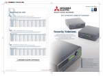
DIGITAL RECORDER
INSTALLATION MANUAL
MODEL
DX-TL308E
DX-TL304E
THIS INSTRUCTION MANUAL IS IMPORTANT TO YOU. PLEASE READ IT BEFORE USING YOUR DIGITAL RECORDER.
1
Before use
How to use this manual
About this manual
The manual of this recorder consists of the following two
manuals.
How to locate information in this manual
You can find desired information in this manual using the
following methods.
Table of contents
Reference page
Pages 5 to 7
Shown in the texts.
Installation Manual (this manual)
This manual describes connections of devices as well as
functional settings and operations to use this recorder.
This manual mainly describes operating procedures carried
out by the mouse.
User's Manual
When you first set up the recorder, you can configure the
minimum required settings using the Setup Wizard.
• Language setting
• Clock setting
This manual is for operators of this recorder and describes
the operating procedures for the basic functions only.
Symbols
Tips
How to locate setting items
(Reference for operation)
Shows information to be referred to when you operate this
recorder.
Notice (Point to be noted)
Shows information to be noted when you operate this
recorder.
(Reference page)
Shows the sections and pages to be referred to.
Troubleshooting
See "Troubleshooting" (
appropriate measures.
pages 125 to 127) and take
Note
The illustration in this manual shows an example of DXTL308E.
• HDD operation setting
• Recording setting
When you configure these settings manually or configure
other settings, find desired functions and pages describing
those functions using the following methods.
Search based on the function you want to use
See the table of contents (
pages 5 to 7).
Search for the setting method for the connected device
See the reference pages shown by the descriptions of
page 24).
the devices in "Connections" (
Search based on the items displayed on the screen
See the reference pages shown by the descriptions of
page 22).
the displayed items in "Screen display" (
Search from the quick menu list
You can find the setup menus and recording setting
menus as well as their setting items in the quick menu
pages 46 to 49 and pages 92 to 98.
lists on
In addition, you can find the factory default setting of
each setting item, too.
Using these lists, you can keep records of your settings
and review them later.
2
ENGLISH
Setup procedure
Start here when you first
set up the recorder.
1
Connect the recorder.
Connect the cameras, monitors, and sensors to the recorder. Configure the settings of the connected devices referring to the
reference pages shown in the descriptions of the devices in "Connections" on
page 24.
2
Turn on the recorder.
Turn on the main switch on the rear of the recorder. After checking the POWER indicator goes out, press the POWER button on
the front panel of the recorder.
3
Select whether or not to use the Setup Wizard.
When you turn on the recorder first time, the Setup Wizard is activated.
"Setup Wizard" on pages 32 and 33.
Using the Setup Wizard, you can set the following items automatically according to the displayed menus.
Language setting
The language used for the menu screen is selected.
Clock setting
HDD configuration
All the connected HDDs are registered as Main device. For details of the HDD configuration, see
pages 34 to 37.
Recording setting
The settings for normal recording are configured. For details of the recording, see
pages 44 to 55.
When using the
Setup Wizard
4-1
When not using the
Setup Wizard
Run the Setup Wizard.
Set the items shown above according to the displayed menus.
(To change the
settings made by
the Setup Wizard)
4-2
As
needed
4
Change the settings made by the
Setup Wizard.
To manually change the settings made by the Setup Wizard:
Language setting
Page 99
Clock setting
Page 99
HDD configuration
Pages 34 to 37
Recording setup
Pages 44 to 55
Make the minimum required
settings manually.
Page 99
Language setting
Clock setting
Page 99
HDD configuration
Pages 34 to 37
Recording setup
Pages 44 to 55
Start here when you change
the settings of the
recorder already set up.
5
As
needed
6
Make other settings.
How to search for necessary settings
Refer to "How to locate setting items" on the left
page, and find the pages describing the
functions and settings you want to use and
configure the necessary settings.
Make the necessary settings according to your desired recording operation.
For example,
To carry out timer recording. Timer program setting
pages 62 to 65
To use the mirroring mode. Mirroring setting
page 35
To control the recorder from the personal computer. Communication setting
pages 108 and 109
To control the camera. PTZ camera setting
page 110
To restrict the recorder's functions by the password lock. Password setting
pages 111 to 114
To make settings of screen display and rear terminals.
"Setup menu" on pages 92 to 110.
Check the setup condition.
By executing recording, playback, search, and copy, check that the recorder has been set up correctly.
Beginning
3
Major features
This digital recorder is able to record images captured by up to 8 (DX-TL308E)/4 (DX-TL304E) surveillance cameras and
audio received by microphone to its hard disk. The recorder is equipped with the function to search for desired scenes by
specifying the recording dates as well as the simultaneous recording/playback function that allows playback even during
recording. In addition, using the split display function to display up to 8 (DX-TL308E)/4 (DX-TL304E) camera images on one
screen, you can view more than one monitored area at the same time. This recorder facilitates to configure a monitoring
system for constant surveillance.
Realizing long-term recording
By reducing the size of recorded video data using the newly developed video compression engine (MEPG 4 system), the
writing capacity of HDD can be saved about 50% (compared with our conventional models). In addition, this recorder is
designed to connect external HDD to expand its HDD capacity up to 16 TB (when using optionally available DX-ZD6UE). Due
to this, you can construct a long-term recording system to store data for 2 years, for example.
Simple operation and USB mouse connectable
By connecting a separately available USB mouse to the serial bus terminal on the recorder, you can easily control the
recorder and setting menus. For frequently used functions such as search and copy, the simple operation menu allows you
to operate them by simple procedure. This recorder is equipped with the on-screen help function. By clicking the help icon or
pressing the HELP button, you can view various information such as operation procedures on the screen.
"One touch copy" for easy copying with one button press
The recorder is equipped with the function to copy still playback images to a USB memory device set in the recorder or a
disc in an external drive with one button press. You can select still images or moving images to copy. When selecting moving
images, you can specify the recording duration.
XGA output terminal integrated (DX-TL308E only)
You can connect a general PC display monitor to this terminal to use it as a surveillance monitor.
Motion detection search function
By designating certain areas such as doors and windows shown in recorded images as detection target areas, you can
search for recorded data containing scenes having variation (or motion) in those areas and display the beginning of such
data. This function is useful, for example, in searching for intruders into deserted places or scenes where someone painted
graffiti on the wall.
Personal information protection function
By setting passwords, you can classify the recorder operations into 3 levels. You can set a password for deleting data from
HDD to protect them from unauthorized access or to use this function as misuse prevention. The recorder is equipped with
the function to prohibit playback of data recorded before the number of days you specify (auto expiration setting), which
facilitates data management according to your operation standard regarding the data storage period.
Alarm notification of intrusion and system errors
When an alarm signal is input to the recorder from external body sensors or when an error is detected in the system,
the recorder notifies the designated personal computer via TCP/IP command or e-mail. The recorder is also capable of
transferring the alarm-recorded images that is triggered by an external alarm signal to the designated FTP server.
Microsoft is either registered trademarks or trademarks of Microsoft Corporation in the United States and/or other
countries.
All other company and product names appearing herein are the property of their respective owners.
4
Contents
Before use ...................................................................... 2
Registering the internal HDDs ...............................35
Mirroring ...........................................................35
Registering external HDDs ....................................36
Checking the registered devices ............................37
How to use this manual ..............................................2
About this manual ....................................................2
Symbols ...................................................................2
Troubleshooting .......................................................2
Note ........................................................................2
How to locate information in this manual .................2
How to locate setting items ................................2
Setting the repeat recording and partition of Main
device <Main HDD setting> ......................................38
Setting the repeat recording...................................38
Setting the partition ................................................39
Setup procedure ............................................................ 3
Viewing images captured by the cameras.................. 40
Major features ................................................................ 4
Multiplexer function...................................................40
Single screen display .............................................40
Split screen display ................................................40
Sequential display ..................................................40
Switching Output A and B ......................................41
Operating the DIGITAL ZOOM button ....................41
Triplex playback .....................................................42
Contents ......................................................................... 5
Caution and care ........................................................... 8
Note .............................................................................. 15
Open source software ...............................................15
MPEG-4 patent ...........................................................15
Major operations and their functions ........................ 16
Front view ...................................................................16
Front view (inside of door) .......................................18
Rear view ....................................................................20
Screen display ...........................................................22
Connections
Viewing images
Controlling the cameras ............................................. 43
Controlling the cameras using the menus ..............43
Recording
Recording .................................................................... 44
Recording methods ...................................................44
Recording types.........................................................44
Connections ................................................................. 24
Before making recording settings ...........................45
Playback during recording .....................................45
Connecting CCTV cameras, monitors, and sensors
.........................................................................24
Procedure of configuration of recording settings ..46
Connection for alarm recording ...............................25
Cable clamping ..........................................................26
Connecting an analog VCR ......................................26
Optional products ......................................................27
Recommended products ..........................................27
Caution for connecting additional hard disk units
.........................................................................27
Menu settings/Device registration
How to set the menus ................................................. 28
Displaying the menus ...............................................28
Operating the menus .................................................29
Closing the menus ....................................................29
Using the mouse operation screen ..........................30
Using the Setup Wizard .............................................. 32
Making the minimum required settings automatically
<Setup Wizard>.......................................................32
Registering the devices .............................................. 34
Setting Main, Copy, and Archive devices
<HDD registration> ................................................ 34
Cautions for using external devices .................34
Hookup and operation setting of HDDs ............34
Order of recording and playback of the internal
and external HDDs registered as Main device
....................................................................34
ENGLISH
Beginning
Making recording settings automatically <Auto setting>
.........................................................................50
Camera check ..................................................50
Define the normal recording cycle ....................50
Confirm the recording settings .........................50
Apply new settings ...........................................50
Making recording settings manually <Manual setting>
.........................................................................51
Recording A to D ....................................................51
Picture size .......................................................51
Picture quality and FPS ....................................52
Alarm camera setting .......................................53
Alarm input/output ............................................54
Supplementary explanations on recording settings
....................................................................54
Supplementary explanations on preliminary
recording .....................................................55
Emergency recording settings <EMR recording> ............56
Supplementary explanations on emergency
recording .....................................................57
Motion detection settings <Motion detection> ..................58
Cautions on motion detection setting ...............59
Audio recording settings <Audio recording> ....................60
Stopping alarm input .................................................61
Manual recording .......................................................61
Before starting manual recording .....................61
Beginning
5
Contents (continued)
Timer recording settings <Timer program> ......................62
When timer programs overlap ..........................65
Playback
Playback ....................................................................... 66
Selecting the playback device <Device selection> ...........66
Playing back recorded data ......................................66
Search
Searching for images you want to view .................... 68
Searching for the oldest recorded data
<Start point search> ..................................................68
Searching for the latest recorded data
<End point search> ...................................................68
Setting the searching conditions .............................69
Searching images based on the designated
data and time <Time date search> ..........................70
Searching from the alarm list <Alarm list search> ............70
Copying images registered in the alarm list .....71
Searching for images with motion <MD search> ..........72
Searching for images using various playback functions .. 73
Forward/rewind playback .......................................73
Frame-by-frame playback ......................................73
Reverse playback ..................................................73
Changing the playback rate ...................................73
Playing back the latest recorded image .................73
Caution in various playback functions ..............73
Searching for bookmarked images ........................... 74
Registering a bookmark ............................................74
Searching for bookmarked images ..........................74
Copy
Copying recorded data ............................................... 75
One-touch copy .........................................................75
Copying data by specifying the copy range ...........75
Setting the copy conditions ....................................75
Copying data by specifying the start time and
data size ...........................................................76
Copying data by specifying the end time and
data size ...........................................................76
Copying data by specifying the start time and
end time ...........................................................77
Caution in copying data ....................................77
Archiving data ............................................................78
Copying data from the recorded to videotape ........79
Communication
Using the communication functions ......................... 80
Communication functions of this recorder .............80
Restrictions on network users ................................80
Bandwidth control ..................................................80
Cautions in communicating by the Web browser or
PC viewing/communication software ...............80
Cautions regarding the same setting items
displayed on multiple screens ..........................80
6
Communication by Web browser .............................80
PC system requirements........................................80
Connections ...........................................................81
Login .....................................................................81
Notes on the Main Menu ..................................81
Viewing live images ...............................................82
Playing back recorded images ...............................83
Searching recorded images ...................................83
Searching for images by designating date and
time .............................................................83
Searching for images using the alarm list ........83
Setting the Main Menu ...........................................84
Changing user settings .....................................84
Setting the titles of the recorder and cameras ..85
E-mail setup......................................................86
FTP notification setup .......................................88
Connection mode setup ...................................89
Clock setup .......................................................90
Logout ....................................................................90
E-mail notification......................................................91
FTP notification ..........................................................91
Communication by the viewing/communication
software ..........................................................91
Others
Various settings ........................................................... 92
How to display the Setup menu .............................92
Quick reference chart for the Setup menu .............92
How to use the quick reference chart for the
Setup menu ................................................92
Settings of the present time and menu language
<Clock and language> ...............................................99
Clock setting .....................................................99
Language setting ..............................................99
Settings related to the warning display and rear
terminals <Warning display · EXT terminal setting> .........99
Warning display · Buzzer · Call-out 1 .....................99
Remain .............................................................99
Button sound ..................................................100
Start alarm recording ......................................100
Communication ..............................................100
Warning display • Buzzer • Call-out 2 ..................100
Mode-out • Remaining capacity ...........................101
Mode-out 1 and 2 ...........................................101
Remain 1 and 2 ..............................................101
Event terminal ......................................................102
On-screen display settings <Information display setting>
.......................................................................102
Clock display mode and location .........................102
Recorder status and title display ..........................102
Camera number and title display .........................103
Use the transparent menu ...................................103
Multiplexer settings <Multiplexer setting> ........................104
Output A/Output B ................................................104
Copy Output A settings ...................................104
4-split and 9-split ............................................104
Sequential display ..........................................104
Settings related to playback
<Setting the playback functions> ..................................105
Activate repeat playback ................................105
Display a playback image in field ...................106
Image originality check play ...........................106
Auto expiration on the specified date .............106
Settings related to the menus
<Loading/saving/initializing the menu settings> ..................107
Loading the menu settings .............................107
Save the menu settings ..................................107
Initialize the menu settings .............................107
Settings related to communication
<Communication setting> ..........................................108
RS-232C setting...................................................108
LAN setting .........................................................108
LAN service port settings ...............................108
E-mail notification - Address setting ...............108
IP alarm notification - Address setting ............109
FTP transmission settings ..............................109
PTZ camera setting..............................................110
Displaying the device information ........................... 118
Checking the registered devices and
recorded data area .......................................118
Displaying the <Device information> screen........118
Displaying the Main device information ...............118
Displaying the Copy device information ...............118
Displaying the Archive device information ...........118
Displaying the system log ........................................ 119
Displaying the system log ......................................119
Function against power failure ................................ 120
Power failure compensation circuit ......................120
Power failure recovery recording .........................120
Record of turning-off of the MAIN switch on the
rear panel .......................................................120
RESET button ......................................................120
Operation examples
Operation examples .................................................. 121
Operation example 1 ...............................................121
Operation example 2 ...............................................122
Operation example 3 ...............................................123
Troubleshooting
Restricting the operations of the recorder .................. 111
Troubleshooting ........................................................ 124
Simple lock ............................................................... 111
Enabling the simple lock ................................. 111
Disabling the simple lock ................................ 111
Checking the status of the recorder <Self-check function>
.......................................................................124
Password lock.......................................................... 111
Registering a password .......................................112
Enabling the password lock .................................112
Disabling the password lock ................................112
Password for restricting operations
(Levels 1 to 3) ...........................................112
Password lock for HDD protection .................113
Changing a password ..........................................113
Password for restricting operations
(Levels 1 to 3) ...........................................113
Password for HDD protection .........................113
Changing the lock mode from the password lock
to simple lock .................................................114
Changing the operation restriction level...............114
ENGLISH
Alarm display .......................................................104
Covert camera .....................................................105
XGA output (DX-TL308E only) .............................105
Error indications ......................................................128
Warning indication and call-out signal output ..128
Glossary/Specifications
Glossary ..................................................................... 132
Specifications ............................................................ 133
Protecting recorded data .......................................... 115
Protecting recorded data ........................................115
Checking the protected data ..................................115
Disabling data protection........................................115
Deleting recorded data ............................................. 116
Deleting recorded data ............................................116
Reducing the load on the HDD ................................. 117
Stopping the rotation of HDD that is not in use for
recording <HDD sleep mode> ...............................117
Beginning
7
Caution and care
HEAVY OBJECTS SHOULD NEVER BE PLACED ON THE UNIT (E.G., MONITOR)
NEVER TOUCH OR INSERT ANY OBJECT INSIDE THE UNIT
Touching the inside of the cabinet or inserting foreign objects of any kind through ventilation holes not only creates a safety
hazard but can also cause extensive damage.
PROTECT THE POWER CORD
Damage to the power cord may cause fire or shock hazard. If the power cord is damaged, turn OFF the MAIN switch and
carefully unplug the cord by holding the main plug.
If this unit is moved with the power on status, the built-in HDD may be damaged. Confirm that more than one minute have
passed since the power cord and the connecting cords were disconnected, then move this unit.
UNPLUG THE POWER CORD DURING A LONG ABSENCE
Turn off the power and unplug the power cord during a long absence.
MAINTAIN GOOD VENTILATION
Do not obstruct the many ventilation holes on the unit. For maximum ventilation, leave some space around the unit and place
the unit on a hard level surface only, and ensure it is not covered during use. Heavy objects should never be placed on the
unit.
WHEN NOT IN USE
When not in use, always turn OFF the MAIN switch.
CABINET CARE
Never use petroleum-based cleaners. Clean with a soft cloth moistened with soap and water and wipe dry.
PVC cables or leads should not be left in contact with the cabinet surface for long periods.
INSTALLATION LOCATION
For excellent performance and lasting reliability install in a location that is:1. Well ventilated, out of direct sunlight and away from direct heat.
2. A solid vibration-free surface.
3. Free from high humidity, excessive dust and away from magnetic fields.
4. Please ensure that the ventilation fan located on the unit’s back panel is not blocked.
UNSUITABLE LOCATIONS
Placing the unit in the following places might shorten the product life:
• Extremely cold places, such as refrigerated warehouses and ice houses
• Places where excessive hydrogen sulfide is likely to be generated, such as hot-springs areas
• Places or locations with salt air environment.
THIS EQUIPMENT DOES NOT PROVIDE CONNECTION FOR USED WITH OUTDOOR OR CABLE DISTRIBUTION
SYSTEMS.
NO OBJECTS FILLED WITH LIQUIDS, SUCH AS VASES, SHALL BE PLACED ON THE APPARATUS.
DO NOT PLACE HEAVY OBJECT ON THIS UNIT.
DO NOT STEP ONTO THIS UNIT.
The unit may drop or fall by losing its balance. It may cause injury or failure of the unit.
WARNING:
TO PREVENT FIRE OR SHOCK HAZARD, DO NOT EXPOSE THIS APPARATUS TO RAIN OR MOISTURE.
THIS APPARATUS MUST BE GROUNDED.
MAINS LEAD CONNECTION
The mains lead on this Unit is fitted with a non-rewireable mains plug, incorporating a 5A fuse. If you need to replace the
fuse, use a 5A fuse approved by BSI or ASTA to BS 1362, ensuring you refit the fuse cover. If the mains plug is not suitable for the sockets in your home, and you require to remove the plug, remove the fuse, cut off the plug then dispose of
the plug immediately, to avoid a possible electric shock hazard. To refit a new plug, follow these instructions; Green-andyellow: Earth, Blue: Neutral and Brown: Live. As the colours in the mains lead of this Unit may not correspond with the
coloured markings identifying the terminals in your plug, proceed as follows.
• The wire which is coloured green-and-yellow must be connected to the terminal in the plug which is marked by the
letter E or by the safety earth symbol or coloured green or green-and-yellow.
• The wire which is coloured blue must be connected to the terminal which is marked with the letter N or coloured
black.
• The wire which is coloured brown must be connected to the terminal which is marked with the letter L or coloured red.
8
ENGLISH
This unit complies with the requirements of the EC Directive 2004/108/EC, “EMC Directive” and 2006/95/EC, “Low Voltage Directive”. The requirements for the susceptibility according to EN 55024 and the requirements for interference according to EN 55022 are observed for the operation on residential areas, business, light industrial premises and in small
scale enterprises, inside as well as outside of the building. All places of operation are characterised by their connection
to the public low voltage power supply system. This unit is manufactured in accordance with EN 60950-1.
Warning
This is a class A product. In a domestic environment this product may cause radio interference in which case the user
may be required to take adequate measures.
Note: This symbol mark is for EU countries only.
This symbol mark is according to the directive 2002/96/EC Article 10 Information for users and Annex IV,
and/or to the directive 2006/66/EC Article 20 Information for end-users and Annex II.
Your MITSUBISHI ELECTRIC product is designed and manufactured with high quality materials and components which
can be recycled and/or reused.
This symbol means that electrical and electronic equipment, batteries and accumulators, at their end-of-life, should be
disposed of separately from your household waste.
If a chemical symbol is printed beneath the symbol shown above, this chemical symbol means that the battery or
accumulator contains a heavy metal at a certain concentration. This will be indicated as follows:
Hg: mercury (0,0005%), Cd: cadmium (0,002%), Pb: lead (0,004%)
In the European Union there are separate collection systems for used electrical and electronic products, batteries and
accumulators.
Please, dispose of this equipment, batteries and accumulators correctly at your local community waste collection/
recycling centre.
Please, help us to conserve the environment we live in!
About the hard disk drive (HDD)
• This unit is equipped with HDD, which is a very delicate device. Therefore, handle this unit carefully.
• Don't expose this unit to vibrations and shocks. It may be damaged when exposed to vibrations and shocks especially
during power-on or access to the HDD.
• Don't unplug the power cord during recording/playback or power-on.
• This unit is equipped with a system that automatically resumes and continues recording in the event of a minor failure
in the HDD or other components during recording. However, depending on the type of a failure in the HDD, this unit
may not able to continue recording. For early detection of failures, it is recommended to have this unit inspected every
year.
• In the event of a fault in the HDD, replace it immediately. For replacement of the HDD, please contact your Mitsubishi
dealer. (To replace the HDD, it is required to stop recording.)
• Use recommended HDD only. For HDD supported by this unit, please contact your Mitsubishi dealer.
• When the HDD is replaced, the recorded data are deleted. To ensure stable operation of this unit, the firmware may be
updated from time to time. The recorded data may be deleted in such a case.
• When you dispose of or transfer this unit, handle the video data stored in HDD carefully and take all responsibilities
related to the disposal or transfer.
• In the event of a failure in the HDD during normal recording or mirroring, this unit may not be able to resume recording
after rebooted, depending on the failure condition.
• When you enable the mirroring function while the recorded data are stored in the HDD, the recorded data are deleted.
• When you delete the data, the recorded images cannot be played back any more.
• It is recommended to check regularly that the recorded data are played back correctly.
Beginning
9
Caution and care (continued)
Installation location and handling
• Before you first use this unit, supply power to it for at least 48 hours to charge the built-in backup battery so that the
built-in power compensator circuit can be activated. When the battery isn't charged sufficiently, the built-in clock may
go wrong or the unit may not able to recover in case of a power failure.
• Don't plug this unit and high current devices (such as copier and air conditioning) into the same wall socket.
• Place this unit on a level and stable surface. When it is used on an unstable surface, a failure may be caused.
• Don't remove the outer covering of this unit.
• Don't place this unit close to other devices. They may interfere with each other, disturbing video and audio.
• Don't place this unit on a heat source. In addition, don't place this unit near a hear source because this unit has
ventilation openings in its sides and bottom. Otherwise the inside temperature may rise, causing a failure.
• When this unit is placed on or under the monitor, a failure may be caused, such as image disturbance.
• Don't place a strong magnetic object near this unit. It may affect the images adversely and cause loss of recorded
data.
• Don't expose this unit to volatile substances such as insecticide or don't leave this unit in contact with rubber or plastic
products for a long time. Otherwise the surface of the product may deteriorate or the coating may come off.
• When this unit is placed directly on the waxed floor, the adhesion may increase between the floor and the non-slip
rubber pads on the bottom of the product, causing the floor coating to come off or be colored.
• The HDD and cooling fans are motor-driven parts. To ensure stable recording, it is recommended to replace them
every 30,000 hours of use as a guide assuming that the ambient operating temperature is 25°C. When replacing HDD,
also replace the vibration-proof rubbers at the screwed areas. (Note that this period is just for a guide of replacement
interval and isn't intended to guarantee the lifetime of the parts. They may be broken earlier because of shocks applied
to the product and ambient operating temperature.)
• Be sure to use this unit within the allowable ambient temperature range (5° to 40°C) and humidity range (80% or less).
When you use the unit out of this temperature range, the internal parts may be adversely affected or a malfunction may
occur. In addition, when the temperature rises high, the characteristics of the HDD may deteriorate or its lifetime may
be shortened. When you use the unit in a low temperature environment, supply it with power for at least 10 minutes
before use.
• Clean the product regularly to prevent the ventilation openings from being covered by dust.
10
ENGLISH
Precautions for rack-mounting
• When mounting this unit in a rack, ensure that the temperature inside the rack doesn't rise to 40°C or higher. When
installing a rack, you are recommended to install fans to keep the temperature inside the rack 30°C or lower.
• Don't install a device that becomes hot under this unit. Otherwise the inside temperature may rise, causing a failure.
• Don't give a shock to all HDD devices in the rack.
• Before taking this unit in or out of the rack, be sure to turn off HDD devices being energized in the rack.
• Don't place this unit near a device that generates vibrations.
Changing installation location
• When moving this unit, be sure to turn off the MAIN switch, make sure that the unit is completely stopped, and then
unplug the power cord. When this unit is exposed to excessive shock while being energized, the internal electronic
parts or HDD may be damaged. Be careful especially while the power indicator or access indicator is blinking.
• Don't move this unit for at least one minute after you turn off the power. Even after the power is turned off, the disc
in the HDD keeps rotating by inertia for a while and the head is in an unstable state. This unit in such state is more
vulnerable to vibrations and shocks than while being energized. Be careful not to give this unit even a slight shock for
at least one minute after turning off the power. Wait at least one minute for the disc to stop, and then you can move the
product.
• When moving this unit, cover it with shock absorbers to prevent shocks to the inside.
• When placing this unit on a floor, lay it gently on a soft mat or cloth.
Maintenance
• Gently wipe dirt off the cabinet with a soft cloth.
• When dirt persists, clean it off using a cloth soaked in water-diluted neutral detergent and wrung well and then wipe
dry.
• When using a chemical cleaning cloth, follow its instructions.
• Don't use solvent such as benzene and thinner. Otherwise the surface of the product may deteriorate or the coating
may come off.
Beginning
11
Caution and care (continued)
Notes for constructing a surveillance system using this unit
• This unit can be controlled by external devices via the external connector, RS-232C connector, or LAN connector.
In addition, external devices can be controlled via the external connector, RS422 connector, or RS-232C connector.
These functions allow this unit to flexibly support an advanced security system. However, depending on the settings
of this unit or connection or combination with external devices, this unit or externally connected devices may operate
wrongly, causing adverse effects on the entire surveillance system.
• When constructing a surveillance system using this unit, you are recommended to check its operation by connecting or
combining it with other devices in advance.
• Don't use the alarm function of this unit for the purpose of making serious decisions or for applications involving human
lives.
• When this unit becomes unable to recognize an external device in recording because of a power failure, voltage drop,
or other failure, the recording point may move to the HDD inside this unit or other HDD. To prevent such symptom, it is
recommended to use an uninterrupted power supply or other similar device.
• When you unplug the power cord or turn off the breaker during recording, the HDD may be broken or recorded data
may become unable to be played back. When you turn on and off the breaker every day, program the timer recording
to be performed while the breaker is on and don't turn off the breaker during recording.
• When the user or any third party uses external devices wrongly, or external devices are affected by electric noise or
they are damaged or repaired, the saved data may be lost. Mitsubishi doesn't take any responsibility for damages
related to such data loss.
• By connecting various external HDDs to this unit, you can expand the memory or use them as a copy device. However,
when you perform recording, playback, or copy at a high rate using this unit, recording or playback data dropout or
other failure may occur depending on the connected device because of slow data transfer or slow response. Be sure to
check for such failure before starting the practical operation of the unit.
• Don't use the function to control the powers of external devices using the bus power of this unit.
• External devices you want to use may not be suitable for the intended application of this unit. For details, you are
recommended to contact your Mitsubishi dealer.
• When connecting external devices, be sure to secure the connected cables using the supplied clamp bands. When the
cables are disconnected or not connected firmly, the system may become unstable or images may not be recorded.
• Don't disconnect the cables while this unit is running. Otherwise a failure may be caused.
For important recordings
• Be sure to perform test recording before starting the practical operation of this unit, and also check regularly that the
recording is performed correctly according to the settings during the practical operation.
• Mitsubishi doesn't compensate for data not recorded or not played back correctly because of a failure occurring in this
unit or connected devices during the use of this unit.
• As a preparation for unexpected breakdown or accident, you are recommended to make regular backups of important
recordings. Though digital signals don't deteriorate, playback or recording may become impossible because of aging
deterioration of discs depending on the storage conditions.
12
ENGLISH
Copyright
• This unit records data digitally. Therefore, exercise caution in recording video images protected by copyright.
Recording time and product warranty
• Estimated recording time displayed on the menu screen is a continuous recordable time calculated in terms of the
functional operation, not a product warranty period. In addition, they are not a warranty period of the operational
reliability of the parts and components used in the unit.
Motion detection function
• Motion detection function in this unit may malfunction depending on the input condition of the video signal. If you
connect this unit to a system that issues an alarm using the motion detection function, take care to avoid such
malfunction. When the motion detection function malfunctions, connect another sensor to the ALARM IN terminal on
the rear of this unit.
Supplied power cord
• The supplied power cord is designed for this unit only. Don't use this cord for other products.
Network
• It is recommended to confirm with your network administrator about the network settings in advance.
• As this unit is operated through network, you may suffer from damage as follows.
(1) Leakage or drain of information through this unit.
(2) Unauthorized operation of this unit by malicious third parties.
(3) Disturbance or deactivation of this unit by malicious third parties.
To prevent damage listed above, take sufficient network security measures on your own responsibility.
• Set a network password that cannot be easily guessed by third parties. In addition, change the password regularly.
Beginning
13
Caution and care (continued)
Disclaimer
• Mitsubishi assumes no responsibility or makes no compensation for operation error of your surveillance system, loss
of recorded data, or other damages or losses due to a failure in this unit. In no event will Mitsubishi repair, restore, or
reproduce recorded data.
• In no event will Mitsubishi assume responsibility or liability for the following:
(1) Disassembly, repair, or alteration of this unit by the user or installer.
(2) Failure or breakdown in or damage to this unit resulting from misuse or careless handling by the user or installer.
(3) Inconvenience or damages resulting from inability to display or record images or to operate the unit's functions
correctly due to any reason or cause including breakdown or failure in this unit.
(4) Failure in this unit due to combination with other equipment manufactured by a third party, or inconvenience or
damages resulting from such failure.
(5) Inconvenience, damages, or claims arising out of breakdown in this unit or loss of recorded video data due to
replacement of the built-in HDD by the user or installer.
(6) Inconvenience or damages arising out of breakdown in this unit or inability to display or record images due to
natural disaster including earthquake and storm.
(7) Inconvenience, damages, or claims arising out of breakdown in the built-in HDD or loss of recorded video data due
to impact or vibration or environmental factors such as temperature at the installation site.
(8) Demand for damages or claim of infringement of privacy on the ground that the video monitored or recorded by
the user become public or are used for any purpose other than surveillance for whatever reason.
(9) Incidental, special, or consequential damages arising directly or indirectly related to this unit.
(10) Failure caused by any program created based on the command data provided by Mitsubishi, or inconvenience,
damages, or losses resulting from such failure.
• This unit is intended for recording and playback of video monitored by cameras. Mitsubishi doesn't assure that this unit
is capable of preventing crimes.
14
Note
ENGLISH
Open source software
Thank you for purchasing Mitsubishi digital recorder DX-TL308E/DX-TL304E (hereinafter referred to as “Product”). Before
using this Product, please be sure to read the Software License Agreement on page 11 of the user's manual with regard
to the software contained in this Product (hereinafter referred to as “Licensed Software”). By using this Product, you are
agreeing to be bound by the terms and conditions of the following Software License Agreement.
This Product contains software programs that are covered by GNU General Public License or GNU Lesser General Public
License. Such software programs are excluded from Licensed Software and not covered by the following Software License
Agreement. For the terms and conditions for use of the software programs covered by GNU General Public License or GNU
Lesser General Public License, please see “Notice about software to which GNU GPL/LGPL is applied”*.
In addition, this Product contains “Apache” and “OpenSSL (including “Original SSLeay” library).” These software programs
are also excluded from Licensed Software and not covered by the following Software License Agreement. For the terms and
conditions for use of these software programs, please see “Notice about Apache software”* and “Notice about OpenSSL software”*.
Other open source software contained in this product is excluded from Licensed Software and not covered by the following
Software License Agreement. For the terms and conditions for use of these software programs, please see “Notice about
other open source software”*.
*
The documents of “Notice about software to which GNU GPL/LGPL is applied,” “Notice about Apache software,” “Notice
about OpenSSL software,” and “Notice about other open source software” are contained (in the format of electronic
files as notice_GPL_LGPL_ja.pdf, notice_Apache_ja.pdf, notice_OpenSSL_ja.pdf, and notice_other_ja.pdf) in the
“OpenSoft_License” folder in the CD supplied with this Product.
MPEG-4 patent
This Product is licensed under the MPEG-4 pool license only for the purpose of personal and non-commercial use involving
the following activities:
(1) Encoding video in compliance with the MPEG-4 visual standard ("MPEG-4 Video").
(2) Decoding MPEG-4 Video that was encoded by a consumer engaged in a personal and non-commercial activity and/or
was obtained from a video provider licensed by MPEG LA to provide MPEG-4 Video. For more information, visit http://
www.mpegla.com.
(3) Playback of video recorded by the recorder using a personal computer in which the PC viewing/communication software
or the OCX software for Web browser is installed, or playback of video recorded by the recorder using a Web browser.
Beginning
15
Major operations and their functions
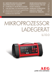
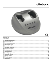
Front view
1
2
3
4
5
6
7
8
9
10
11
* This illustration shows an example of DX-TL308E
12
1
2
13
POWER indicator
OUTPUT A/B button
When the POWER button is pressed while the MAIN
switch on the rear of this recorder is ON, this indicator
illuminates. When this recorder is in the standby status
or the MAIN switch on the rear of this recorder is OFF,
this indicator goes out. It takes about 1 to 2 minutes
for this recorder to be ready for operation after the
POWER button is pressed. When this recorder is in the
process of operation transition such as startup, this indicator blinks and other operations are not acceptable.
When this button is held down for 2 seconds or longer,
the multiplexer output is switched between A and B.
The OUTPUT A/B indicator goes out when A is selected and it illuminates when B is selected. While the
multiplexer output B is selected, the menus are not
displayed.
6
Press these buttons to display images from the cameras connected to this recorder. The number of button
corresponds to that of the CAMERA IN connector on
the rear of this recorder. The button corresponding to
the camera you are viewing illuminates.
ACCESS indicators (HDD A, HDD B indicators)
This indicator illuminates when this recorder is accessing the internal HDD or externally connected devices.
Before pressing the POWER button, wait until the indicator goes out.
3
COM (COMMUNICATION) indicator
This indicator illuminates when this recorder starts
communicating via LAN.
4
OUTPUT A/B indicator
This indicator goes out when the multiplexer output A
is selected and it illuminates when B is selected.
5
SPLIT button
When this button is pressed, the screen mode changes
to split display mode.
16
<DX-TL308E> Camera number buttons (1 to 8)
<DX-TL304E> Camera number buttons (1 to 4)
Number buttons (0 to 9)
Press these buttons to input passwords.
7
SEQUENCE button
Press this button to automatically switch images from
cameras.
8
REC indicator
This indicator illuminates when this recorder starts recording. It goes out when the recorder stops recording.
9
ALARM REC indicator
This indicator blinks when this recorder starts alarm
recording. It goes out when the recorder stops alarm
recording.
ENGLISH
10 TIMER indicator
This indicator illuminates while this recorder is in the
timer recording mode or timer recording standby mode.
It blinks when an error is found in the timer program.
11 LOCK indicator
This indicator illuminates while the simple lock or the
password lock is enabled.
12 SERIAL BUS ports
Input and output ports to connect a device equipped
with serial bus terminal. Bus power cannot be used.
When the serial bus ports are not in use, attach the
serial bus port covers to keep dust from entering the
recorder.
13 ALERT indicator
This indicator blinks when the recorder notifies an important event such as an error occurring in it.
Beginning
17
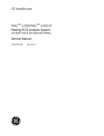
Major operations and their functions (continued)
Front view (inside of door)
14
15
16
17
25
26
18
19
20
21
27
22
23
24
28
* This illustration shows an example of DX-TL308E.
14 POWER button
The power is turned on when this button is pressed
while the MAIN switch on the rear is ON. When this
button is pressed again, this recorder enters the
standby mode. When this recorder is in the process of
operation transition such as startup, the POWER indicator blinks and other operations are not acceptable.
15 Analog output connectors
VIDEO OUT connector
RCA connector to output video signals. The same image as that from OUTPUT A is output.
AUDIO OUTPUT connector
RCA connector to output audio signals.
16 SET UP button
When this button is pressed, <Main menu> is displayed.
17 EXIT/CANCEL button
This button is used to set the menus.
18 Direction buttons (UP, DOWN, LEFT, RIGHT
buttons)
Use these buttons to move the item to be set during
menu setting.
These buttons are also used to move the magnification
center point while enlarging an image.
FRAME buttons
Use these buttons for frame-by-frame playback.
18
REW, FF buttons
Use these buttons to adjust the playback speed, and to
rewind or forward the recorded images.
ENTER button
This button is used to designate the detection target
areas of the motion detection function.
It is also used to accept the menu settings.
19 NEXT/START button
This button is used to set the menus.
20 BOOK MARK button
When this button is pressed, <Bookmark menu> is
displayed. When the playback device is designated
as Copy device, Archive device, or preliminary area,
Page 74)
<Bookmark menu> is not displayed. (
21 TRIPLEX PB button
When this button is pressed while live images from
cameras are being displayed in the split display mode,
the playback image of your desired camera is displayed. Triplex playback is possible with Output A only.
DIGITAL ZOOM button
When this button is pressed in the single screen display mode or the single screen playback mode, the
displayed image is enlarged. To move the magnification center point, press the direction buttons.
When this button is pressed, this recorder starts recording and the REC indicator illuminates. When this
button is held down for 2 seconds or longer, this recorder stops recording and the REC indicator goes out.
When this button is held down for 2 seconds or longer
during alarm recording or emergency recording, this
recorder stops recording. This recorder does not stop
recording during timer recording even when this button
is held down.
REV.PLAY button
When this button is pressed, this recorder starts reverse playback and the button illuminates.
ENGLISH
22 REC/STOP button
PLAY button
When this button is pressed, this recorder starts playback and the button illuminates.
SPEED (+ and -) buttons
When the playback (+) button or reverse playback (-)
button is pressed during playback or reverse playback,
the playback rate is changed.
23 TIMER button
When this button is pressed, this recorder enters the
timer recording mode or standby mode and the TIMER
indicator illuminates. When this button is held down
for 2 seconds or longer, the timer recording mode or
standby mode is canceled and the TIMER indicator
goes out.
24 LOCK button
When this button is pressed while the MAIN switch on
the rear is ON, this recorder enters the simple lock or
password lock mode. While this recorder is locked,
the indicator illuminates. You can set passwords using
<Password> of <Main menu>. (
Pages 111 to 114)
25 COPY button
When this button is pressed, <Copy menu> is displayed. Use this button to copy or archive data.
Pages 75 to 78)
(
This button illuminates during copy. It blinks at the start
and end of copy operation.
26 SEARCH button
When this button is pressed, <Search menu> is disPages
played. Use this button to search images. (
68 to 72)
27 HELP button
When this button is pressed, the help menu showing
information such as cautions on use, operating procedures, and functional descriptions is displayed.
It is also used to display the warning.
WARNING RESET button
When this button is pressed while a warning is displayed, the warning display is cleared.
28 Operation buttons
STOP button
Press this button to stop playback.
PAUSE/JUMP TO END button
When this button is pressed during playback, still image playback starts and the button illuminates. When
this button is pressed again, playback starts and the
button goes out.
When the PAUSE/JUMP TO END button is pressed
while the playback is stopped, images around the end
of the latest recorded data are played back in the still
image playback mode. (End point search)
Beginning
19
Major operations and their functions (continued)
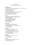
Rear view
1
2
4
5
6
7
8
9
3
10
11
12
13 14 15
* This illustration shows an example of DX-TL308E.
1
MAIN switch
4
This is the main power switch. To use this recorder, set
this switch to ON. Otherwise, the POWER button on
the front panel of the recorder cannot turn on or off the
recorder.
2
<DX-TL308E> CAMERA connectors (1 to 8)
<DX-TL304E> CAMERA connectors (1 to 4)
Use this socket to connect the supplied power cord.
Earth terminal is used for safety. Insert the power cord
of this recorder to the 100 to 240 V outlet with ground
terminal.
Notice
•
When the power outlet does not have an earth
terminal, ask your dealer for grounding work (for pay).
Never connect the ground terminal of the power cord
to the gas pipe, water pipe, conductor rod and so on.
•
Make sure to use the supplied power cord.
Notice
•
Do not connect superimposed voltage cameras
because they can cause damage to the recorder.
CAMERA IN connectors
BNC connectors to input camera video signals.
CAMERA OUT connectors
BNC connectors to output camera video signals.
When the MAIN switch is on, the camera video signals
input to CAMERA IN connectors are looped out to
these connectors.
3
5
6
XGA port (DX-TL308E only)
Port to output video signals to XGA monitor.
7
<DX-TL308E> ALARM IN terminals (1 to 8)
<DX-TL304E> ALARM IN terminals (1 to 4)
Terminals to input alarm signals. These terminals accept alarm signals once a second. However, when
multiple signals are input at the same time, not all the
signals may be accepted.
OUTPUT A VIDEO connector
BNC connector to output video signals to the monitor.
20
GND terminals
This terminal is used as common ground terminal.
VIDEO OUTPUT connectors
OUTPUT B VIDEO connector
BNC connector to output video signals to the second (B)
Page 24)
monitor. (
AC power socket
8
RS-232C connector
This connector is used to connect a host device
equipped with RS-232C connector (such as a personal
computer). This recorder can be controlled from other
devices via this connector.
I/O terminals
EMERGENCY terminal
Input terminal to start emergency recording forcibly.
EVENT terminals (1 to 3)
Input terminals for activate the function configured in
Page 102)
the <Event terminal> menu. (
MODE OUT terminals (1 to 2)
Output terminals to notify the current recorder status. Select the status information to be output in the
Page
<Mode-out • Remaining capacity> menu. (
101)
Notice
•
The MODE OUT terminal may output a signal for
several seconds when the MAIN switch on the rear
panel of the recorder is turned on or the recorder
recovers from a power failure.
CALL OUT (+) terminal / CALL OUT (-) terminal
Output terminal to notify the trouble in the recorder
and its exclusive ground terminal (isolation terminal).
Information to be externally output consists of items
selectable in the <Warning display • Buzzer • Call-out>
pages 99 and 100) and items to be output
menu (
regardless of the menu settings.
Notice
•
12 SERIAL BUS ports
ENGLISH
9
Input and output ports to connect a device equipped
with serial bus terminal. Don't use the function to control the powers of external devices using the bus power
of this recorder. Bus power cannot be used.
By connecting various external HDDs to this recorder,
you can expand the memory or use them as a copy
device. However, when you perform recording, playback, or copy at a high rate using this unit, recording
or playback data dropout or other failure may occur
depending on the connected device because of slow
data transfer or slow response. Be sure to check for
such failure before starting the practical operation of
the recorder.
13 LAN port
Port for communication with the special application
software using a web browser.
14 AUDIO connectors
AUDIO IN connector
RCA connector to input audio signals.
AUDIO OUT connector
RCA connector to output audio signals.
15 Keyhole for antitheft lock
This is a hole to connect a commercially available antitheft cable manufactured by Kensington.
The CALL OUT terminal may output a the signal for
several seconds when the MAIN switch on the rear
panel of the recorder is turned on or the recorder
recovers from a power failure. Pay attention to
this matter if you use peripheral devices to issue
notification.
GND terminal
This terminal is used as common ground terminal.
DC 12V OUT terminal
This terminal outputs the direct voltage only when both
the MAIN switch and the POWER button are on. The
maximum electric current is 350 mA.
10 PTZ control terminals
These connectors are used to connect a PTZ camera
to control (pan, tilt and zoom) it.
11 RESET button
When this button is pressed, this recorder is reset and
the power is turned off. In this case, image data, menu
settings, and the clock setting are retained, not reset.
Beginning
21
Major operations and their functions (continued)
Screen display
1
1
3
4
2
Alarm interrupt
19-01-2008 Sat
15:00:45
HDD (EMR)
CIF • L3
7
6
Please push the help button
5
REM
N
A
69%
29%
Recorder title
N [SBM08]
[SBM08]
SYNC
[B]
COPY
ARCHIVE
Camera title
Notice
•
1
4
Camera number/Camera title
Alarm input prohibition
When alarm input is prohibited, this indication appears.
page 61.
For alarm input prohibition, see
3
Clock
The present time is displayed. The recording time is
displayed during playback.
page 99.
For setting the clock, see
For setting the display position and display mode of
page 102.
the clock, see
22
Playback information
The playback device, picture size, and picture quality
are displayed during playback.
FPS or
When the playback rate is changed,
FPS is displayed. (
shows the number of frames.)
Page 73
or
is displayed during rewind or fast forward
playback. ( shows the number indicating the level of
Page 73
the playback speed.)
Hi-speed or Hi-speed is displayed during super
high-speed playback.
The displayed items are different in the single screen
display mode and the split screen display mode.
page 66.
For switching the playback device, see
page 51.
For the picture size, see
page 52.
For the picture quality, see
The above figure is an example for explanation. Some
items may not be displayed simultaneously.
A camera number or camera title is displayed.
is displayed on the right side of the camera number
during recording. (When you select to hide the camera
number, it is not displayed.)
page
For setting the items to be displayed, see
103.
page 103.
For setting the camera title, see
For setting the camera number display position, see
page 103.
2
8
1
5
Remaining capacity
The remaining capacity of the selected device is displayed. When the remaining capacity of the registered
device decreases to the predetermined level, "REM" is
displayed.
N ..... HDD (Normal)
A ..... HDD (Alarm)
E ..... HDD (Emergency)
AR ... HDD (Archive)
For setting the device to be displayed and the remainpage 101.
ing capacity, see
Recorder title
ENGLISH
6
The designated recorder title is displayed.
For setting the recorder title and displaying/hiding the
title, see
page 102.
7
Warning
Warning is displayed when a failure or error occurs in
this recorder. Press the HELP button to check the details.
pages 99
For setting the warning indication, see
and 100.
pages 128 to 131.
For warnings, see
8
Operation status
The current operation mode of this recorder or devices
being operated are displayed.
Indication
SYNC
COPY
ARCHIVE
Operation status
Normal recording
Alarm recording
Emergency recording
Playback
Synchronizing (*)
Copying
Archiving
(*): The copy destination HDD is displayed during synchronization. (Displayed only when synchronizing with the internal
HDD. When synchronizing with the external HDD, this
indication does not appear.)
Indication
[A]
[B]
[SBM01] - [SBM08]
[SBC01]
[SBC17]
[SBC18]
[SBB01] - [SBB08]
Device being operated
Main recording
device
Copy device
Archive device
Internal HDD A
Internal HDD B
External HDD
External HDD
DVD/CD (in an
external drive)
USB memory
External HDD
For displaying or hiding the operation status and HDD
page 102.
being operated, see
Beginning
23
Connections
Connecting CCTV cameras, monitors, and sensors
Camera
<DX-TL308E> (up to 8 cameras)
<DX-TL304E> (up to 4 cameras)
Monitor
Secure the USB cord using the
supplied clamp band to prevent
disconnection. (
Page 26)
RS232C
integral camera
To VIDEO IN
connector
To OUTPUT A
VIDEO connector
Secure the power cord using the
supplied clamp band to prevent
disconnection. (
Page 26)
RS422
integral camera
To VIDEO IN
connector
To OUTPUT B
connector
Sensor 1
Monitor
For setting, see
pages 53 and 54.
To CAMERA IN
connectors
corresponding to the
camera numbers
To GND
terminal
To ALARM IN terminals
corresponding to the
sensor numbers
* This illustration
shows an example
of DX-TL308E.
To LAN port
To XGA
port
To SERIAL
BUS port
Mouse
XGA (PC) monitor (DX-TL308E only)
For setting, see
page 105.
Power cord
PC
For setting, see
page 108.
External recording device
DX-ZD6UE
Up to 4 devices can be used at the
same time. (The number of devices differs
depending on the operation manner.)
For setting, see
page 36.
PTZ control terminals
for the Continent
For setting, see
page 110.
for U.K
RS232C
integral camera
<Cable termination>
Cable end connected to ALARM IN
or I/O terminal and RS422
5-7 mm strip-off
Applicable wire
0.32-0.65 mm
(AWG 28-22)
24
RS422
integral camera
PC
For setting, see
pages 108 and 109.
•
By connecting various devices, you can control this recorder by external devices and control external devices by this
recorder. However, depending on the operating condition of the recorder, its operation and control of external devices
may become slow or unstable.
•
Select a USB hub supporting USB2.0. Depending on the type of the USB hub you use, when a USB2.0 device and a
USB1.1 device are connected, both of them may operate according to the USB1.1 standard. Avoid using such USB
hub.
•
Before connecting external devices, turn off the MAIN switch of the recorder. After the completion of connection, turn on
the powers of the external devices first and then turn on the MAIN switch of the recorder.
ENGLISH
Notice
EMERGENCY/ALARM IN/EVENT 1-3 input terminals
[Input circuit]
5V
10kΩ
Input
terminal
0.047µF
5V
[Input conditions]
[Input interval]
[Specifications]
Grounding for 200 ms or longer
At least 1 second
When operating: Short-circuited to GND terminal or L-level
voltage is applied.
When not operating: Open
[Specifications]
Warning alarm signal (Photocoupler output)
When operating: Short
Max. allowable input current is 7 mA DC.
When not operating: Open
Max. allowable input voltage is +24 V DC.
22kΩ
4.7kΩ
GND
<Recorder's internal circuit>
CALL OUT output terminal
[Output circuit]
CALL OUT (+) terminal
CALL OUT (-) terminal
<Recorder's internal circuit>
* The terminal may output a signal for several seconds when the MAIN switch on
the rear panel of the recorder is turned on or the recorder recovers from a
power failure.
MODE OUT 1-2 output terminals
[Specifications]
[Output circuit]
Output terminal
GND
<Recorder's internal circuit>
When operating: L-level voltage is output.
Max. allowable input current is 7 mA DC.
When not operating: Open
Max. allowable input voltage is +24 V DC.
* Use the recorder within the ratings shown above.
* The terminal may output a signal for several seconds when the MAIN switch on
the rear panel of the recorder is turned on or the recorder recovers from a
power failure.
Connection for alarm recording
Following figure shows an example of the connection of alarm signal corresponding to alarm sensor 1.
Alarm switch
* This illustration shows an example of DX-TL308E.
Connections
25
Connections (continued)
Cable clamping
Step
1 Insert the supplied clamp bands into the clamp
holes in the rear of the recorder.
•
Step
3 Pull the end of the clamp band until it is
tightened.
One clamp hole is for the power cable and the other
is for USB cables.
For power cable
For USB cable
Step
2 Run the cable to be clamped around the clamp
band as shown in the figure.
•
The rough side of the band should face up.
Tips
•
Illustrations show an example of DX-TL308E.
Connecting an analog VCR
To VIDEO OUT
connector
26
To AUDIO OUT
connector
Audio cable
(commercially available)
To AUDIO IN
connector
Video cable
(commercially available)
To VIDEO IN
connector
Analog VCR
Recommended products
ENGLISH
Optional products
For recommended external devices, contact your dealer.
DX-ZD6UE
DX-ZD5UE(Z)
Additional hard disk unit (for serial bus connection)
By connecting various external HDDs to this unit, you
can expand the memory or use them as a copy device.
However, when you perform recording, playback, or copy
at a high rate using this unit, recording or playback data
dropout or other failure may occur depending on the
connected device because of slow data transfer or slow
response. Be sure to check for such failure before starting
the practical operation of the recorder.
Don't use the function to control the powers of external
devices using the bus power of this recorder.
External devices you want to use may not be suitable for
the intended application of this recorder. For details, you are
recommended to contact your dealer.
By connecting various external HDDs to this recorder, you
can expand the memory or use them as a copy device.
However, when you perform recording, playback, or copy
at a high rate using this unit, recording or playback data
dropout or other failure may occur depending on the
connected device because of slow data transfer or slow
response. Be sure to check for such failure before starting
the practical operation of the recorder.
When using DX-ZD6UE, you can use the mirroring and
spanning functions.
DX-RM5(ZD)
Rack-mount adapter for additional hard disk unit DXZD6UE/DX-ZD5UE(Z)
DX-KB5UE
Keyboard for digital recorder
DX-RM3
Rack-mount adapter for digital recorder DX-TL308E/DXTL304E series
Caution for connecting additional hard disk units
When you connect 5 or more additional hard disk units to this recorder, you are recommended to connect them by USB
cables as shown below in order to prevent recognition failure caused by variation in their startup time.
At the commencement of practical operation, check that they are recognized correctly even when a small number of units are
connected.
Recorder
IN
Additional
unit
OUT
IN
IN
Additional
unit
Additional
unit
OUT
IN
OUT
IN
Additional
unit
Additional
unit
OUT
IN
Additional
unit
OUT
IN
Additional
unit
OUT
IN
Additional
unit
Notice
•
When you play back data stored in the extension unit during recording to the same extension unit at a rate close to
the recorder’s maximum processing capacity (for example of DX-TL308E, at 12.5 FPS for all the cameras in the 2CIF
picture size), noise may appear in the image or audio. In addition, when you make backups of the data to the extension
unit during recording on the recorder, make sure to set the total recording rate of cameras to half or less of the upper
limit of the designated picture size (4CIF, 2CIF, or CIF).
Connections
27
How to set the menus
You can set the operation conditions and perform various controls using the menus.
There are 3 methods to set the menus as described below.
Set the menus automatically (
Pages 32 and 33)
When you turn on the recorder for the first time, the Setup Wizard screen is displayed and you can configure the minimum
required settings according to the displayed menus.
Set the menus manually
You can manually change the settings made by the Setup Wizard or manually configure settings other than those made by
page 2.
the Setup Wizard. For how to locate setting items, see
Copy the menu settings of other DX-TL308E/DX-TL304E (
Page 107)
You can set the recorder's menus by copying the menu settings of other DX-TL308E/DX-TL304E to externally connected
media and then loading those settings.
Displaying the menus
When you press the following buttons, the corresponding menus are displayed. (Check that no other menus or warnings are
displayed.)
Left-click
Mouse
Main menu
You can set the
operation conditions of
the recorder.
Bookmark menu
Press while the single screen
playback is in pause.
You can register
bookmarks.
Page 74
You can search for
bookmarked images.
Page 74
Inside the front
door of the recorder
Help menu
Copy menu
You can copy data for a
short time of period.
Page 75
Detailed descriptions of
the menus and warnings
are displayed.
Press while the
single screen
playback is in pause.
Search menu
You can copy or archive
data based on the
conditions you specify.
Pages 75 to 78.
You can search for
desired images.
Pages 68 to 72.
You can display these menus also
from the mouse operation screen.
Mouse
Right-click
You can display these menus also
from the mouse operation screen.
Mouse operation screen
You can operate various functions of the recorder
using a mouse.
You can display the Search menu, Copy menu,
Bookmark menu, and Help menu also from the
mouse operation screen.
Pages 30 and 31.
Notice
•
28
When the multiplexer Output B is selected, menus cannot be displayed. In addition, when you operate the recorder by
a mouse, the mouse cursor is displayed but no menus are displayed and you cannot configure the menu settings. You
Page 41)
can set the menus only when Output A is selected. (
ENGLISH
Operating the menus
You can operate the displayed menu by pressing the buttons on the front panel of the recorder or clicking the buttons
displayed on the menu screens.
Notice
•
Use a general USB mouse having two buttons as shown by the figure. Certain types
of mouse cannot be used with this recorder.
•
Mouse is not supplied with the recorder.
•
Mouse wheel doesn’t work with this recorder.
Wheel
Left button
Right button
You are recommended to use a mouse having 800dpi resolution.
Mouse
Buttons on the screen
Examples
Descriptions
To set parameters.
1
High
, etc
(Disabled)
(Enabled)
(Disabled)
(Enabled)
To switch the selected
item in the list.
10
100
, etc
10
100
, etc
When you click on the button, the parameter or number
displayed on the button changes. Left-click or right-click
repeatedly until the desired item is displayed.
Click the radio button of the desired parameter.
Select the checkbox of the desired parameter to put a
checkmark.
You can go to the next item. For example, by pressing the [ 10 ]
button, you can skip next 10 items.
In addition, this button is used to change the setting values.
You can go back to the previous item. For example, by
pressing the [ 10 ] button, you can skip back previous 10 items.
In addition, this button is used to change the setting values.
You can scroll lists.
Click on
or
.
You cannot scroll lists using the buttons on the front panel of
the recorder.
To display
other menus.
E:Return
D:Next
To display the
Help menu.
To accept the
menu settings.
Setting
The next menu is displayed.
When you set a desired item and then display other menu by
[Return] or [Next], the setting you made is determined.
E:Return
Setting
, etc
Help menu is displayed, showing information such as
operation procedures. This menu is also displayed when you
press the HELP button on the front panel of the recorder.
?
D:Next
The previous menu is displayed.
, etc
, etc
Tips
•
To set the menus using the buttons on the front panel of the recorder
You can select a setting item using the direction buttons and determine the setting using the ENTER button.
Instead of the buttons showing letter C, D, or E, such as [D:Next], displayed on the screen, you can use the button C, D,
or E on the front panel of the recorder.
Closing the menus
Step
1 Display the Main, Search, Copy, or Bookmark menu and left-click the [Exit] button.
Notice
•
You cannot close the menus by pressing the SET UP button on the recorder.
Menu settings/Device registration
29
How to set the menus (continued)
Using the mouse operation screen
When you right-click the mouse, the mouse operation screen is displayed and you can control the recorder on the screen.
Mouse operation screen
Mouse
23
22
21
20
Right-click
19
18
17
16
15
1
14
13
2
3 4
5 6 7
8 9 10 11 12
* This illustration shows an example of DX-TL308E.
1
Camera number buttons
When you click any of these buttons, the image from
the corresponding camera is displayed on the entire
screen. These buttons are used in the triplex playback
mode, too. While the camera number buttons are displayed, the other buttons don't work.
2
Single screen button
When you click this button, the camera number buttons are displayed for 3 seconds.
3
4-split button
<DX-TL308E> Each time you click this button, the
screen mode changes in the order of 4-split a 4-split
b 4-split a ...
<DX-TL304E> When you click this button, a 4-split
screen is displayed.
4
9-split button
<DX-TL308E> When you click this button, a 9-split
screen is displayed.
<DX-TL304E> Not available.
5
Reverse search button
Each time you click this button during reverse playback, the button illuminates and the playback speed
approx. X4
changes in the order of approx. X2
approx. X16
high-speed playback
approx. X8
approx. X2 ...
6
Reverse play button
When you click this button, reverse playback starts.
When you click the button during playback or reverse
playback, images are played or reverse-played at the
lowest rate and [-] is displayed on the button. Each
time you click the [Play] button while [-] is displayed,
the playback speed increases.
30
7
Reverse step button
When you click this button, reverse frame-by-frame
playback starts.
8
Stop button
When you click this button, playback stops.
9
Pause button
When you click this button during playback, the still
image playback mode starts. By clicking this button
again, playback resumes.
When this button is pressed while the playback is
stopped, images around the end of the latest recorded
data are played back in the still image playback mode.
10 Step button
When you click this button, frame-by-frame playback
starts.
11 Play button
When you click this button, playback starts.
When you click the button during playback or reverse
playback, images are played or reverse-played at the
highest rate and [+] is displayed on the button. Each
time you click the [Reverse play] button while [+] is
displayed, the playback speed decreases.
12 Forward search button
Each time you click this button during playback, the
button illuminates and the playback speed changes in
the order of approx. X2 approx. X4 approx. X8
approx. X16 high-speed playback approx. X2 ...
13 Recording/Stop button
When you click this button, recording starts and the
button illuminates. By clicking this button again, a confirmation screen is displayed. When you select [Yes],
recording stops and the button goes out.
When you click this button during single screen display
or single screen playback, the displayed image is enlarged. Each time you click this button, the magnificaX2
X4
normal
tion changed in the order of X1
display. You cannot enlarge the image output from
Output B using the mouse operation screen.
To move the magnification center point, click the shaded areas shown below.
15 Triplex PB button
When you click this button while live image is displayed in the split display mode, the triplex playback
mode is activated and the camera number buttons are
displayed for 3 seconds. When you click any camera
number button, the playback image of the corresponding camera is displayed. For notes for using the triplex
page 42.
playback mode, see
16 Bookmark button
When you click this button, the mouse operation
screen is closed and the <Bookmark menu> is displayed. When the playback device is designated as
Copy device, Archive device, or preliminary area, the
Page 74)
<Bookmark menu> is not displayed. (
22 Exit button
ENGLISH
14 Zoom button
When you click this button, the mouse operation
screen is closed.
23 Help button
When you click the button, the Help menu is displayed.
Notice
•
When you click the
button, the hidden buttons
are displayed. To hide the buttons being displayed,
button.
click the
•
When the password lock is enabled, you can use the
Pages 111
buttons for unlocked operations only. (
to 114)
•
The mouse operation screen automatically disappears
when you don’t operate the mouse for 1 minute.
•
You cannot display warnings by pressing the HELP
button when they occur while the mouse operation
screen is displayed. Close the mouse operation screen
first.
•
In forward search/reverse search, the intended
playback speed may not be obtained when a heavy
load is imposed on the recorder or when the highspeed data transmission is unavailable due to the
use of an external DVD/CD drive, USB memory, or
external HDD.
17 Copy button
When you click this button, the mouse operation
screen is closed and the <Copy menu> is displayed.
Pages 75
Use this button to copy or archive data. (
to 78)
18 Search button
When you click this button, the mouse operation
screen is closed and the <Search menu> is displayed.
Pages 68 to 72)
Use this button to search images. (
19 Sequence button
When you click this button, the sequential display
screen is displayed and the button illuminates. By
clicking the button again, the sequential display is canceled.
20 PTZ button
When you click this button while live images are displayed, the recorder enters the PTZ mode. For operapage 43.
tions in the PTZ mode, see
21 Output A/B button
When you click this button, the multiplexer output is
switched between A and B. Each time you click this
button, the multiplexer-related buttons are switched
between two monitors connected to the OUTPUT A
connector and OUTPUT B connector.
When Output B is selected, only the buttons for controlling the multiplexer are displayed.
Menu settings/Device registration
31
Using the Setup Wizard
Making the minimum required settings
automatically
Tips
•
When you want to cancel the Setup Wizard in
midstream, cancel it according to the instructions
displayed on the screen. You can cancel the Setup
Wizard in step 6. In this case, the settings you made in
steps 1 to 5 remain effective.
Step
3 (When you select [Next])
Select a language.
<Setup Wizard>
When you turn on the power of the recorder for the first
time, the Setup Wizard screen is displayed for making the
minimum required settings.
Tips
•
The Setup Wizard screen is automatically displayed
only when you first turn on the power. It is not
displayed from the next turn-on.
Turn on the power for the first time.
Step
Select whether or not to use the Setup Wizard. Step
•
The <Language selection> screen is displayed.
Select a language used for the menus.
•
Select a language and then [Next].
Step
4-1 Set the current time and select [Set].
Step
4-2 Select [Setting] and set the time zone depending
on the location of the recorder, and then select
[Set].
1
2
•
Language selection
Step
3
Time/date adjust
Step
4
HDD configuration
Step
5
Recording setup
Step
6
Step 1 Camera check
Step
7
Step 2 Define the normal recording cycle Step
8
After finishing the setting, select [Return] to return to
the screen of step 4-1 and then [Next].
Tips
Step 3 Confirm the recording settings Step
9
•
Step
When you select [Set], the clock starts.
5 Set the HDD configuration.
•
When the registration finishes, a confirmation screen
is displayed. Check the settings and select [Next].
Step
•
For setting Copy device and Archive device, see
pages 34 to 37.
•
For mirroring setting, see
•
For partition setting, see
Step 10
Step
Step
1 After connecting cameras and monitors, turn
on the MAIN switch on the rear of the recorder.
Check that the POWER indicator goes out and
then press the POWER button on the front panel
of the recorder.
•
The <Setup Wizard> screen is displayed.
Step
While the POWER indicator is blinking, the POWER
button does not work. When you turn on the MAIN
switch of the rear panel of the recorder, wait for more
than 5 seconds after the indicator goes out before
pressing the POWER button.
2 Select whether or not to use the Setup Wizard.
•
32
Select [Next] when using the Setup Wizard and [Quit]
when not. When you select [Quit], the clock starts
from the initial setting.
Step
page 39.
Select [Next] when you make recording settings and
[Quit] when not.
7 (When you select [Next])
When you select [Execute], the recorder
automatically detects the active cameras and
displays their numbers.
•
When the recorder finishes detecting the cameras,
select [Next].
•
The detection results are applied to Recording A-D,
emergency recording, and single sequential display.
Notice
•
page 35.
6 Select whether or not to make recording settings.
•
Finish
When you select [Register], all the connected HDDs
are automatically registered as Main device.
8 Set the recording cycle and recording hours per
day.
•
After finishing the setting, select [Next].
9 Picture quality and FPS are automatically
set for the cameras detected in step 7 and a
confirmation screen is displayed.
•
The picture quality and FPS are same among all
the cameras detected in step 7. The settings made
in this step are applied to normal recording of
Recording A.
•
Picture size is set to 4CIF (frame mode). (
51)
•
For how to make recording settings manually, see
pages 51 to 54.
•
Check the confirmation screen and select [Next].
ENGLISH
Step
Page
Tips
•
Audio is not recorded by default. For how to record
page 60.
audio, see
When you enable audio recording, the recording cycle
becomes shorter than that when not recording audio.
Check the estimated recording time in the Recording
Page 53)
setting menu. (
•
Step
The estimated recording time is based on 24-hour
recording per day.
10 Select [Finish] to exit the Setup Wizard.
•
The recorder becomes ready for operation.
Menu settings/Device registration
33
Registering the devices
Setting Main, Copy, and Archive devices
<HDD registration>
You can assign the HDDs to Main, Copy, and Archive
devices.
Device
Main
device
Application
Usable device
Internal HDD
Used as the
recording destination External HDD
of normal recording,
alarm recording, and
emergency recording.
External HDD
DVD/CD (in an
Copy
external drive)
device
USB memory
Used as the archive External HDD
Archive destination.
device
Used as the copy
destination.
Device name
[A], [B]
[SBM01] - [SBM08]
By connecting various external HDDs to this recorder, you
can expand the memory or use them as a copy device.
However, when you perform recording, playback, or copy
at a high rate using this unit, recording or playback data
dropout or other failure may occur depending on the
connected device because of slow data transfer or slow
response. Be sure to check for such failure before starting
the practical operation of the recorder.
Don't use the function to control the powers of external
devices using the bus power of this recorder.
[SBC01]
[SBC17]
[SBC18]
[SBB01] - [SBB08]
Hookup and operation setting of HDDs
When you connect an HDD to the SERIAL BUS port of the
recorder, use a USB 2.0 cable.
Not
assigned Not used for recording.
Turn off the MAIN switch before connecting the HDD. After
the completion of connection, turn on the powers of the
external devices first and then turn on the MAIN switch of
the recorder.
Notice
The connected HDD is recognized at the time of startup.
•
You cannot register devices during access to the
HDD such as recording and playback. In addition, you
cannot start recording or playback during registration.
•
Devices that can be set as Copy device are serial bus
HDD, DVD-R, DVD-RW, CD-R, CD-RW, and USB
memory.
With this recorder, up to 4 GB USB memory devices
are usable. USB memory devices with 128 MB or less
capacity are not supported.
Device that can be set as Archive device is serial bus
HDD.
34
Cautions for using external devices
•
Up to 10 devices including DVD/CD drive and USB
memory can be connected to the serial bus. This is
the total number of Main, Copy, and Archive devices.
•
Up to 10 HDDs including internal HDDs can be used
as Main device. (This is the total number of internal
HDDs and serial bus HDDs.)
•
Space totaling 22 GB of the internal HDDs is assigned
to the preliminary recording area. (11 GB each from
Internal A and B) This space is so assigned even when
the preliminary recording is disabled.
Order of recording and playback of the internal and
external HDDs registered as Main device
Recording and playback are carried out on the internal
HDDs in the following order:
Internal A
Internal B
When recording or playback on the internal HDDs is
completed, it is carried on to the HDDs connected to the
SERIAL BUS port. Recording is carried out in the order of
number contained in the device name "SBM ," 01 to 08.
When recording or playback on the serial bus HDDs is
completed, it is carried on to the internal HDDs.
Mirroring
1 Press the SET UP button on the front panel of
the recorder or left-click the mouse.
By recording the same data on 2 HDDs that have the same
capacity, you can reduce the risk of losing recorded data
in the event of sudden crash of Main device. As the same
data are recorded on 2 HDDs, the recordable time is halved.
or
•
Step
Step
•
When you enable the mirroring function with the
recorded data stored in the HDD, the recorded data
are deleted.
•
You can enable the mirroring function of this recorder
only when both of the internal HDDs A and B are set
as [Main].
•
The mirroring function of this recorder can be used
with the internal HDDs only. To mirror data on external
HDDs, use a device having the mirroring function and
refer to the operation manual of the device to be used.
•
In case of a failure in either HDD during mirroring, the
recorder continues recording on the normal HDD only.
HDD registration
•
Step
<HDD registration> screen is displayed.
3 Select [Setting] next to [HDD registration].
Setting
•
Step
<HDD registration> screen is displayed.
When you replace the failed HDD, the data are
automatically copied to the newly mounted HDD
and they recover to the status before the failure.
(Data synchronization) When the synchronization is
interrupted by power-off, it resumes when the power is
turned back on.
4 Select [Setting] next to [Register internal HDD].
Setting
•
Step
5 Check that the internal HDDs are listed on the
<HDD registration Internal HDD> screen.
•
Step
<HDD registration Internal HDD> screen is
displayed.
1 Put a checkmark in the box of [Activate the
mirroring mode].
Notice
<Main menu> is displayed.
2 Select [HDD registration].
ENGLISH
Step
Registering the internal HDDs
•
Preliminary recording is not performed while the
operation settings of normal, mirroring, or partition are
being changed.
A and B represent the internal HDD numbers.
6 Select whether or not to register the internal
HDDs as Main device.
Main
Set
[Main]: HDD is registered as Main device.
[Not assigned]: HDD is not registered as Main
device.
•
Step
Every time you press the button, the button's function
changes between [Main] and [Not assigned].
7 Select [Set] to determine your settings.
Notice
•
When no HDD is registered as Main device, you
cannot use a USB memory.
Menu settings/Device registration
35
Registering the devices (continued)
Notice
Registering external HDDs
Step
1 Press the SET UP button on the front panel of
the recorder or left-click the mouse.
or
•
Step
<Main menu> is displayed.
2 Select [HDD registration].
HDD registration
•
Step
<HDD registration> screen is displayed.
3 Select [Setting] next to [HDD registration].
Setting
•
Step
<HDD registration> screen is displayed.
4 Select [Setting] next to [Register external HDD].
Setting
•
Step
5 Check that the HDDs connected to the SERIAL
BUS port of the recorder are listed on the <HDD
registration External HDD> screen.
•
Step
<HDD registration External HDD> screen is
displayed.
When you select [Check], the ACCESS indicator of
the selected HDD illuminates and you can check the
selected HDD.
6 Select whether or not to register the HDDs
connected to the SERIAL BUS port as Main,
Copy, or Archive device.
Copy
SBC01
Set
[Main]: HDD is registered as Main device.
[Copy]: HDD is registered as Copy device.
[Archive]: HDD is registered as Archive device.
[Not assigned]: HDD is not registered as Main,
Copy or Archive device.
•
Step
Every time you press the button, the button's function
changes among [Main], [Copy], [Archive], and [Not
assigned] in order.
7 Set the order of recording on the registered
HDDs connected to the SERIAL BUS port.
•
[SBM
] ............. Represents Main device.
[SBC01] .............. Represents Copy device.
[SBB
] ............. Represents Archive device.
Set the number shown in
from 01 to 08. Data are
saved in HDDs in the order of numbers you set.
Step
36
8 Select [Set] to determine your settings.
•
Data to be archived are transferred in 2 MB units. At
the end of archive, the data of the latest recording
point may not be completely transferred yet. Pay
attention to this matter when you change the archive
source device.
•
The registered information may not be displayed
correctly during recording or playback.
Step
ENGLISH
Checking the registered devices
1 Press the SET UP button on the front panel of
the recorder or left-click the mouse.
or
•
Step
<Main menu> is displayed.
2 Select [HDD registration].
HDD registration
•
Step
<HDD registration> screen is displayed.
3 Select [Setting] next to [HDD registration].
Setting
•
Step
<HDD registration> screen is displayed.
4 Select [Confirm] of the device you want to check
under [Check the registered HDDs].
Confirm
•
The HDDs registered as the selected device are
listed. Regardless of the order of registration,
devices are displayed in the order of recording.
•
When you press the button of the device name, the
ACCESS indicator of the selected HDD illuminates
and you can check the selected HDD.
Menu settings/Device registration
37
Registering the devices (continued)
Setting the repeat recording and
partition of Main device
Notice
•
The repeat recording in the partitioned areas can be
enabled only when the corresponding areas are set in
the <Partition setting>.
•
When a warning is issued, "Please push the help
button" is displayed on the screen. The recorder keeps
the latest 16 warnings. The warnings issued before
them are reset and not displayed.
•
When the repeat recording is disabled in the alarm
recording area or emergency recording area and
their available space runs out, the alarm recording
or emergency recording stops. When an alarm or
emergency signal is input after that, the indicator
illuminates for a moment but recording is not
performed. (You may not notice that the indicator
illuminates.) In this case, enable the repeat recording
or delete the recorded data to resume recording.
<Main HDD setting>
Notice
•
You cannot make settings during access to the HDD
such as recording and playback. In addition, you
cannot start recording or playback during setting.
Setting the repeat recording
You can set the recorder's operation performed when the
available space in Main device runs out during recording.
Step
1 Press the SET UP button on the front panel of
the recorder or left-click the mouse.
or
•
Step
<Main menu> is displayed.
2 Select [HDD registration].
HDD registration
•
Step
<HDD registration> screen is displayed.
3 Select [Setting] next to [Main HDD setting].
Setting
•
Step
<Main device setting> screen is displayed.
4 Select whether to enable or not the repeat
recording in each area.
•
To enable the repeat recording, put a checkmark in
the box.
[Enable]: Automatically returns to the start of the
HDD and resumes recording (overwriting).
[Disable]: Stops recording at the end of the HDD.
When [Warning] of [Remain] on the <Warning
page 99)
display • Buzzer • Call-out 1> screen (
is selected, recording resumes as the warning is
cleared.
When [Warning] of [Remain] on the <Warning
page 99)
display • Buzzer • Call-out 1> screen (
is unselected, recording resumes as the recorded
data are deleted or the repeat recording is enabled.
38
Step
5 Create partitions in the Main device.
•
Set the capacities of the normal recording area,
alarm recording, area and emergency recording
area.
•
When you allocate the alarm recording area and
emergency recording area, the specified space
in the HDDs set as Main device is divided to be
used for alarm recording and emergency recording
independently.
You can partition the Main device.
Partition setting
No partition
Data to be recorded
Normal
recording area
Normal recording
Alarm recording
Emergency recording
ENGLISH
Setting the partition
Notice
Allocate alarm
recording area
Allocate emergency
recording area
Allocate alarm
recording area and
emergency recording
area
Step
Normal recording
•
When you create partitions, mirroring cannot be used.
Alarm recording
Emergency recording
•
Alarm recording area
Normal
recording area
Normal recording
Alarm recording
Functions such as playback, search, information
display, remaining capacity setting (mode-out/call-out)
and deletion of recorded data can be individually set
in each of the normal recording area, alarm recording
area, and emergency recording area.
•
When you copy or archive recorded data, you can
select any of the normal recording area, alarm
recording area, and emergency recording area as
copy source.
•
Preliminary recording is not performed while the
operation settings of normal, mirroring, or partition are
being changed.
Normal
recording area
Emergency
recording area
Emergency recording
Normal recording area
Normal recording
Alarm recording area
Alarm recording
Emergency
recording area
Emergency recording
1 Press the SET UP button on the front panel of
the recorder or left-click the mouse.
or
•
Step
<Main menu> is displayed.
Tips
•
When the sum of capacities of the normal recording
area, alarm recording area, and emergency recording
area is 100%, you cannot increase the capacity any
more.
•
You cannot set the normal recording area to 0%.
•
The recording area for preliminary recording is
assigned in addition to the partitions you can set.
This space is assigned even when the preliminary
recording is disabled.
2 Select [HDD registration].
HDD registration
•
Step
<HDD registration> screen is displayed.
3 Select [Setting] next to [Main HDD setting].
Setting
•
Step
<Main device setting> screen is displayed.
4 Select [Setting] next to [Change partition setting].
Setting
•
<Partition setting> screen is displayed.
Menu settings/Device registration
39
Viewing images captured by the cameras
Multiplexer function
Sequential display
<DX-TL308E> You can display images captured by the
connected cameras on 4-split or 9-split screen.
Images captured by cameras are displayed and switched at
constant intervals.
<DX-TL304E> You can display images captured by the
connected cameras on 4-split screen.
Step
1 Press the SEQUENCE button.
•
In addition, you can arrange the positions of the displayed
images on the screen.
<DX-TL308E> The sequential display starts in
the currently selected mode, split or single screen
display mode.
Sequential display mode has the following types:
SPLIT/OUTPUT A/B button
Single screen sequential display
Camera number buttons
SEQUENCE button
4-split sequential display
<DX-TL304E> The sequential display starts in the
single screen display mode.
Sequential display mode has the following types:
Single screen sequential display
Step
2 To cancel the sequential display, press the
SEQUENCE button again.
•
DIGITAL ZOOM button
Direction buttons
Notice
* This illustration shows an example of DX-TL308E.
•
Notice
•
You cannot switch the screen mode to the other single
screen modes or split screen mode while the menu
screen is displayed. To switch the screen mode,
close the menu screen first and then press a camera
number button or SPLIT button.
Single screen display
A live image captured by one camera is displayed on the
screen.
Step
1 <DX-TL308E> Press a camera number button (1
to 8).
<DX-TL304E> Press a camera number button (1
to 4).
•
The image from the camera corresponding to the
button you pressed is displayed on the entire screen.
Split screen display
Images captured by multiple cameras are displayed on the
split screen.
Step
1 Press the SPLIT button.
Every time you press the button, the screen mode
changes in the order shown below.
<DX-TL308E> 4-split a
a ...
4-split b
9-split
4-split
<DX-TL304E> 4-split
Tips
•
40
To set the camera numbers to be displayed in each
screen mode, use <Multiplexer setting> in the
<Setup> menu. You can set the camera numbers to
be displayed differently for Output A and Output B.
(
Page 104)
You can also cancel the sequential display by
pressing the SPLIT button or the camera number
button.
Sequential display cannot be used during playback.
Tips
•
To set the order of images to be displayed and the
switching interval, use <Multiplexer setting> in the
Page 104)
<Setup> menu. (
Step
3 Press the DIGITAL ZOOM button.
•
You can display images captured by different cameras on
two monitors separately.
Step
1 Hold down the OUTPUT A/B button for 2 seconds
or longer.
•
When Output A is selected, the indicator goes out.
When Output B is selected, the indicator illuminates.
•
When Output A is selected, the buttons for controlling
the multiplexer function serve as those for controlling
the monitor for Output A. When Output B is selected,
they serve as buttons for controlling the monitor for
Output B.
Operating the DIGITAL ZOOM button
X2
•
The zoom function can be used during the single
screen display mode only. You can move the magnified
area up, down, right, or left by pressing the direction
buttons.
Step
1 Press the DIGITAL ZOOM button during the
single screen display mode.
•
Every time you press the button, the magnification
rate changes in the order of X2 (2 times), X4 (4
times), normal display, and X1 (1 time).
X4
Tips
•
The magnification function can be used even during
playback.
•
When you pause playback of images recorded by
multiple cameras in the single screen display mode
and then magnify the displayed image, the screen
may turn to black. In this case, you can display the
magnified image by advancing the displayed image
frame by frame.
•
The zoom function of this recorder uses digital
magnification system, and therefore, the details of the
image may appears like tiny blocks when magnified.
By pressing the DIGITAL ZOOM button during the single
screen display mode, you can magnify the displayed image
1 time, 2 times, or 4 times.
Notice
ENGLISH
Switching Output A and B
"X1" appears on the top left of the screen and the
magnification center point (X) appears.
X1
X
Step
2 To m o v e t h e m a g n i f i e d a r e a v e r t i c a l l y o r
horizontally, press the directions buttons.
Notice
•
When magnifying a CIF-size image by two times, you
cannot move the magnification center point.
Tips
•
The position of the magnification center point is
retained even when the display screen is switched or
the power is turned off by pressing the POWER button
on the front panel of the recorder. This is useful when
the point to magnify is determined in advance.
•
Digital zoom is cancelled when the MAIN switch on
the rear panel of the recorder is turned off or when a
power failure occurs.
Viewing images
41
Viewing images captured by the cameras (continued)
Triplex playback
While displaying images captured by cameras, you can
view playback image of the desired camera.
Step
1 Press the TRIPLEX PB button during the split
screen display mode.
•
Step
Step
The triplex playback mode starts.
2 Within 3 seconds after step 1, press the camera
number button corresponding to the camera of
which playback image you want to view.
•
The image and audio of the selected camera are
played back. The image being played back is
marked by a green frame.
•
With the playback images, you can perform forward
search, reverse search, and frame-by-frame
page 73)
playback. (
•
To change the camera for triplex playback, stop
playback and then follow steps 1 and 2 above.
3 Press the STOP button to stop playback.
Notice
42
•
Triplex playback can be used with Output A only.
•
When no camera number button is pressed for 3
seconds or longer after the TRIPLEX PB button is
pressed, the triplex playback mode is canceled.
•
You cannot display the playback image of the camera
of which image is not displayed on the split screen. In
this case, follow the above procedures again as the
triplex playback mode is canceled.
•
When you press any button other than the camera
number buttons after the triplex playback mode starts,
follow the above procedures again as the triplex
playback mode is canceled.
•
When you display a different type of split screen
during the triplex playback, the triplex playback mode
is canceled. (When the image captured by the camera
being selected for triplex playback is displayed on
a newly displayed split screen, the triplex playback
continues even when you change the split screen.)
•
When the alarm display function is active, you cannot
use the triplex playback mode. When the alarm display
function becomes active during triplex playback, the
triplex playback is canceled and the normal camera
images are displayed after the completion of the alarm
display.
•
When the data being played don’t contain images
captured by the selected camera, the screen turns to
black. In this case, the green frame does not appear.
•
During triplex playback, the clock displayed on the
screen shows the date and time when the data being
played were recorded.
Controlling the cameras
Step
4-3 Register the preset positions of the camera.
•
Controlling the cameras using the menus
Step
To register viewing points, click the Preset memory
button and then click the Number buttons within 5
seconds. Up to 48 points can be registered.
For example, to register the current camera position
to preset number 2, click the Preset memory button
and then Number buttons 0 and 2 in order.
1 Right-click the mouse.
•
ENGLISH
You can control the connected cameras using the PTZ
function.
The mouse operation screen is displayed.
Register
Step
2 Display the image from the camera to be
controlled in the single screen display mode.
•
1
2
3
4
5
6
7
8
9
X
The recorder may not be able to register 48 points
depending on the system configured.
Step
4-4 Move the camera to the registered preset
position.
•
4-1 Pan or tilt the PTZ camera.
4-5 Activate the auto pan function.
•
Camera is
panned to
the right.
Step
When you click the Auto pan button, the auto pan
function of the camera is activated.
5 To change the controlled camera, display the
image from the camera you want to control in the
single screen display mode.
•
Camera is tilted down.
4-2 Adjust the zoom, iris, and focus of the camera.
Click the following buttons for adjustment. When
you click the
button, the hidden buttons are
displayed.
When you click the Preset recall button and then
press the number buttons within 5 seconds, the
camera is moved to the registered preset position.
For example, to move the camera to the registered
preset position 2, click the Preset recall button and
then the Number buttons 0 and 2 in order.
Click the shaded areas on the screen shown below
to adjust the camera angle.
Step
•
8
•
Camera is tilted up.
Step
7
Number buttons
(Displayed when you click the
Preset memory button or
Preset recall button.)
Notice
The PTZ mode starts.
Camera is
panned to
the left.
6
Single screen button
3 Click the PTZ button.
•
5
Preset recall button
PTZ button
Step
4
Preset memory button
* This illustration shows
an example of DX-TL308E.
•
3
Auto pan button
Single screen button
Step
2
0
When you press the Single screen button, the
Camera number buttons are displayed. Click the
desired camera number.
Camera number buttons
1
When you press the Single screen button, the
Camera number buttons are displayed. Click the
desired camera number.
Notice
•
Button to set the camera focus near.
Operation of the camera may become impossible for
some reason such as a specification change of the
camera. In addition, some functions may become
invalid.
Button to set the camera focus far.
Tips
Button to close the iris of the camera.
Button to open the iris of the camera.
Button for wide angle zoom.
•
To go back to the mouse operation screen, click [X] in
the upper right corner of the screen.
Button for narrow angle zoom.
•
Operations or functions performed with this recorder
are simplified ones. They are not equivalent to those
of special control devices.
Viewing images
43
Recording
Recording methods
To record images, you can use any of three methods as
follows.
Manual recording (
page 61)
When you press the REC/STOP button on the front panel of
the recorder, recording starts. The recording picture quality
and FPS of Recording A are applied.
Press the REC/STOP button
to start or stop recording.
Emergency recording
When the EMERGENCY terminal receives a signal, the
recorder starts recording images from all the selected
cameras with the highest picture quality based on the FPS
rate you preset for emergency recording.
Pre-emergency recording
Pre-emergency recording is a function to start recording
maximum 30 minutes before the start of emergency
recording.
Alarm recording • Pre-alarm recording
Event occurs.
Timer recording (
pages 62 to 65)
Recording starts or stops automatically according to the
preprogrammed schedule at the recording picture quality
and FPS that are preset to Recording A to Recording D.
00 : 00
06 : 00
12 : 00
18 : 00
Input of a trigger for
starting alarm
recording
Time
Camera input
Recording
Pre-alarm recording
Alarm recording
Images before the trigger input
are recorded to the HDD.
24 : 00
Sun
Recording starts
and stops
according to the
preprogrammed
schedule.
Mon
Tue
Wed
Thu
Fri
Sat
Emergency recording • Pre-emergency recording
Event occurs.
Hol
REC A
REC B
REC C
REC D
Archive
Signal input to the
EMERGENCY terminal
on the rear panel
Time
Camera input
Recording start/stop triggered by external contact signal
You can start or stop recording using the EVENT terminals
of the I/O terminals on the rear panel of the recorder. (
page 102)
The settings of Recording A are used in this recording
method.
This function doesn't work during timer recording.
Recording types
Normal recording
Recording is performed at the recording picture quality and
FPS you preset for normal recording.
Alarm recording
Upon receipt of a trigger for starting alarm recording, the
recorder starts recording at the recording picture quality and
FPS you preset for alarm recording.
You can configure advanced recording settings by
making settings for normal recording and alarm recording
separately. For example, you can change the FPS rate
of the camera used for alarm recording while keeping the
normal recording settings.
Pre-alarm recording
Pre-alarm recording is a function to start recording
maximum 30 minutes before the start of alarm recording.
44
Recording
Pre-emergency recording Emergency recording
Images before the trigger input
are recorded to the HDD.
ENGLISH
Before making recording settings
Notice
•
Because the recorder copies or searches recorded
data based on the date and time of recording, check
that the recorder's clock is correct before you start
recording.
•
You cannot change the recording settings during
normal recording and alarm recording. To change the
settings, stop recording. When alarm recording by
motion detection is enabled, recording may not be
stopped because of frequent alarm inputs. In this case,
set [Alarm input] to [Off] on the <Recording setting>
screen to temporarily prohibit alarm input (for max. 5
Page 61)
minutes). (
•
It is necessary to check the repeat recording settings
before you start recording. Check the repeat recording
settings and then make the recording settings. (
Page 38)
•
The warning display saying “Camera image is lost
or distorted” appears when the video signal is lost or
an error is detected even while the recorder is not in
recording. This warning is issued for the cameras set
for normal, alarm, and emergency recordings. Exclude
unused cameras from the recording setting.
Playback during recording
You can play back already recorded data while continuing
recording.
Notice
•
Images being played back may be stopped temporarily
or the audio may be interrupted.
•
Noise may appear in the images during rewinding or
forwarding the recorded images.
Tips
•
The layout on the split screen is saved individually for
live and playback.
Recording
45
Recording (continued)
Procedure of configuration of recording settings
Display the Main menu.
Left-click the mouse or press the SET UP button on
the front panel of the recorder to display the <Main
menu>.
Page 50
Step
1
Page 50
Step
2
Page 50
Step
3
or
Display the Recording setting screen.
Select [Recording setting] to display the <Recording setting> screen.
Recording setting
Select [Auto setting] or [Manual setting] for the recording setting method.
[Auto setting]: The recorder automatically detects the cameras from which the recorder is receiving video signals.
When you designate the recording duration, recording time per day, and picture size, the recorder automatically
allocates to the detected cameras the recording picture quality and FPS for normal recording.
Manual setting
[Manual setting]: You can configure the settings shown on the right page manually.
Auto setting
Camera check
Page 50 <Auto setting>
Step
4
Step
5
The recorder automatically detects the cameras from which it is receiving video signals.
Define the normal recording cycle
Page 50 <Auto setting>
When you designate the recording duration, recording time per day, and picture size, the recorder automatically
allocates to the detected cameras the recording picture quality and FPS for normal recording.
Confirm the recording settings
Page 50 <Auto setting>
Step
6
Page 50 <Auto setting>
Step
7
Check the items automatically set.
Apply new settings
Select the recording pattern (A to D) to which you want to apply the automatically set items.
[Recording A]: Used for manual recording and timer recording.
[Recording B] to [Recording D]: Used for timer recording.
The tables on
pages 47 to 49 are the lists of setting items shown on the <Recording setting> screen. You can use these lists to
check the parameters and record the menu items you set. Items in boldface type are parameters you can actually set.
For later review, you are recommended to mark on the items you set.
The colored values or settings are factory defaults.
46
Page 51 <Manual setting>
Step
ENGLISH
Select the recording pattern
4
Select the recording pattern from [Recording A] to [Recording D] that you want to set on the <Recording setting> screen.
[Recording A]: Used for manual recording and timer recording.
[Recording B] to [Recording D]: Used for timer recording.
Pages 51 and 52 <Manual setting>
Recording A to D - Picture size
Step
5 to 8
Alarm recording
Pre-alarm time
0 sec to 59 sec
1 min to 30 min
(The factory-default
setting is 0 sec.)
Post-alarm time
2 sec to 59 sec
1 min to 60 min
(The factory-default
setting is 5 sec.)
Manual
REC in normal recording mode by MD
Off
Long
recording
mode
On
CIF
2CIF
4CIF
Picture
size
REC in alarm recording mode by MD
Set the following items.
• Picture size
• Recording when motion is detected
• Pre-alarm recording time ( [Pre-alarm time] )
• Alarm recording time ( [Post-alarm time] )
[
] min/sec
[
] min/sec
Pages 52 and 53 <Manual setting>
Recording A to D - Picture quality and FPS
Step
9
Set the following items for each camera.
• Operation on/off
• Picture quality and FPS for normal recording
• Picture quality and FPS for alarm recording
Normal recording
Quality
Alarm recording
FPS
Quality
FPS
On
Off
L1
L2
L3
L4
L5
L6
L7
L8
L9
25
12.5
6.25
3
1.5
0.8
0.4
0.2
--L1
L2
L3
L4
L5
L6
L7
L8
L9
25
12.5
6.25
3
1.5
0.8
0.4
0.2
---
Active
CAM 1
CAM 2
CAM 3
CAM 4
CAM 5*
CAM 6*
CAM 7*
CAM 8*
*: Available for DX-TL308E only.
Continued to the next page.
Recording
47
Recording (continued)
Continued from the previous page.
Pages 53 and 54 <Manual setting>
Recording A to D - Alarm camera setting/Alarm input/output
Step
10 to 12
Set the following items for each sensor.
• Cameras for alarm recording ([Recording camera])
• Trigger for starting alarm recording ([Input])
• Camera position when alarm signal is input ([CAM], [P.set])
Alarm input/output
Output (PTZ preset position)
-
01 to 48
P.set
<DX-TL308E> 1 to 8
<DX-TL304E> 1 to 4
CAM
01 to 48
-
P.set
-
CAM
<DX-TL308E> 1 to 8
<DX-TL304E> 1 to 4
-
-
P.set
<DX-TL308E> 1 to 8
<DX-TL304E> 1 to 4
MD-B
MD-A
CAM
EXT
EXT&MD-B
EXT&MD-A
EXTorMD-B
EXTorMD-A
8*
Input
7*
6*
5*
4
3
2
1
Recording camera
01 to 48
Alarm camera setting
Sensor 1
[
]
[
]
[
]
[
]
[
]
[
]
Sensor 2
[
]
[
]
[
]
[
]
[
]
[
]
Sensor 3
[
]
[
]
[
]
[
]
[
]
[
]
Sensor 4
[
]
[
]
[
]
[
]
[
]
[
]
Sensor 5*
[
]
[
]
[
]
[
]
[
]
[
]
Sensor 6*
[
]
[
]
[
]
[
]
[
]
[
]
Sensor 7*
[
]
[
]
[
]
[
]
[
]
[
]
Sensor 8*
[
]
[
]
[
]
[
]
[
]
[
]
*: Available for DX-TL308E only.
Pages 56 and 57
EMR recording
[
] min/sec
Post-alarm time
2 sec to 59 sec
1 min to 60 min
(The factory-default
setting is 10 min.)
[
Manual
---
0 sec to 59 sec
1 min to 30 min
(The factory-default
setting is 0 sec.)
0.2
Pre-alarm time
0.4
FPS
0.8
3
6.25
12.5
25
8*
7*
6*
5*
4
2
1
CIF
2CIF
4CIF
3
Recording cameras
Picture size
1.5
Set the items for emergency recording.
] min/sec
*: Available for DX-TL308E only.
Page 60
Audio recording
Set the items for audio recording.
48
Alarm
Constant
Economy
Normal
Off
On
Record Quality Recording
mode
audio in
sync with
Camera 1
ENGLISH
Pages 58 and 59
Motion detection setting
Set the items for motion detection.
[
[
[
[
[
[
[
[
CAM 1
CAM 2
CAM 3
CAM 4
CAM 5*
CAM 6*
CAM 7*
CAM 8*
[
[
[
[
[
[
[
[
]
]
]
]
]
]
]
]
2sec
0.25sec
(0 to 506)
(The
factory-default
setting is 5.)
1sec
Ref. time
MD threshold
High
Mid-High
Middle
Mid-Low
Sensitivity
Low
2sec
1sec
0.5sec
0.25sec
(0 to 506)
(The
factory-default
setting is 5.)
High
Mid-High
Middle
Mid-Low
Low
B
Ref. time
MD threshold
0.5sec
A
Sensitivity
]
]
]
]
]
]
]
]
*: Available for DX-TL308E only.
Pages 62 to 65
Timer program
Set the items for timer recording.
1
2
3
4
5
6
7
8
9
10
11
12
13
14
15
16
[
[
[
[
[
[
[
[
[
[
[
[
[
[
[
[
:
:
:
:
:
:
:
:
:
:
:
:
:
:
:
:
End
]
]
]
]
]
]
]
]
]
]
]
]
]
]
]
]
[
[
[
[
[
[
[
[
[
[
[
[
[
[
[
[
:
:
:
:
:
:
:
:
:
:
:
:
:
:
:
:
MD
--REC A
REC B
REC C
REC D
Archive
Skip
ON
OFF
Start
Holiday
SPL3
SPL2
SPL1
Mode
Every
Sat
Fri
Thu
Wed
Tue
Mon
Sun
---
Day
]
]
]
]
]
]
]
]
]
]
]
]
]
]
]
]
SPL1 to 3
SPL1
[
]
[
]
SPL2
[
]
[
]
SPL3
[
]
[
]
Holiday setting
(Date / Month)
Recording
49
Recording (continued)
Making recording settings automatically
<Auto setting>
Notice
•
When you define the normal recording cycle, the recorder
automatically sets the picture quality and FPS for normal
recording.
Step
1 Press the SET UP button on the front panel of
the recorder or left-click the mouse.
When you use the auto setting, <Audio recording>
setting is not reflected. The setting values based
on the designated condition are assigned to image
recording only. When <Audio recording> is set to
active, estimated time displayed on the screen
becomes shorter.
Confirm the recording settings
or
•
Step
Step
<Main menu> is displayed.
6 Check the recording settings and select [Next].
•
The settings you make in this procedure are applied
to normal recording.
•
The picture quality and FPS are same among all the
cameras detected in step 4.
•
To change the settings, select [Return] to go back to
the screen in step 5.
•
When the confirmation is completed, select [Next].
The <Apply settings> screen is displayed.
2 Select [Recording setting].
Recording setting
•
Step
3 Select [Setting] next to [Auto setting].
Setting
•
Select [Next] on the <Recording setting Auto>
screen.
Camera check
Step
4 Select [Execute].
•
When you select [Execute], the recorder
automatically detects the cameras from which it is
receiving video signals.
•
When the transparent setting in the Main menu
page 103) is disabled, you cannot view images.
(
Change the setting, as needed.
•
When the detection is completed, select [Next].
The <Define the normal recording cycle> screen is
displayed.
Define the normal recording cycle
Step
50
Apply new settings
The <Recording setting> screen is displayed.
5 Set [Recording duration], [Recording time per
day], and [Picture size].
•
Picture quality and FPS are automatically set for
the cameras detected in step 4 and a confirmation
screen is displayed.
•
When you set the recording duration to 2 years,
images are recorded in the long recording mode,
where FPS is set to 3 or less to prolong the
recording duration. However, the recording and
playback picture quality decreases.
•
When the setting is completed, select [Next].
The <Confirm the recording settings> screen is
displayed.
Step
7 Select the recording pattern from [Recording A]
to [Recording D] to which you want to apply the
settings and then select [Execute].
•
The automatically configured settings are applied to
the selected recording pattern.
[Recording A]: Used for manual recording and timer
recording.
[Recording B] to [Recording D]: Used for timer
recording.
Step
6 Select motion detection recording.
[REC in alarm recording mode by MD]: Alarm
recording starts when motion is detected.
<Manual setting>
You can make recording settings manually.
Step
[REC in normal recording mode by MD]: Normal
recording starts when motion is detected. Images
are recorded at the picture quality and FPS for
normal recording. This recording is not registered to
the alarm list.
1 Press the SET UP button on the front panel of
the recorder or left-click the mouse.
When partition is set, images are recorded to the
normal recording area.
or
•
Step
Set the trigger for starting alarm recording to other
than [EXT] in step 11 on
page 54.
<Main menu> is displayed.
In the case of Recording A, when motion detection
recording is not being performed, you can start
normal recording by pressing the REC/STOP button.
2 Select [Recording setting].
In the timer operation mode, when [MD] on the Timer
program screen is [ON], the recorder is in the motion
detection stand-by mode and performs normal
recording with the cameras that detect motion. (See
the tables on the next page.)
Recording setting
•
Step
The <Recording setting> screen is displayed.
3 Select [Setting] next to [Manual setting].
Notice
Setting
•
•
In normal recording by motion detection, the settings
made on the <Alarm camera setting> screen are
ignored and only the cameras that detect motion are
used. In alarm recording triggered by grounding of the
rear terminals, the cameras selected on the <Alarm
camera setting> screen are used.
•
When the trigger for starting alarm recording is set
to [EXT&MD], normal recording by motion detection
is performed only while the rear terminals are being
grounded.
•
When motion detection recording is set to normal
recording, set [MD] for timer recording to [ON] (
page 63).
The <Recording setting> screen is displayed.
Recording A to D
Step
4 Select the recording pattern you want to set from
among [Recording A] to [Recording D].
[Recording A]: Used for manual recording and timer
recording.
[Recording B] to [Recording D]: Used for timer
recording.
•
ENGLISH
Making recording settings manually
Select [Setting] of the recording pattern you want to
set.
Picture size
Step
5 Select the picture size and select [Execute].
[4CIF]: 704x576.
[2CIF]: 704x288.
[CIF]: 352x288.
•
•
The maximum FPS rate is as follows.
Picture size
4CIF
2CIF
CIF
<DX-TL308E>
50
100
200
<DX-TL304E>
25
50
100
When you select [Long recording mode], the
recording duration is prolonged with FPS set to 3 or
less. However, the recording and playback picture
quality decreases.
Notice
•
When you change the picture size, the picture quality
and FPS are initialized.
Recording
51
Recording (continued)
Step
7 Set the pre-alarm recording time in [Pre alarm]
under [Alarm recording].
Step
8 Set the alarm recording time in [Post alarm]
under [Alarm recording].
[0 Sec]: Pre-alarm recording is not performed.
[Manual]: Alarm recording continues until the
grounding of the ALARM IN terminal ceases.
Note that the actual pre-alarm recording time may
become shorter than the specified time because of
HDD malfunction or other failure.
•
•
Notice
Notice
•
Due to the restrictions on data format, the pre-alarm
recording time may vary from the specified time.
•
When the alarm recording area is allocated by the
partition setting, the alarm recording data and prealarm recording data are saved in the alarm recording
area. To play back the already recorded data, set [Play
page 66) to [HDD (Alarm)].
device selection] (
•
•
When the setting is completed, select [Next]. The
<Picture quality and FPS> screen is displayed.
•
Ensure that the Pre-alarm time is shorter than the
Post-alarm time.
Picture quality and FPS
Step
The picture quality and FPS of the normal recording or
alarm recording being executed are applied to the prealarm recording.
Pre-alarm recording is performed only when the prealarm recording time is set to other than 0 second.
9 Set the picture quality and FPS for normal
recording and alarm recording.
•
Recording is not performed when FPS is set to [---].
•
The picture quality has 9 levels from L1 to L9, and
L9 is the highest.
•
Images from cameras of which [Active] box is
selected are recorded. Images from cameras of
which [Active] box is unselected are not recorded.
•
By using [Ditto], you can copy the settings of the
above row.
•
When the setting is completed, select [Next]. The
<Alarm camera setting> screen is displayed.
When [REC in normal recording mode by MD] is selected
During manual operation
Input setting
(button)
MD-A
(button or MD-A)
During timer operation
When [MD] on the Timer
program screen is set to [OFF]
Alarm recording Normal recording
Normal recording
EXT
During timer operation
When [MD] on the Timer program
screen is set to [ON]
(EXT)
Alarm recording Normal recording Alarm recording
(EXT)
(EXT)
(MD-A)
MD-B
(button or MD-B)
(MD-B)
EXT & MD-A
(MD-A during the
terminal is grounding)
(MD-B during the
terminal is grounding)
EXT & MD-B
(button or MD-A during
the terminal is grounding)
(button or MD-B during
the terminal is grounding)
EXT or MD-A
(button or MD-A)
(EXT)
(MD-A)
(EXT)
(EXT)
EXT or MD-B
(button or MD-B)
(EXT)
(MD-B)
(EXT)
(EXT)
When [REC in alarm recording mode by MD] is selected
During manual operation
Input setting
Normal recording
Alarm recording
During timer operation
During timer operation
When [MD] on the Timer program
screen is set to [ON]
When [MD] on the Timer
program screen is set to [OFF]
Normal recording
Alarm recording Normal recording Alarm recording
EXT
(button)
(EXT)
(timer)
(EXT)
(timer)
MD-A
(button)
(MD-A)
(timer)
(MD-A)
(timer)
MD-B
(button)
(MD-B)
(timer)
(MD-B)
(timer)
EXT & MD-A
(button)
(timer)
EXT & MD-B
(button)
(MD-A during the
terminal is grounding)
(MD-B during the
terminal is grounding)
EXT or MD-A
(button)
(EXT or MD-A)
(timer)
(EXT or MD-A)
(timer)
(EXT)
EXT or MD-B
(button)
(EXT or MD-B)
(timer)
(EXT or MD-B)
(timer)
(EXT)
(timer)
(MD-A during the
terminal is grounding)
(MD-B during the
terminal is grounding)
(EXT)
(timer)
(timer)
(button): Recording starts when the REC/STOP button on the front panel of the recorder is pressed.
(EXT): Normal recording or alarm recording starts when a signal is input to the ALARM IN terminal on the rear panel.
(MD): Normal recording or alarm recording starts when motion is detected.
(timer): Normal recording or alarm recording starts according to the timer recording settings.
: Neither normal recording or alarm recording is performed.
52
Notice
When the total FPS of all the recordings being
performed is around the following values, they may not
be performed according to the specified settings.
Step
When the total FPS is around the following values, you
cannot view images from the inactive cameras via the
network.
Picture size
4CIF
2CIF
CIF
<DX-TL308E>
50
100
200
<DX-TL304E>
25
50
100
10Select recording cameras for each connected
sensor.
•
Alarm recording is performed with selected cameras.
•
When an alarm signal is input during normal
recording, images from cameras selected for alarm
recording are recorded at the alarm recording
FPS rate while images from the other cameras are
recorded at the normal recording FPS rate. The
maximum total of the alarm recording FPS and
normal recording FPS of the selected cameras is as
follows.
Tips
•
<Estimated time>
•
•
•
[Estimated time] is displayed at the bottom of the
screen, which shows the maximum continuous
recording time at the picture quality and FPS for
normal recording.
•
4CIF
2CIF
CIF
<DX-TL308E>
50
100
200
<DX-TL304E>
25
50
100
4CIF
2CIF
CIF
50
100
200
<DX-TL304E>
25
50
100
Alarm input to 3ch
1ch
2ch
3ch
4ch
The estimated time is just for a guide. Depending
on the recorded images, the actual recording time
may vary considerably. As more motion images are
recorded, the actual recording time may become
shorter than the estimated time.
Picture size
Picture size
<DX-TL308E>
Alarm input to 1ch
When you change the capacity of the normal
recording area in the partition setting, the estimated
time is displayed according to the specified capacity.
• When the sum of each FPS is around the following
values, [Total FPS] is displayed in red and an error
message appears. In this case, decrease the FPS.
ENGLISH
•
Alarm camera setting
•
Nomal recording
Alarm recording
Nomal recording
Nomal recording
Nomal recording
Alarm recording
Nomal recording
Nomal recording
When the setting is completed, select [Next]. The
<Alarm input/output> screen is displayed.
Tips
•
You can select multiple cameras per sensor input.
[Total FPS] shows the sum of the larger values
between the FPS for normal recording and that for
alarm recording of the selected cameras. (The value
displayed in [Total FPS] is not same as the sum of the
displayed FPS.)
Recording
53
Recording (continued)
Alarm input/output
Step
11 Select the trigger for starting alarm recording for
each connected sensor.
Supplementary explanations on recording settings
Alarm recording
•
When alarm recording or emergency recording is
performed during timer recording, the end time of the
timer recording is put off till the completion of the alarm
recording or the emergency recording.
[EXT&MD-B]: Alarm recording starts when Motion
B is detected while the ALARM IN terminal is being
grounded.
•
When the alarm recording time is set to [Manual],
the recording time of motion detection recording is 5
seconds.
[EXT]: Alarm recording starts only when the ALARM
IN terminal is grounded.
•
When a power failure occurs during alarm recording
or emergency recording, the alarm recording or the
emergency recording resumes after the recovery
from the power failure. The cumulative recording time
before the power failure is reset and it starts from the
beginning again.
•
When alarm signals are input to multiple sensors at
the same time, the recorder may not register all the
alarm events to the alarm list.
[EXT&MD-A]: Alarm recording starts when Motion
A is detected while the ALARM IN terminal is being
grounded.
[EXTorMD-A]: Alarm recording starts when the
ALARM IN terminal is grounded or Motion A is
detected.
[EXTorMD-B]: Alarm recording starts when the
ALARM IN terminal is grounded or Motion B is
detected.
[MD-A]: Alarm recording starts only when Motion A
is detected.
[MD-B]: Alarm recording starts only when Motion B
is detected.
Frame recording
•
Notice
•
When the trigger for starting alarm recording is other
than [EXT] or [EXT&MD], the motion detection function
activates immediately after you exit the <Alarm input/
output> screen.
Caution in changing recording operations
•
When the picture size or recording rate changes due
to the change of recording operation (for example,
from normal recording to alarm recording, from normal
recording to emergency recording, switching the
timer operation), the recording may be interrupted
temporarily (for approximately one second). The
interruption time becomes longer as the load of the
recorder increases.
•
In the case that there is a large difference between
the picture qualities for normal recording and alarm
recording, the recorder may take time to achieve the
designated picture quality when the recording mode
changes from normal recording to alarm recording or
from alarm recording to normal recording.
To prohibit alarm signal input, set [Alarm input] on the
page 61)
<Recording setting> screen to [Off]. (
Step
12 Select the PTZ camera preset position for the
sensors for which the trigger is set to [EXT] in
step 11.
•
The cameras selected by [CAM] are moved to the
preset position selected by [P.set]. (The cameras do
not move when the trigger is set to other than [EXT].)
page 43.
For preset position registration, see
[-]: Camera does not move.
•
Up to 3 cameras can be moved.
Example
Sensor
1
CAM P.set
EXT
1
01
When the ALARM IN terminal corresponding to Sensor 1
is grounded, Camera 1 moves to the preset position 01.
54
When the picture size is set to [4CIF] or [CIF], images
are recorded frame by frame. When you play back
recorded images having rapid motion, they may
appear shaking. When such shaking images are
annoying, see "Display a playback image in field" (
page 106).
Preliminary recording is a function to start recording
maximum 30 minutes before the start of alarm recording or
emergency recording.
Picture quality and FPS
•
ENGLISH
HDD used for recording
Supplementary explanations on preliminary recording
Pre-recorded data of alarm recording or emergency
recording are stored in the dedicated areas in 2 builtin HDDs. When only 1 built-in HDD is available, the
amount of pre-recorded data that can be stored may
decrease.
•
The picture quality and FPS of the normal recording
or alarm recording being executed are applied to the
preliminary recording.
When both built-in HDDs are unavailable, prerecorded data are not stored. In addition, you cannot
set or change the preliminary recording settings.
•
When executing preliminary recording and normal
recording or alarm recording at the same time, set the
picture quality and FPS, considering that preliminary
recording is always performed in the background.
Depending on the settings, images may be dropped
during recording.
Before starting the practical operation of the recorder,
check that both built-in HDDs are ready for use.
•
When the FPS for both normal and alarm recordings
are set to [---], preliminary recording is not performed
even if the recording time is specified.
•
In the case of recording to serial bus HDDs, the
transmission rate decreases. Check in advance that
data are recorded without dropping.
Recording cameras
•
Cameras you want to use for preliminary recording
should be selected for normal or alarm recording.
System of alarm recording and emergency recording
•
When preliminary recording is enabled for alarm
recording or emergency recording, data are always
recorded to the HDD for preliminary recording.
When an alarm or emergency event occurs, the
preliminary recorded data and post-alarm recorded
data are transferred to the HDD for normal, alarm, and
emergency recording.
•
Normal- and alarm-recorded data are transferred with
a delay of the designated Pre-alarm time. Therefore,
to retrieve the latest recorded data, search the data in
the HDD (Preliminary) using the time date search.
Data are not saved in the HDD (Preliminary) when the
preliminary recording is disabled.
HDD for preliminary
recording
Constant recording
Alarm or emergency event
occurs.
When the Pre-alarm time is
set to 10 seconds, data are
transferred after 10
seconds.
Transfer
preliminary
recorded data.
Transfer
post-alarm
recorded data.
HDD for normal, alarm,
and emergency recording
Recording
55
Recording (continued)
Emergency recording settings
Step
5 Select the picture size for emergency recording
and select [Execute].
<EMR recording>
[4CIF]: 704x576.
You can make settings for emergency recording. When the
EMERGENCY terminal is grounded by the alarm sensor
while both of the MAIN switch on the rear panel and the
POWER button on the front panel of the recorder are ON,
the recorder automatically starts emergency recording,
overriding the other operations even though it is in the stop
mode or it is performing timer recording.
Notice
[CIF]: 352x288.
The recorder does not perform emergency recording
when the MAIN switch or the POWER button is OFF
or it is in the timer recording stand-by mode.
•
You cannot change the settings made on the <EMR
recording> screen during normal recording or alarm
recording. To change the settings during normal
recording, stop recording. During alarm recording,
when you set [Alarm input] on the <Recording setting>
page 61) to [Off], receipt of alarm inputs
screen (
is prohibited for 5 minutes. Stop recording during this
period and change the emergency recording settings.
Step
•
50
100
When the sum of each FPS is around the following
values, [Total FPS] is displayed in red and an error
message appears. In this case, decrease the FPS.
Picture size
4CIF
2CIF
CIF
<DX-TL308E>
50
100
200
<DX-TL304E>
25
50
100
8 Set the pre-emergency recording time in [Prealarm time].
[0 Sec]: Pre-emergency recording is not performed.
•
The <Recording setting> screen is displayed.
4 Select [Setting] next to [EMR recording].
Setting
The <EMR recording> screen is displayed.
Note that the actual pre-emergency recording time
may become shorter than the specified time because
of HDD malfunction or other failure.
9 Set the emergency recording time in [Post-alarm
time].
[Manual]: Emergency recording continues until the
grounding of the EMERGENCY terminal ceases.
The <Recording setting> screen is displayed.
Setting
56
25
7 Set the FPS for emergency recording.
<Main menu> is displayed.
3 Select [Setting] next to [Manual setting].
•
<DX-TL304E>
Tips
Step
Step
200
The cameras selected in the [Recording cameras]
area are used for recording.
•
2 Select [Recording setting].
•
CIF
100
6 Select cameras used for emergency recording.
Recording setting
Step
2CIF
50
Step
Step
•
4CIF
When you change the picture size, the FPS rate is
initialized.
or
Step
Picture size
<DX-TL308E>
•
1 Press the SET UP button on the front panel of
the recorder or left-click the mouse.
•
The maximum FPS rate is as follows.
•
Notice
•
Step
[2CIF]: 704x288.
Notice
•
Ensure that the Pre-alarm time is shorter than the
Post-alarm time.
ENGLISH
Supplementary explanations on emergency
recording
Picture quality
•
The picture quality is fixed to [L9].
Indications during emergency recording
•
" E " is displayed on the screen in red.
•
is displayed in red next to the camera number on
the screen (only when the camera number indication
is enabled).
Others
•
When a power failure occurs during emergency
recording, the emergency recording resumes after
recovery from the power failure and the recorder
continues recording for the time specified in [Post-alarm
time].
•
When emergency recording is performed during timer
recording, the end time of the timer recording is put off
till the completion of the emergency recording. Upon
the completion of the emergency recording, the timer
recording ends.
•
The emergency recording events are registered to the
alarm list and EMR is displayed on the list.
Recording
57
Recording (continued)
Motion detection settings
Step
6 Set the detection sensitivity to variation in the
loaded image.
<Motion detection>
High
Based on the motion detection conditions, the recorder
starts alarm recording when it detects variation in motion in
the image captured by the connected camera. You can set
2 patterns of motion detection conditions. (MD-A/MD-B)
•
The detection sensitivity has 5 levels according to
the variation in brightness.
Tips
Variation in motion
is detected.
Step
•
When the sensitivity is set to [High], the motion
detection function may detect even flickering of the
fluorescent light, etc.
Step
7 Set the motion detection threshold.
0
Alarm
Alarm recording
recording
starts.
starts.
0 5
•
Set the motion detection threshold (or the minimum
number of cells to the number of active cells in the
detection area) for starting the motion detection
operation.
•
The motion detection function activates when it
detects variation exceeding the threshold.
1 Press the SET UP button on the front panel of
the recorder or left-click the mouse.
or
Notice
•
Step
<Main menu> is displayed.
•
You can set the number of active cells in the detection
area at the maximum in [MD threshold]. When you set
a value exceeding that number, it turns to red. In this
case, decrease the value.
Step
8 Set the detection interval.
2 Select [Recording setting].
0.5sec
Recording setting
•
Step
The <Recording setting> screen is displayed.
•
3 Select [Setting] next to [Manual setting].
Setting
•
Step
The <Recording setting> screen is displayed.
4 Select [Setting] next to [Motion detection].
Setting
•
Step
Step
9 Set the detection area.
•
The <Motion detection setting> screen is displayed.
[All area]: The setting screen is displayed with all
the cells in the detection area set active.
1
[No area]: The setting screen is displayed with all
the cells in the detection area set inactive.
You can make motion detection settings for each
camera.
[User A], [User B]: The setting screen is displayed
with the current detection area setting maintained.
Notice
•
58
When you select [Setting] next to [Mask set], the
screen for setting the detection area is displayed.
Setting
5 Select a camera used for motion detection in
[Camera selection].
•
You can select the detection interval. By setting
the detection interval, the motion detection detects
objects that move fast and slowly separately. For
effective detection, set the interval long for objects
that move slowly and set it short for objects that
move fast.
[Copy Setting B], [Copy Setting A]: The setting
screen is displayed with the detection area setting of
the other pattern. The settings made in this step are
saved as [User A] or [User B].
The motion detection function does not work while the
Motion detection setting screen is displayed.
•
Display the desired setting pattern and select
[Execute]. The setting screen is displayed.
•
You can set any of 506 cells in the detection area.
•
Active cells are indicated in red, inactive cells are
indicated in blue, and cells being set are colorless.
Notice
When you want to change the detection area setting
of the camera already set, select [User A] or [User B].
Otherwise, the detection area setting is reset to the
default.
•
When variation is detected continuously, alarm
recording is also continuously performed. Therefore,
you cannot change the recording settings, etc. In this
case, you can suspend the motion detection function
forcibly for 5 minutes by setting [Alarm input] on
the <Recording setting> screen to [Off]. When you
stop recording during this period, you can change
the recording settings, etc. The motion detection
function automatically resumes in 5 minutes and
this is registered to the system log list. To cancel the
prohibition of alarm input manually, set [Alarm input] to
[On].
•
When both the ALARM IN terminal on the rear panel
and the motion detection are selected as the trigger for
starting alarm recording, the ALARM IN terminal takes
priority when both events occur simultaneously.
•
The motion detection function of this recorder may not
operate correctly depending on the conditions of input
video signals especially when the motion detection
sensitivity is set to high level. Be careful when the
recorder is connected to the system that issues an
alarm using the motion detection function of this
recorder.
•
To perform alarm recording by motion detection, set
[Input] of [Alarm input/output] to [MD-A], [MD-B],
[ E X To r M D - A ] , [ E X To r M D - B ] , [ E X T & M D - A ] , o r
[EXT&MD-B], and set the FPS for alarm recording of
the selected cameras to other than [---].
•
The motion detection function of this recorder detects
motion by detecting variation in brightness. Therefore,
the function may malfunction because of change in
the lighting or sunlight or may fail to detect under such
condition as that a person is wearing the same color of
clothes as the background. Be sure to test the function
sufficiently before starting the practical operation.
•
When alarms by motion detection occur quite
frequently, the recorder's operations such as alarm
recording, communication, and screen display may
become slow. It is recommended to use normal
recording for monitoring places where motion is
constantly detected.
[Setting by the mouse]
To set the cells one by one
1 Left-click a desired cell to turn it red.
Every time you click, the cell turns red (active), blue
(inactive) and colorless (being set).
To set multiple cells at a time
1 Left-click on the start point cell until it becomes
colorless, and then left-click on the end point cell.
The selected area is enclosed by a yellow frame and
the cells within the frame are displayed colorless.
2 Left-click the mouse in the selected area.
Every time you click, the area changes between
active and inactive.
3 After setting the area active or inactive, left-click
outside the yellow frame or right-click in the yellow
frame.
The setting is completed.
[Setting by the buttons on the front panel of the recorder]
To set the cells one by one
1 Select a cell using the direction buttons and press
the ENTER button.
Every time you press the button, the cell turns red
(active), blue (inactive), and colorless (being set).
To set multiple cells at a time
1 Select the start point cell using the direction buttons
and then press the ENTER button until it becomes
colorless.
2 Select the end point cell using the direction buttons
and press the ENTER button.
The selected area is enclosed by a yellow frame and
the cells within the frame are displayed colorless.
Every time you press the ENTER button, the
selected area changes between active and inactive.
ENGLISH
•
Cautions on motion detection setting
3 After setting the area active or inactive, press the
direction button.
The setting is completed.
Tips
•
You can set multiple active areas per camera.
•
The image captured by the selected camera is
displayed as the background.
Step
10 Click [Test] to check that the motion detection
function operates according to the settings you
made.
Test
•
The color of the cells that detect motion changes.
Recording
59
Recording (continued)
Audio recording settings
•
When you create an alarm recording area by partition
setting and set [Recording mode] to [Alarm], audio
is recorded to the alarm recording area together with
images. (
Page 39)
•
To copy the recorded audio as digital data, copy
images from at least one camera.
<Audio recording>
You can make settings for audio recording. You can record
audio together with images from Camera 1. When you
enable audio recording, the maximum continuous recording
duration becomes shorter than that when not recording
audio.
Step
1 Press the SET UP button on the front panel of
the recorder or left-click the mouse.
or
•
Step
<Main menu> is displayed.
2 Select [Recording setting].
Recording setting
•
Step
The <Recording setting> screen is displayed.
3 Select [Setting] next to [Manual setting].
Setting
•
Step
The <Recording setting> screen is displayed.
4 Select [Setting] next to [Audio recording].
Setting
•
Step
5 Select whether or not to record audio.
•
Step
The <Audio recording settings> screen is displayed.
When you put a checkmark, audio is recorded
together with the images from Camera 1.
6 Set the audio quality.
[Normal]: Audio at 12 kHz sampling frequency.
[Economy]: Audio at 8 kHz sampling frequency.
Step
7 Set the recording mode.
[Constant]: Audio is recorded constantly during
recording (normal recording, alarm recording or
emergency recording).
[Alarm]: Audio is recorded during alarm recording or
emergency recording.
Notice
60
•
When images from Camera 1 are not recorded, audio
is not recorded even when audio recording is enabled.
•
When the recording mode changes from normal
recording to alarm recording or from alarm recording
to normal recording, audio may be interrupted
temporarily, but this is not a malfunction.
You can hear the live audio any time except during
playback. The live audio changes to playback audio
when you start playback or triplex playback.
You can stop alarm input manually.
You cannot change the settings on the <Recording setting>
screen during recording. To make recording settings while
alarm recording is performed continuously, use this function
to prohibit alarm input temporarily and stop recording.
Step
1 Press the SET UP button on the front panel of
the recorder or left-click the mouse.
Manual recording
ENGLISH
Stopping alarm input
This section describes the method of normal recording by
manual operation.
Before starting manual recording
Notice
•
Use <Recording A> to perform manual recording.
Select [Auto setting] or [Manual setting] to set the
picture quality and FPS for normal recording. (
pages 50 to 54)
or
Tips
•
Step
<Main menu> is displayed.
•
2 Select [Recording setting].
You can use only <Recording A> for manual recording.
<Recording B> to <Recording D> are for timer
recording only. <Recording A> can be also used for
timer recording.
Use the <Timer program> screen (
to make settings for timer recording.
Recording setting
•
Step
Step
pages 62 to 65)
1 Press the REC/STOP button.
The <Recording setting> screen is displayed.
3 Select [Setting] next to [Manual setting].
Setting
•
Step
The <Recording setting> screen is displayed.
4 Set [Alarm input].
•
When you select [Off], alarm input is prohibited for 5
minutes.
•
Step
The REC indicator illuminates and recording starts.
2 To stop recording, press the REC/STOP button
for 2 seconds or longer.
•
The recording stops and the REC indicator goes out.
This function is effective to the ALARM IN terminal
on the rear panel, motion detection input, emergency
input and communication port input. Alarm input
prohibition is automatically canceled in 5 minutes.
To cancel the prohibition manually, select [On] and
close the <Recording setting> screen.
Recording
61
Recording (continued)
Step
Timer recording settings
1 Press the SET UP button on the front panel of
the recorder or left-click the mouse.
<Timer program>
You can make settings for timer recording. By setting the
recording cameras, FPS, and picture quality for normal
recording/alarm recording individually for <Recording A>
to <Recording D>, you can change the recording pattern
instantly by changing [Mode].
or
•
Step
<Main menu> is displayed.
2 Select [Recording setting].
Check that the date and present time are set correctly.
Page 99
Preparation Set the recording cameras and FPS of <Recording A>
to <Recording D>.
Pages 50 to 55
Recording setting
•
Timer program
?
Day
Start
End
24
00
24
00
1
Every
07
00
2
Every
07
00 -
Setting
screen
step
4
Mode
-
step
5
Step
MD
OFF
6
step
step
Setting
10
00 : 00
06 : 00
12 : 00
18 : 00
•
7
See step 8 for designating See step 9 for designating
holidays.
special days.
step
3 Select [Setting] next to [Timer program setting].
Recording A OFF
Archive
Step
REC A
REC B
REC C
REC D
[Sun] to [Sat]: Recording is performed on the
designated day of the week.
[Every]: Recording is performed at the programmed
time everyday.
24 : 00
[SPL1 to 3]: Recording is performed on the days
designated as special day in step 8.
[Holiday]: Recording is performed on the days
designated as holiday in step 9. Holiday program is
performed with the highest priority, regardless of the
program number.
Archive
Step
11 Close the menu screen.
step 12 Press the TIMER button on the front panel
of the recorder.
The <Timer program> screen is displayed.
4 [Day]
Sun
Mon
Tue
Wed
Thu
Fri
Sat
Hol
Confirmation
screen
The <Recording setting> screen is displayed.
5 [Start], [End]
Set the start time and end time of recording. (The
time is indicated by the 24-hour system.)
step
Step
6 [Mode]
[REC A] to [REC D]: Recording is performed
according to the settings of <Recording A> to
pages 50 to 55).
<Recording D> (
Execution
[Archive]: Data are archived to the archive device.
When you select [Archive], make settings for archive
page 78).
on the <Archive> screen (
[Skip]: The timer recording is suspended temporarily.
(Recording is not performed for the designated
period.)
Notice
•
62
When you archive data by timer recording, set the start
and end times so that the archive time is 10 minutes
or longer.
7 [MD] (
page 52)
•
[ON]: Alarm recording by motion detection is
performed during timer recording.
[OFF]: Alarm recording by motion detection is not
performed during timer recording.
Notice
•
•
Step
For example, when you select [REC A] in step 6
and set [MD] to [ON] in step 7, the motion detection
operation is performed by the trigger of Recording A.
When the trigger for starting alarm recording is [EXT],
motion detection recording is not performed by timer
page 54)
recording even when [MD] is [ON]. (
In the case that the trigger for starting alarm recording
is set to [EXT&MD-A] or [EXT&MD-B] on the
<Recording setting> screen, when you set [MD] to
[OFF] on the Timer setting screen, alarm recording is
not performed even though the ALARM IN terminal is
grounded.
In the case that a normal day program and a holiday
program are designed to continue beyond 00:00 (for
example, 20:00 to 07:00) and the end time of the
holiday program is within the recording period of the
normal day program, the recorder does not start the
normal day program. After the holiday program ends,
the recorder performs the next coming normal day
program.
ENGLISH
Step
To set timer recording for 24 hours a day, you are
recommended to set the program time as 00:00 to
00:00.
Step
10 To check the timer recording settings, select
[Next] on the <Timer program> screen.
D:Next
•
Step
The <Program confirmation> screen is displayed.
11 Close the menu screen.
E:Return
8 Set special days.
• When you select [Setting], the screen for setting
special days and holidays is displayed.
Step
12 Press the TIMER button on the front panel of the
recorder.
Setting
Step
•
When you select [SPL] in the [Day] column in step 4,
the period designated in this step is applied.
•
You can set up to 3 patterns of special days.
9 Set holidays.
•
The TIMER indicator illuminates.
•
The power turns off and the recorder enters the
timer recording stand-by mode. The power is turned
on about 3 minutes before the start time of timer
recording. The recording starts from the start time of
timer recording.
You can designate dates to be considered as
holiday.
•
When you select [Holiday] in the [Day] column in
step 4, the dates designated in this step are applied.
When the present time is within the timer recording
operation time, timer recording starts.
Notice
•
When you designate a holiday program with the end
time beyond 00:00, the recorder performs the holiday
program till the end time and then starts a normal day
program.
Example
•
Timer recording and timer recording stand-by mode
are canceled when you hold down the TIMER button
for 2 seconds or longer.
When you set January 1st as holiday:
January 1st 07:00 - January 2nd 06:00 Holiday program
January 2nd 06:00 - Normal day program
January 1st
January 2nd
00:00
00:00
07:00
Holiday program
06:00
Normal day program
Recording
63
Recording (continued)
Notice
•
When you set holidays using the holiday setting
screen and select [Holiday] in the [Day] column, that
program always takes priority.
•
When the timer recording is performed on the external
HDD, the recording time may become several seconds
shorter than the designated time.
•
When alarm recording starts during timer recording,
the alarm recording continues even when the timer
recording end time comes. The timer recording ends
when the alarm recording ends.
•
When alarm or emergency recording starts during
timer recording, the alarm or emergency recording
continues for the specified recording time even if the
start time of the next timer program comes. After the
completion of the alarm or emergency recording, the
next coming timer program starts.
Example 1
Timer program
setting
Program 1
Program 2
Skip or Off
Alarm recording
Extended
Emergency recording
Extended
End of Program 1
Example 2
Timer program
setting
Program 1
Program 2
Alarm recording
Extended
Emergency recording
Extended
Shift to Program 2
End of Program 1
Example 3
Timer program
setting
Program 1
Program 2
Alarm recording
Extended
Emergency recording
Extended
Program 3
Shift to Program 3
End of Program 1
Recording is not performed correctly if there is an error in the settings. To prevent such errors, this recorder notifies
the user of errors using following methods. If there is an error in the settings, take necessary procedures.
Recorder status
64
Countermeasure
Description of error
The TIMER indicator blinks.
(The series of short beeps
sounds.)
1) The timer program has not been set.
1) Set the timer program.
The TIMER button does not
work.
1) A menu is being displayed.
2) Program setting is underway.
•
Close the menus.
Timer recording does not
start when the program start
time comes.
1) HDD space runs out when the repeat
recording is disabled.
2) Clock is not correct.
3) Program settings are not correct.
•
•
•
•
Clear the warning indication.
Enable the repeat recording.
Set the clock correctly.
Check the settings on the confirmation screen.
Page
62 - 65
128
38
99
62, 63
When 2 or more programs overlap, one having the largest
program number is executed.
Example 1)
•
Program 1: 14:00 to 17:00, 0.4 FPS for normal
recording
•
Program 2: 15:00 to 16:00, 3.0 FPS for normal
recording
These programs overlap between 15:00 and 16:00. In this
case, Program 2 takes priority and the recorder operates as
shown in the illustration below.
•
Program 1: 14:00 to 17:00, 0.4 FPS for normal
recording
•
Program 2: [Skip] from 15:00 to 16:00
These programs overlap between 15:00 and 16:00. In this
case, Program 2 takes priority and the recorder does not
perform recording from 15:00 to 16:00 as shown in the
illustration below.
Example
14:00
15:00
Program 1: 14:00 to 17:00, 0.4 FPS for
normal recording
14:00
15:00
16:00
Program 1: 14:00 to 17:00, 0.4 FPS for
normal recording
0.4FPS
Program 2: 15:00 to 16:00, 3.0 FPS for
normal recording
3.0FPS
16:00
17:00
0.4FPS
Program 2: [Skip] from 15:00 to 16:00
Example
ENGLISH
Example 2)
When timer programs overlap
Skip
17:00
14:00
Actual recording operation
15:00
0.4FPS
16:00
Not
recorded!
17:00
0.4FPS
Program 2
14:00
Actual recording operation
15:00
0.4FPS
16:00
3.0FPS
17:00
0.4FPS
Program 1
Program 1
Program 2
Program 1
Program 1
Recording
65
Playback
Playing back recorded data
Selecting the playback device
<Device selection>
You can select the device and audio for playback.
Step
1 Press the SET UP button on the front panel of
the recorder or left-click the mouse.
You can play back recorded data. This recorder is able to
play back recorded images by various methods. The most
basic playback method is described below.
Step
1 Press the PLAY button inside the door on the
front panel of the recorder.
or
•
Step
<Main menu> is displayed.
•
The recorder plays back data stored in the device
you selected in the above procedure "Selecting the
playback device."
•
After the power is turned on, playback starts from
the oldest recorded data. Otherwise, playback starts
from the point where it was stopped last time.
2 Select [Device selection].
Device selection
•
Step
3 Select the device you want to play under [Play
device selection].
Notice
•
You cannot select devices that are not registered. (You
can select DVD/CD and USB memory.)
•
You can change the playback device only while
playback is stopped.
•
When you change the playback device on the
<Change audio and play device> screen and then
start playback with that screen being displayed, data
in the device that was selected before the change are
played. Before starting playback, close the screen.
Step
Notice
The <Change audio and play device> screen is displayed.
•
When you change the multiplexer, playback direction,
or playback speed during playback, a black screen
may be displayed.
•
When you change the multiplexer or the playbackrelated settings during playback, or when you play
back data where recording status was changed due to
change of recording operation, a black screen may be
displayed or image dropout may occur.
•
This recorder uses the motion picture compression
format. Due to this, the recorder may take time to
display the playback picture.
•
When the picture size or recording rate changes due
to the change of recording operation (for example,
from normal recording to alarm recording, from normal
recording to emergency recording, switching the
timer operation), the recording may be interrupted
temporarily (for approximately one second). The
interruption time becomes longer as the load of the
recorder increases.
4 Select whether or not to output under [Audio
channel selection].
•
The setting made in this step is applied to both live
image display and playback.
[On]: Audio is output.
[Off]: No audio is output.
Notice
•
66
Tips
•
When [Activate repeat playback] (
page 105) is
disabled, playback stops when reaching the physical
end of the HDD or the end of the recorded data. When
[Activate repeat playback] is enabled, the recorded
data are played back repeatedly.
•
When you press the PAUSE/JUMP TO END button
while the playback is stopped, images around the end
of the latest recorded data are played back in the still
image playback mode.
•
When you start playback in the sleep mode, [HDD is
booting] is displayed.
Settings are retained even when the MAIN switch on
the rear panel of the recorder is turned off or when a
power failure occurs.
2 To pause playback, press the PAUSE button. (Still
image playback)
•
To resume playback, press the PAUSE or PLAY
button.
•
When you press a camera number button during still
image display in the single screen display mode,
the image from the camera corresponding to the
button you pressed is displayed. The clock showing
the recorded time may gain when you change the
camera number to be displayed during still frame
playback.
ENGLISH
Step
Tips
•
Some images may appear shaking because this
recorder records images frame by frame, but this is not
a malfunction. To curb image shaking during playback,
Page
select [Display a playback image in field]. (
106)
•
When you press a camera number button during still
image playback in order to display images in the single
screen display mode, no images may be displayed
because of absence of recorded images from the
camera or the timing of still image display.
•
In the field display mode, the odd images are
displayed.
Step
3 To stop playback, press the STOP button.
•
When you start playback next time, playback
resumes from the point where it was stopped last
time.
Tips
•
The playback speed of each camera may not be
constant depending on the recording conditions.
•
In the split screen display mode, the playback rate
may be lower than the recording data.
Playback
67
Searching for images you want to view
To search for images using <Search menu>, there are 5
methods as follows:
[ ]: Each time you click this button, the reverse
playback speed changes in the order of approx. X2
approx. X4 approx. X8
approx. X16 highspeed playback approx. X2.
Start point search
The oldest recorded image is searched for.
[ ]: When you click this button, reverse frame-byframe playback starts.
End point search
The latest recorded image is searched for.
[ ]: When you click this button, reverse playback
starts.
Time and date search
Images are searched based on the date and time you
designate.
[ ]: When you click this button, playback/reverse
playback stops.
Alarm list search
[ ]: When you click this button, playback/reverse
playback pauses.
Images are searched using the list of dates and times when
alarm recording and emergency recording started.
[ ]: When you click this button, frame-by-frame
playback starts.
MD search
Images from cameras that detected motion are searched.
[
[ ]: Each time you click this button, the playback
speed changes in the order of approx. X2 approx.
approx. X8
approx. X16
high-speed
X4
playback approx. X2.
Searching for the oldest recorded data
<Start point search>
Step
1 Press the SEARCH button on the front panel of
the recorder.
Notice
•
•
<Search menu> is displayed.
•
You can display this menu also from the mouse
Pages 30 to 31)
operation menu. (
Step
2 Select a device to search under [Play device].
Step
3 Select [Execute search].
]: When you click this button, playback starts.
The intended playback speed may not be obtained
when a heavy load is imposed on the recorder or when
the high-speed data transmission is unavailable due to
the use of an external DVD/CD drive, USB memory, or
external HDD.
Searching for the latest recorded data
<End point search>
Step
1 Press the SEARCH button on the front panel of
the recorder.
Execute search
•
A still image of the oldest recorded data stored in
the selected device is displayed in the single screen
display mode.
•
You cannot select a camera for search.
Tips
•
You can manipulate the image displayed as search
result using the buttons displayed on the search result
screen.
•
<Search menu> is displayed.
•
You can display this menu also from the mouse
Pages 30 to 31)
operation menu. (
Step
2 Select a device to search under [Play device].
Step
3 Select [Execute search].
Following buttons are operated by a mouse only.
[
]: Each time you click this button, the size of the
search result screen changes. Each time you click
and . Click
this button, it changes between
to display the image on the entire screen and click
to display the image on one-quarter of the screen.
Images recorded in the CIF size cannot be displayed
on the entire screen.
68
Execute search
•
A still image of the latest recorded data stored in
the selected device is displayed in the single screen
display mode.
•
You cannot select a camera for search.
•
When you press the PAUSE/JUMP TO END button
while the playback is stopped, images around the end
of the latest recorded data are played back in the still
Page 73) (The point to be
image playback mode. (
searched is different from that searched by the End
point search.)
•
•
When you copy or search the data recorded on a DVD/
CD or USB memory, it may take some time before the
media is completely recognized after inserted. Before
you perform copy or search, check whether the access
lamp of the external DVD/CD drive or USB memory
blinks.
Step
3 Select the number of the camera you want to
search in [Camera filter].
The range of playback may become narrower than
that defined by the recording start and end times being
displayed.
•
When the <Search menu> is displayed during
playback, playback stops.
1
Step
4 Designate the date and time to search.
•
Setting the searching conditions
You can designate a device, camera, and time as search
conditions.
Step
1 Press the SEARCH button on the front panel of
the recorder.
ENGLISH
Tips
There are 2 methods to designate the date and time
to search, one is entering the date and time directly
and the other is designating the date and time using
a calendar.
[To designate the date and time by entering directly]
Step 4-1 Click on each of date, month, year, hour, minute,
and second on the <Search menu> screen until
the desired value appears.
01
-
- 20
12
08
00
:
:
00
00
[To designate the date and time using a calendar]
Step 4-1 Select [Time and date].
Step
•
<Search menu> is displayed.
•
You can display this menu also from the mouse
Pages 30 to 31)
operation menu. (
2 Select a device to search under [Play device].
Time and date
•
Step
4-2 Select the year and month to search.
•
HDD (Normal)
[HDD (Normal)]: Data in the normal recording area
are searched.
?
Step
•
For searching data in the HDD (Preliminary), you can
use time date search only.
•
When the area with its capacity set to 0% in the
partition setting is designated as the playback/search
device, playback and search cannot be performed.
Therefore, select the device available for playback in
[Play device].
4-3
7
3
Hour
4
0
1
2
3
6
7
8
9 10 11
5
1
2
8
9 10 11 12
4
5
12 13 14 15 16 17
13 14 15 16 17 18 19
18 19 20 21 22 23
20 21 22 23 24 25 26
27 28 29 30 31
Step
4-4
Step
4-5
Minute
00 05 10 15 20 25
30 35 40 45 50 55
Check data
Search start time
01-01-2008
E:Quit
10 : 30 : 00
D:Execute
[Check data]: Click to check whether the selected
device contains recorded data or not. Dates having
recorded data are displayed in gray and dates
without recorded data are displayed in black.
[HDD (Archive)]: Data in the archive device are
searched.
Notice
01/2008
6
[HDD (Copy)]: Data in the copy device are
searched.
[USB memory]: Data in a USB memory device are
searched.
Set the search start time
4-2
Sun Mon Tue Wed Thu Fri Sat
[HDD (Emergency)]: Data in the emergency
recording area are searched.
[DVD/CD]: Data on a DVD/CD disc in an external
drive are searched.
The calendar of the selected year and month
appears.
Step
[HDD (Alarm)]: Data in the alarm recording area are
searched.
[HDD (Preliminary)]: Data in the pre-recorded area
for alarm or emergency recording are searched.
The <Set the search start time> screen is displayed.
Step
4-3 Select the date to search.
Step
4-4 Select the hour and minute to search.
Step
4-5 Select [Execute].
•
The date and time designated in steps 4-2 to 4-4 are
displayed as the search start time and the <Search
menu> screen is displayed.
Search
69
Searching for images you want to view (continued)
Searching images based on the
designated date and time
<Time date search>
You can search for images by designating their recording
date and time.
Step
1 Set the search conditions.
•
Step
According to
"Setting the searching conditions"
in the left column, designate the device, camera, and
time to search
Searching from the alarm list
<Alarm list search>
At the start of alarm recording or emergency recording,
this recorder adds the recording start time to the alarm list.
You can search for the desired image from the start times
of alarm recording (or emergency recording) shown in the
alarm list.
Step
1 Set the search conditions.
•
2 Select [Search].
The alarm list shows 10 alarm events occurring on or
before the date and time designated on the <Search
menu>.
Search
•
Step
The image recorded on the designated date and
time is displayed in the still image display mode.
3 To play back the image displayed as search
result, press the PLAY button or the PAUSE
button on the front panel of the recorder.
•
To stop playback, press the STOP button.
•
With a mouse, you can play back the image using
the buttons displayed on the search result screen.
Page 68)
(
Notice
•
To perform alarm list search when the alarm recording
area and emergency recording area have been
created by the partition setting, designate the device
to search as [HDD (Alarm)] and [HDD (Emergency)]
respectively.
•
When the device designated in step 1 doesn’t contain
images at the start point of alarm or emergency
recording, that recording cannot be searched by the
alarm list search.
Step
2 Select [Search] next to [Alarm list search].
Tips
•
•
•
When there is no data recorded at the designated
time, the image from the same camera recorded at
the time closest to the designated time is displayed in
the still image playback mode. (The recorder searches
data 1 hour before and after the designated time.)
According to "Setting the searching conditions" on
page 69, designate the device, camera, and time
to search.
Search
When there are multiple data recorded at the same
time on the same date, repeat search several times
until the desired image is retrieved.
•
The alarm list shows 10 alarm events occurring on or
before the date and time designated on the <Search
menu>.
•
By clicking the
button or the
button, you can
search every 10 or 100 alarm events.
Depending on the recording condition, the recorder
may not be able to search data correctly.
[New]: Latest 10 alarm events are displayed.
[Old]: Oldest 10 alarm events are displayed.
[Type]: For alarm events occurring when the
ALARM IN terminal on the rear panel is grounded,
EXT is displayed. For those occurring when motion
is detected, MD is displayed. For those occurring
when the EMERGENCY terminal is grounded, EMR
is displayed. For those occurring when an alarm
signal is input via the network, LAN is displayed.
Step
70
3 Click the date and time of the alarm event you
want to view.
•
The image of the selected alarm event is displayed
in the still image display mode.
•
By clicking the
button or the
button on the
search result screen, you can display the image of
the previous or next alarm event.
•
You can play back the retrieved image using the
page 68) or
buttons on the search result screen (
the buttons on the front panel of the recorder.
The data retrieved by the alarm list search are
played repeatedly in both forward and reverse
directions. The data for the designated recording
time (Pre-alarm time and Post-alarm time) are
played back repeatedly.
The range of data to be played by repeat playback
may be larger than that of alarm-recorded data.
Notice
•
When repeat recording to the normal recording area
or alarm recording area (
page 38) is disabled and
alarm recording (or emergency recording) is started
at the end of the HDD, that recording may not be
registered in the alarm list.
•
When you copy an image from a camera that is not
corresponding to the alarm sensor number to external
media, the alarm list same as that of the recorder
cannot be made.
Copying images registered in the alarm list
Step
Step
1 Select the alarm event you want to copy on the
Alarm list search screen in step 3 of "Searching
from the alarm list" on the previous page.
2 Select [Add] next to [Copy list].
•
The <Copy list> screen is displayed.
•
You can copy up to 8 images registered in the alarm
list to the copy device. Upon completion of copying,
the alarm events are automatically deleted from the
list.
Tips
•
When the alarm list contains only the small number of
alarm events, the recorder may take time to display
the alarm list.
•
The alarm list shows alarm recording events (or
emergency recording events) that occurred on or
before the designated date and time, from the one
having the recording date and time closest to the
designated date and time.
•
When multiple alarm events such as motion detection
and grounding of the ALARM IN terminal on the rear
panel occur at the same time, the recorder may not be
able to register all of their start time in the alarm list.
In this case, the alarm event of the sensor having the
smallest sensor number is registered in the alarm list.
•
When you delete data from the HDD, the
corresponding alarm event is also deleted from the
alarm list.
•
To display alarm recording events (or emergency
recording events) that started while the alarm list is
being displayed, carry out the search again. In this
case, it may be required to designate the date and
time to search again.
[Delete]: The selected alarm event is deleted.
[Delete all]: All the alarm events in the copy list are
deleted.
•
Step
Step
By selecting [Confirm] next to [Copy list], you can
check the registered alarm events.
3 Select [Next].
•
The <Copy conditions> screen is displayed.
4 Select the copy destination device in [Copy to].
[DVD/CD]: Data are copied to a DVD/CD disc in
an external DVD drive. If the available space runs
out during copying, you can continue copying by
replacing discs.
[USB memory]: Data are copied to a USB memory
device. When the available space runs out during
copying, the recorder stops copying.
[HDD (Copy)]: Data are copied to HDD registered
as the copy device. When the available space runs
out during copying, the recorder stops copying.
Step
5 Set the copy conditions.
ENGLISH
•
The list may not be displayed until the recorded data
are stored in the HDD. When preliminary recording is
enabled, the data are transferred with a delay of the
designated time and therefore, the list takes some
more time to be displayed.
[Auto eject]: Upon completion of copying to a
DVD/CD disc, the disc tray of an external drive is
automatically opened. You can select this option only
when the copy destination device is [DVD/CD].
Step
6 Select [Test] to calculate the size of the data to
be copied.
•
Step
The recorder may take time to complete the
calculation depending on the data size.
7 Select [Execute copy].
•
The recorder starts copying.
•
To stop copying manually, select [Cancel] on the
copy process screen. The data copied before you
stop remain in the copy destination device.
Search
71
Searching for images you want to view (continued)
Searching for images with motion
<MD search>
By setting the motion detection conditions for playback, you
can search for images with motion that meet the conditions
you set.
Step
1 Set the search conditions.
•
According to "Setting the searching conditions" on
page 69, designate the device, camera, and time
to search.
The motion detection list shows 10 motion detection
events occurring on or before the date and time
designated on the <Search menu>.
Step
2 Select [Search] next to [MD search].
Search
Step
•
The motion detection list shows 10 motion detection
events occurring on or before the date and time
designated on the <Search menu>.
•
By clicking the
button or the
search every 1 or 10 events.
button, you can
3 Click the date and time of the motion detection
event you want to view.
• The image of the selected motion detection event is
displayed in the still image display mode.
•
Step
You can play back the retrieved image using the
page 68) or
buttons on the search result screen (
the buttons on the front panel of the recorder.
4 Change the motion detection search conditions,
if necessary.
•
Set the detection area, sensitivity, and motion
detection threshold. For the setting method, see
pages 58 and 59.
•
The motion detection sensitivity for playback has 2
modes, [Low] and [High].
•
When you change the conditions and select [Search],
the recorder starts search based on the new
conditions.
•
The retrieved data are played back for one minute
repeatedly in both forward and reverse directions.
Tips
•
72
The list may not be displayed until the recorded data
are stored in the HDD. When preliminary recording is
enabled, the data are transferred with a delay of the
designated time and therefore, the list takes some
more time to be displayed.
Searching for images using various playback functions
Step
By pressing the FF or REW button during still image
playback or playback/reverse playback, you can change the
playback speed.
Step
1 Press the FF or REW button during still image
playback or playback/reverse playback.
•
•
Step
Each time you press the button during playback/
reverse playback, the playback speed changes in
approx. X4
approx. X8
the order of approx. X2
approx. X16 high-speed playback super highplayback/reverse playback
speed playback
approx. X2 ...
When you change the playback speed while playing
back images recorded at a low recording rate, the
displayed images may be disturbed.
•
1 Press the FRAME buttons during still image
playback.
When the frame-by-frame playback is performed in the
split screen mode, images may not be refreshed for a
while.
•
When you change the playback rate, audio is not
played back.
When you increase the playback rate to fast-play back
images recorded at a low recording rate, the actual
recording time may be different from the recording
time displayed on the screen.
Playing back the latest recorded image
Step
Reverse playback
Step
Each time you press the + button, the playback
speed increases. (For images recorded at a high
FPS rate, the playback speed may decrease when
you press the + button.)
Once you change the playback rate, audio is not
played back even when you reset the rate to the
original value. To play back audio, stop playback and
then start it again.
Notice
•
2-2 (To increase the playback speed)
Press the + button.
•
Frame-by-frame playback
Step
Images are played or reverse-played at the lowest
rate.
Notice
Notice
•
2-1 (To play back recorded images having rapid
motion at a low playback speed)
Press the - button during playback or reverse
playback in the single screen mode.
1 Press the PAUSE (JUMP TO END) button while
the recorder is stopped.
•
1 Press the REV.PLAY button while the recorder is
stopped.
• The recorder starts reverse playback.
• When you press the STOP button, the recorder
stops.
The recorder displays the image near the end of
the latest recorded data in the still image playback
mode. The time interval between the latest recorded
data and the actually displayed image varies
depending on the recording rate.
Caution in various playback functions
Tips
•
When you perform reverse playback for the first time
after turning on the power, the recorder starts reverse
playback from the latest recorded image.
•
Only I pictures are played.
•
Changing the playback rate
Step
1-1 (To fast-play images that were recorded at a low
recording rate)
Press the + button during playback or reverse
playback in the single screen mode.
• All the recorded images are played or reverse-played
at the highest rate.
1-2 (To decrease the playback speed)
Press the - button.
• Each time you press the – button, the playback
speed decreases.
When you change the playback rate or perform frameby-frame playback in the reverse direction during
playback of the data recorded at the rate of 6.25
FPS or higher, the recorder cannot play back all the
pictures. (Only I pictures are played.)
Example
Though the recorder plays or reverse-plays images at the
playback rate same as the recording rate, you can change
the playback rate during playback. This is convenient when
you want to continuously slow-play recorded images having
rapid motions and to fast-play images that were recorded at
a low recording rate without skipping any frames.
Step
ENGLISH
Forward/rewind playback
I
P
P
P
GOP
(Group of picture)
I
P
P
GOP
P
I
P
P
P
GOP
I: Intra-coded picture, P: Predictive-coded picture
When there is no I pictures in the data, the GOP cannot be
displayed.
•
In the reverse playback or other various playback,
only I pictures (intra-coded pictures) are played back.
However, in the frame-by-frame playback, P pictures
(predictive-coded pictures) are also played back.
•
The intended playback speed may not be obtained
when the heavy load is imposed on the recorder or
when the high-speed data transmission is unavailable
due to the use of an external DVD/CD drive, USB
memory, or external HDD.
Search
73
Searching for bookmarked images
Registering a bookmark
Step
1 Play back the image stored in the main device
to be bookmarked in the single screen display
mode.
•
You can overwrite already registered bookmarks with
the different scenes, but cannot delete them.
•
When the bookmarked data are overwritten, their
images are deleted but their information remains in the
bookmark list.
Searching for bookmarked images
Step
•
Step
2 Press the PAUSE button on the front panel of the
recorder.
•
Step
You can register bookmarks for the main device
(normal recording area, alarm recording area,
and emergency recording area) only. When the
main device is partitioned, you can register up to 8
bookmarks for each of the normal recording area,
alarm recording area, and emergency recording
area.
A still image is played back in the single screen
display mode.
3 Press the BOOK MARK button on the front panel
of the recorder.
1 Press the BOOK MARK button on the front panel
of the recorder.
•
The <Bookmark menu> for the currently selected
playback device is displayed.
•
You can display this menu also from the mouse
Pages 30 and 31)
operation menu. (
Notice
•
When the playback device is set as ccopy device,
archive device, or preliminary area, you cannot display
Page 66)
the bookmark menu. (
•
Yo u c a n n o t s w i t c h t h e s p l i t s c r e e n w h i l e t h e
<Bookmark menu> is displayed.
Step
2 Select the date of the bookmark you want to
view.
1 01-07-2008
•
•
The <Bookmark menu> for the currently selected
playback device is displayed.
•
You can display this menu also from the mouse
Pages 30 and 31)
operation menu. (
Notice
•
When the playback device is set as copy device,
archive device, or preliminary area, you cannot display
Page 66)
the bookmark menu. (
•
When you display the bookmark menu except during
still image playback in the single screen display mode,
you can perform search only and you cannot register
bookmarks.
Step
4 Select [Register] of the bookmark number you
want to use in the <Bookmark menu>.
Register
Tips
•
74
You can register multiple bookmarks for the same
image.
15:10:04
1
The image of the selected bookmark is displayed in
the still image display mode.
Copying recorded data
Step
One-touch copy
The still image being displayed is copied. In addition, you
can copy moving images recorded in the designated period
of time starting from the still image being displayed.
4 When you select [Moving image] in step 3,
designate the period of time of data to be copied.
ENGLISH
To copy data, use any of three methods as follows.
5Min
Step
Copying data by specifying the copy range
5 Select [Execute copy] or press the COPY button
on the front panel of the recorder.
You can copy data based on the specified copy conditions
such as start and end times and data size.
There are 3 methods for specifying the copy conditions as
follows:
•
Specifying the start time and data size
•
Specifying the end time and data size
•
Specifying the start and end times
•
The recorder starts copying.
•
When the copy destination DVD/CD disc or USB
memory device becomes full during copying, the
recorder stops copying.
Archive
You can make backup of data.
Notice
•
Notice
•
Before copying/archiving data, check that the devices
page 24) and are
are correctly connected (
pages 34 to 37).
correctly registered (
You cannot use one-touch copy during copying.
Copying data by specifying the copy range
Setting the copy conditions
One-touch copy
Step
You can copy the displayed still images to a USB memory
device or DVD/CD disc as still or moving images. This
function is convenient when you want to copy small
sections of data.
Step
1 Set a USB memory device in the recorder or set
a DVD/CD disc in an external drive.
•
Step
1 Press the COPY button on the front panel of the
recorder.
The recorder automatically detects the copy
destination device. When both a USB memory
device and DVD/CD disc are detected, the DVD/CD
disc is used as the copy destination device.
2 Display the image you want to copy in the singlescreen still image playback mode, and then
press the COPY button on the front panel of the
recorder.
Step
•
<Copy menu> is displayed.
•
You can display this menu also from the mouse
Pages 30 and 31)
operation menu. (
2 Select [Setting] next to [Other copy].
Setting
•
Step
The screen for selecting the copy range is displayed.
3 Select [Setting] next to the desired copy range
selection method.
Setting
Step
•
<Copy menu> is displayed.
•
You can display this menu also from the mouse
Pages 30 and 31)
operation menu. (
3 Select the image you want to copy.
[Moving image]: The recorder copies data recorded
in the designated period of time starting from the
image being displayed.
[Still image]: The recorder copies 1 GOP including
the still image being displayed.
•
Step
The screen for setting the conditions is displayed.
4 Set the copy conditions.
[Copy from]: Select the copy source device that
contains the data you want to copy, from among [HDD
(Normal)], [HDD (Alarm)], [HDD (Emergency)], and
[HDD (Archive)].
[Copy to]: Select the copy destination device to
which data are copied, from among [DVD/CD], [USB
memory], and [HDD (Copy)].
Copy
75
Copying recorded data (continued)
[Camera and audio filter]: Select the cameras and
audio you want to copy. When there are no images
or audio that were recorded from the selected
cameras or recorded during the designated period
of time, the recorder does not copy anything. Check
that there is an image that was recorded from the
selected cameras at the designated copy start time.
Select at least one camera when you copy audio.
Step
4 Check the copy conditions and copy range on
the <Check the settings> screen.
•
Step
5 Select [Execute copy].
D:Execute copy
[Copied data]: Select data to be copied, from
[Alarm] and [All]. When you want to copy only alarmrecorded data, select [Alarm].
[Auto eject]: Upon completion of copying to a
DVD/CD disc, the disc tray of an external drive is
automatically opened. You can select this option only
when the copy destination device is [DVD/CD].
•
The recorder starts copying.
•
To stop copying manually, select [Cancel] on the
copy process screen. The data copied before you
stop remain in the copy destination device.
•
When you specify the capacity and the copy
destination DVD/CD disc becomes full during
copying, you can continue copying by replacing
discs. When the copy destination USB memory
device becomes full during copying, the recorder
stops copying.
Notice
•
Only the areas created by the partition setting (
page 39) are displayed under [Copy from].
•
When you execute copy with [Copied data] set to
[Alarm], unless there are alarm-recorded data within
the copy range, the recorder does not copy data
actually though the copy process appears to be in
progress. In the case of copying to a CD/DVD disc,
the remaining capacity of the disc decreases because
the management information is recorded. You are
recommended to perform [Test] when you are not sure
about the existence of alarm-recorded data.
Copying data by specifying the end time
and data size
Step
1 Set the copy conditions according to steps 1 to 4
pages 75
of "Setting the copy conditions" on
and 76.
•
Step
1 Set the copy conditions according to steps 1 to 4
pages 75
of "Setting the copy conditions" on
and 76.
•
Step
Copying data by specifying the start
time and data size
Step
2 After making settings, select [Next] on the
screen.
•
Step
Select [Set the start point and capacity] in step 3 and
specify the conditions.
D:Next
•
Designate the end time by entering the date and time
or using bookmarks. When the copy source device
is set to [HDD (Archive)], you cannot designate the
time using bookmarks.
The screen for setting the copy range is displayed.
•
When the copy destination is HDD, designate the
data size in GB.
3 Designate the copy start time and data size and
select [Next].
When the copy destination is DVD/CD or USB
memory, the data until the designated end point are
copied according to the remaining capacity of the
copy destination device.
D:Next
•
•
•
76
Designate the start time by entering the date and
time or using bookmarks. When the copy source
device is set to [HDD (Archive)], you cannot
designate the time using bookmarks.
You can select the unit of data size from MB and GB.
The available range of data size is from 2 MB to 100
GB. When you select [Media Full], data are copied
until the free space on the disc runs out. (For copy to
DVD/CD only).
To copy data starting from the oldest recorded data,
click [Execute] next to [Read start time].
The screen for setting the copy range is displayed.
3 Designate the copy end time and data size and
select [Next].
D:Next
Step
Select [Set the end point and capacity] in step 3 and
specify the conditions.
D:Next
2 After making settings, select [Next] on the
screen.
•
When you select [Test], the recorder calculates the
copy end time.
•
Step
To copy data to the latest recorded image, click
[Execute] next to [Read end time].
4 Check the copy conditions and copy range on
the <Check the settings> screen.
•
When you select [Test], the recorder calculates the
copy start time. Unless you execute the test, the
recorder does not start copying.
5 Select [Execute copy].
D:Execute copy
•
The recorder starts copying.
•
To stop copying manually, select [Cancel] on the
copy process screen. The data copied before you
stop remain in the copy destination device.
•
When the copy destination DVD/CD disc or USB
memory device becomes full during copying, the
recorder stops copying.
Caution in copying data
•
When the size of the data to be copied is larger than
the remaining capacity of the copy destination device
such as USB memory device and HDD, the estimated
size of the data to be copied indicates the remaining
capacity of the copy destination device. You are
recommended to check that all data in the designated
range were copied after the completion of copying.
•
With a personal computer containing the special PC
viewing/communication software, you can play back
data copied to a DVD disc or USB memory device.
Copying data by specifying the start
time and end time
Step
Step
When you copy a still image, double-click the file on a
personal computer containing the special PC viewing/
communication software.
1 Set the copy conditions according to steps 1 to 4
pages 75
of "Setting the copy conditions" on
and 76.
•
Select [Set the start and end points] in step 3 and
specify the conditions.
2 After making settings, select [Next] on the
screen.
When you copy moving images, use the DX-Viewer to
select the folder and start playback.
•
You are recommended to avoid adding data to media
already containing important records. If data are not
added properly, the already existing data may not be
read out anymore.
•
When you copy the picture from multiple cameras,
copy start time may be delayed from the designated
time depending on the camera (especially for the
camera recorded at low FPS rate).
•
In the case that [Calculation failed] appears after you
execute the test, check whether the disc is inserted,
whether the disc format is compatible with the
recorder, and whether the external DVD/CD drive is
recognized properly.
•
When you close the copy process screen and then
display it again, [Preparing for copy] may be displayed
for a while.
•
Even when [Media Full] is selected, the remaining
capacity of the copy destination device may not
decrease to 0.
•
When you copy or search the data recorded on a DVD/
CD or USB memory, it may take some time before the
media is completely recognized after inserted. Before
you perform copy or search, check whether the access
lamp of the external DVD/CD drive or USB memory
blinks.
•
When you perform copy without executing the test, the
copy status indication does not progress in sync with
the amount of actually copied data.
D:Next
•
Step
The screen for setting the copy range is displayed.
3 Designate the copy start time and end time and
select [Next].
D:Next
Step
•
Designate the start time and end time by entering the
date and time or using bookmarks. When the copy
source device is set to [HDD (Archive)], you cannot
designate the time using bookmarks.
•
To copy data starting from the oldest recorded
image, execute [Read start time]. To copy data to the
latest recorded image, execute [Read end time].
4 Check the copy conditions and copy range on
the <Check the settings> screen.
•
Step
When you select [Test], the recorder calculates the
size of the data to be copied.
5 Select [Execute copy].
D:Execute copy
•
The recorder starts copying.
•
•
To stop copying manually, select [Cancel] on the
copy process screen. The data copied before you
stop remain in the copy destination device.
When the USB memory device is write-protected,
disable the protection before use.
•
With this recorder, up to 4 GB USB memory devices
are usable. USB devices with 128 MB or less capacity
are not supported.
•
Since the data are copied in 64 MB units, you cannot
use the device with the remaining capacity of less than
64 MB as the copy device.
•
When the copy destination DVD/CD disc becomes
full during copying, you can continue copying by
replacing discs. When the copy destination USB
memory device becomes full during copying, the
recorder stops copying.
ENGLISH
Step
Copy
77
Copying recorded data (continued)
Archiving data
Step
Step
1 Press the COPY button on the front panel of the
recorder.
Step
5 After making settings, select [Return].
•
The <Archive> screen is displayed.
•
When you change the archive conditions, check
that the conditions are displayed properly on the
<Archive> screen before starting archive.
6 Select [Execute archive].
D:Execute archive
•
•
Step
<Copy menu> is displayed.
You can display this menu also from the mouse
Pages 30 and 31)
operation menu. (
2 Select [Setting] next to [Archive].
Setting
•
Step
The <Archive> screen is displayed.
3 Check the archive conditions displayed on the
screen. To change the conditions, select [Setting].
Setting
Step
•
The screen for setting the conditions is displayed.
•
When you carry out archiving without changing the
settings, it is started from the last stopped position.
4 When you select [Setting] in step 3, set the
archive conditions.
[Archive from]: Select the archive source device
that contains the data you want to archive, from
among [HDD (Normal)], [HDD (Alarm)], and [HDD
(Emergency)].
[Start]: Designate the archive start time. To archive
data starting from the beginning of the recorded
data, select [Read start time]. To archive data from
the end of the last archiving, select [Read previous
end point].
[Camera and audio filter]: Select the cameras
and audio you want to archive. When there are no
images or audio that were recorded from the selected
cameras or recorded during the designated period of
time, the recorder does not archive anything. Check
that there is an image that was recorded from the
selected cameras at the designated archive start
time. Select at least one camera when you archive
audio.
[FIFO overwrite]: With this option enabled, when
the available space of the archive destination device
runs out, the recorder automatically continues
recording by overwriting the data in the device from
the beginning.
Notice
•
78
Only the areas created by the partition setting (
page 39) are displayed under [Archive from].
•
The recorder starts archiving.
•
To stop archiving manually, select [Stop archive].
The data archived before you stop remain in the
archive destination device.
ENGLISH
Copying data from the recorder to
videotape
You can copy data to a videotape using an analog video
cassette recorder (VCR). You can copy data even while
the recorder is in recording operation. For the recording
procedure, see the instruction manual for the analog VCR
you use.
Step
1 [Analog VCR] - Prepare for recording.
•
Be sure to select the VCR's external input connected
to the recorder as the input source.
Step
2 [Recorder] - Select the screen mode (single or
split) for recording.
Step
3 [Recorder] - Search for the image you want to
start copying using the search function.
Step
4 [Analog VCR] - Start recording.
Step
5 [Recorder] - Press the PLAY button to start
playback.
Step
6 To stop copying, press the STOP button on the
recorder to stop playback. Then, stop the VCR to
stop recording.
Notice
•
For connection between the recorder and the analog
page 26.
VCR, see
•
Only images displayed on the screen are copied to the
videotape.
Copy
79
Using the communication functions
Communication functions of this recorder
You can use the following communication functions of this
recorder using the LAN port on the rear panel via TCP/IP.
•
Communication by Web browser
•
E-mail notification
•
FTP notification
•
Communication by the special PC viewing/
communication software
Restrictions on network users
•
Up to 5 network users can login simultaneously.
This means that up to 5 users can share the access
to the Web browser and the special PC viewing/
communication software at the same time.
Only one user of them is allowed to configure and
control the recorder. Only two users of them are
allowed to search and play back recorded data.
Cautions regarding the same setting
items displayed on multiple screens
•
Communication by Web browser
You can load live images and recorded images captured
by the cameras connected to the recorder using the Web
browser installed in your personal computer (hereinafter
"PC"). Using the Web browser, you can also configure
certain settings of the recorder.
Notice
•
All users are allowed to load live images.
•
•
As for the same setting items displayed on multiple
screens (for example, DNS server setting, retry
interval, etc.), when you configure such item on one
screen, those on the other screens are configured to
the same value accordingly.
You cannot register more than one same user ID. Up
to 16 alphanumeric characters (case sensitive) can
be used for user ID and password. You cannot use
spaces.
Microsoft and Windows are registered trademarks of
Microsoft Corporation in the U.S. and other countries.
(The official name of Windows is Microsoft Windows
Operating System.) All other company and product
names appearing herein are trademarks or registered
trademarks of their respective owners. The symbol " "
is omitted from the text in this manual.
R
R
R
In communication using the special PC viewing/
communication software, you can use a function called
"Interrupt right." When a user having this right logs in,
ongoing communication by the other users are shut
down.
•
Windows 2000 is an abbreviation of Microsoft Windows
2000 Professional.
•
Windows XP is an abbreviation of Microsoft Windows
XP Home Edition/Professional.
PC system requirements
Bandwidth control
•
When you use the recorder in a narrow band
environment other than LAN, the image transmission
is automatically adjusted, however, it may take time to
display the image. To improve such symptom, set the
recorder's communication bandwidth according to the
band to be used in advance. To set the bandwidth, use
the special PC viewing/communication software or the
Web browser. When you narrow the bandwidth, the
recorder may not be able to perform communication in
some cases.
Cautions in communicating by the Web
browser or PC viewing/communication
software
•
The picture size of recorded images obtained from the
recorder varies depending on the operation load being
applied to the recorder. In addition, you may not be
able to obtain images from desired cameras in some
cases.
When the target camera is changed due to request
for live images by other network user or other events,
the image refreshing may be interrupted for a moment
because the recorder controls image distribution.
80
OS ..... Microsoft Windows 2000 or Windows XP.
CPU ... IBM PC/AT compatible machine with an Intel
Pentium series processor of at least 1 GHz.
RAM... 512 MB or more.
HDD ... System drive with free space of at least 200 MB.
Web browser software ...Microsoft Internet Explorer 5.5 to 6.
Display device ...............XGA (1024 pixels x 768 pixels) or
higher.
Notice
•
Operation is not always guaranteed in any
environment that satisfies the above-mentioned
system requirements.
•
Lack of compatibility between the Web functions and
the PC peripheral drivers may, in rare instances, result
in abnormal operation.
•
To load images from this recorder using the Web
browser, install the ActiveX control in your PC.
•
To connect a PC to this recorder directly, use a cross
cable. To connect them via a hub, use a straight cable.
•
For the procedure for making Web settings of the PC,
refer to the PC's instruction manual.
•
The service port for Web communication is set to
"00080" by default.
•
If you enter a wrong user ID or password, an [Caution]
screen appears. In this case, select [Login] to go back
to the [Login] screen and then enter the correct user
ID and password.
•
If you do not log in, log out using the following procedure.
1
Select "If you won't log in, please go to Logout."
•
A message saying "Session ID removed from
recorder & browser. Please close the browser." is
displayed.
2
Exit the Web browser.
Login
Start Microsoft Internet Explorer and log in.
Step
1 Start Microsoft Internet Explorer and enter the IP
address of the recorder in the address box.
•
Enter the IP address set on the <LAN settings>
page 108). The default IP address is
screen (
"192.168.0.100."
•
The [Login] screen appears.
ENGLISH
Notice
Connections
Notes on the Main Menu
Using the Main Menu, you can perform the following
operations.
•
[Live Monitoring]: You can load and display live
images.
•
[Playback]: You can load and play back recorded
images.
•
[Configuration Menu]: You can configure certain
recorder settings.
Notice
Step
Depending on the user's authorization, some menus
are not selectable.
•
User session ID (connection information) is lost in
10 minutes after the last communication including
loading images. If request for data is not made from a
client PC for 10 minutes, you cannot perform further
operations. In this case, exit the Web browser and log
in again.
•
When the MAIN switch of the recorder is set to OFF,
you cannot load live images and recorded images.
2 Enter the user ID and password.
•
A full-rights user (user ID: "root" password:
"admin000") and a live user (user ID: "guest"
password: "guest") have been registered as factorypreset users.
Notice
•
More than one user can log in simultaneously using
the same user ID and password.
•
Available functions vary depending on the user's
authorization.
•
Depending on the settings of recording, copying,
motion detection, etc., a heavy load is imposed on
the recorder's internal processing. Due to this, the
recorder may not be able to communicate with the PC
smoothly or its operation may become slow. In this
case, reduce the load on the recorder.
Step
•
3 Select [login].
•
The [Main Menu] screen appears.
Communication
81
Using the communication functions (continued)
Notice
Viewing live images
You can load live images and display them on the PC
monitor.
Step
1 Display the [Main Menu] screen according to
page 81.
steps 1 to 3 of "Login" on
Step
2 Select [Live Monitoring].
•
•
When the picture size is set to [4CIF] ..... 25FPS
When the picture size is set to [2CIF] ..... 50FPS
When the picture size is set to [CIF] ......... 100FPS
The [Live] screen appears.
<DX-TL304E> Images from cameras not recorded are
not refreshed independently of the FPS settings.
•
When you set [Refresh Speed] to [Hi] (high), the
PC may not operate correctly depending on its
performance specifications. Adjust the image refresh
rate for proper operation of the PC.
•
Depending on the network capacity or the operation
load, the refresh rate may not be increased.
•
The transfer rate during communication varies
depending on the communication environment and the
operation load on the recorder.
Layout ............................You can select the display pattern.
•
Display ...........................You can select whether or not to
display the camera numbers.
When the image transfer form is [RTP], you cannot
adjust the refresh speed.
•
Camera ..........................You can select cameras to display
images.
When the image transfer form is [HTTP], audio is not
output.
•
Installing ActiveX is required to view live images or
to play recorded images. To install, copy DXV60.exe
contained in the supplied CD to the PC and doubleclick on it. After completing the installation of ActiveX,
delete the copied DXV60.exe from the PC.
•
When you view live images while the recorder is in
recording at high picture quality or when you play
back images recorded at high picture quality, if
images change in a large amount between frames,
the recorder may not be able to send all the images to
the PC because of an excessive amount of data. To
view or play such data on the PC, load the data first by
copying them to the media or by the section download
function via communication.
•
Live/Playback images may not be displayed depending
on the operation environment of the PC (in the case of
a non-SSE-supporting PC).
•
On the PC, you may not be able to view all the images
sent from the recorder.
Audio .............................You can select whether or not to
output audio.
Save Layout ..................You can save the screen layout
pattern in the PC.
In addition to the layout pattern,
following information is also saved.
•
Setting for displaying camera
numbers
•
Audio output
•
Image refresh rate
•
Image transfer system
STOP ..............................You can stop loading images.
GO ..................................You can start (resume) loading
images.
Refresh Speed ..............You can select the image loading
speed from 5 levels from [Lo] (low)
to [Hi] (high). (Default: Middle)
Transfer Form ...............You can select the image transfer
system. When selecting [HTTP],
you can load images even when
firewalls are provided. When
selecting [RTP], you can load
images at a high speed. In this
case, however, a setting of router
or similar device may be required.
RTP receiving port is 45001.
Playback ........................The [Playback] screen appears.
Main Menu .....................The [Main Menu] screen appears.
Logout ...........................You can log out.
82
<DX-TL308E> When the total recording FPS is larger
than the following values, images from cameras not
recorded are not refreshed.
You can load and play back images recorded by the
recorder.
Step
1 Display the [Main Menu] screen according to
page 81.
steps 1 to 3 of "Login" on
Step
2 Select [Playback].
•
Searching for images by designating date and time
Step
1 Stop playback in the single screen display mode
on the [Playback] screen.
Step
2 Under [Time Search], designate the date and time
or period of time to search.
Step
3 Select [Single ch] to search the image of the
camera which is being displayed. Select [All ch]
to search the image of all the cameras.
ENGLISH
Playing back recorded images
The [Playback] screen appears.
.............................. Press to start high-speed reverse
playback at x2, x4, x8 and x16.
............................... Press to start reverse playback.
............................... Press to start reverse frame-by-frame
playback.
Searching for images using the alarm list
Step
Step
............................... When you press this button during
playback or search, the image is
displayed in the still image playback
mode.
1 Stop playback in the single screen display mode
on the [Playback] screen.
2 Select [Alarm List].
•
The [Alarm List Search] screen appears in the subscreen.
............................... Press to start forward frame-by-frame
playback.
............................... Press to start playback.
.............................. Press to start high-speed forward
playback at x2, x4, x8 and x16.
Device ...................... You can select a partition for playback
and search. (Default: Normal)
Step
Live .......................... The [Live] screen appears.
3 Designate the date and time and the number
of alarm events you want to retrieve, and then
select [Refresh].
Image Information .. The date, time, and camera number of
the loaded image are displayed.
•
Unless you click [Refresh], you cannot display the
alarm list.
Save Image .............. You can save the displayed still image
in the PC as a bitmap file.
•
Enter the number of alarm events you want to
retrieve in the [Alarm Cnt] box. When you enter a
large value in the [Alarm Cnt] box, depending on
the recording condition, it may take time to retrieve
alarm events or the designated number of alarm
events may not be retrieved.
•
[Camera]: Put a checkmark for the cameras of which
alarm events you want to include in the alarm list.
•
Click [ (number)] to search in the reverse direction
and click [ (number)] to search in the forward
direction.
Searching recorded images
You can load images recorded by the recorder and search
for images you want to view.
Notice
•
•
To search recorded images using the search functions
or to save images, select the single screen display
mode on the [Playback] screen and stop playback.
These functions do not operate during playback, so
stop playback first.
When you search images in RTP, you may not be
able to obtain the search result if the network loss is
high. In such a case, carry out the search again or
ensure stable communication by viewing live images
or playing recorded images for a while.
Step
4 Select the number of the alarm event you want to
retrieve and select [Search].
•
When you click
in the [Image Search] area, the
image of the next alarm event is displayed.
When you click , the image of the previous alarm
event is displayed.
•
When you click [Refresh] again, the alarm list is
updated. Click [Close] to hide the [Alarm List Search]
screen.
Communication
83
Using the communication functions (continued)
Setting the Main Menu
Step
The numbers in parentheses ( ) of the setting items on
the screen shows the maximum number of characters
you can enter.
Step
3 To change the settings, select [change].
•
Notice
•
Changing user settings
You can change the settings related to the authorization of
the registered users and remove registered users. You can
also register new users.
Step
Step
1 Display the [Main Menu] screen according to
page 81.
steps 1 to 3 of "Login" on
4 Select [User Registration] on the [Completed]
screen.
•
The [User Registration] screen is displayed.
Removing registered users
Step
1 Select [remove] of the user ID that you want to
remove using [Change authorities of users] on
the [User Registration] screen.
•
Step
The [Configuration Menu] screen appears.
Step
The [Remove Confirmation] screen appears.
2 To remove the user, select [remove].
•
2 Select [Configuration Menu].
•
To cancel, select [cancel]. The [User Registration]
screen is displayed.
To cancel, select [cancel]. The [User Registration]
screen is displayed.
3 Select [User Registration] on the [Caution]
screen.
•
The [User Registration] screen is displayed.
Registering new users
Step
Step
1 Enter a new user ID and password in [Add New
User] on the [User Registration] screen.
Step
2 Select the authority of the new user.
3 Select [User Registration].
•
The [User Registration] screen appears.
Step
Changing the settings of the registered users
Step
1 Change the settings using [Change authorities of
users] on the [User Registration] screen.
[Authority]
Live Monitoring . The user is allowed to load live images.
This is the essential authority for each user.
Playback .......... The user is allowed to load recorded
images.
All Cameras ..... The user is allowed to load images from
all cameras. (This authority allows the user
to load images from the cameras that are
disabled by the covert camera setting (
page 105)).
Configuration .. The user is allowed to view or change
user registration information and configure
certain settings of the recorder.
Step
2 Select [change].
•
84
The [Change Confirmation] screen appears.
3 To register the user, select [register].
•
The user is added to [Change authorities of users].
•
To cancel the registration, select [clear]. The settings
you made are cleared.
ENGLISH
Setting the titles of the recorder and cameras
You can set or change the titles of the recorder and
cameras.
Step
Step
1 Display the [Main Menu] screen according to
page 81.
steps 1 to 3 of "Login" on
2 Select [Configuration Menu].
•
Step
3 Select [Recorder Title & Camera Titles].
•
Step
The [Recorder Title & Camera Titles] screen
appears.
4 Enter a new title.
•
Step
The [Configuration Menu] screen appears.
The current recorder title and camera titles are
shown in the [Current text] boxes.
5 Select [change].
•
When you select [Batch Registration], all the settings
shown on the screen are determined.
Communication
85
Using the communication functions (continued)
DNS Settings
E-mail setup
•
For e-mail transmission, you can make settings related to
the mail server, sender, and e-mail addresses of recipients
Step
Step
1 Display the [Main Menu] screen according to
page 81.
steps 1 to 3 of "Login" on
Step
[DNS Server Address 1]: You can set the primary
DNS server address.
2 Select [Configuration Menu].
•
[DNS Server Address 2]: You can set the secondary
DNS server address.
The [Configuration Menu] screen appears.
3 Select [E-mail Settings].
•
To determine the settings shown in a row, select [set]
of that row. When you select [Batch Registration],
all the settings shown under [DNS Settings] are
determined.
OPTION Settings
The [E-mail Settings] screen appears.
•
To determine the settings shown in a row, select [set]
of that row. When you select [Batch Registration],
all the settings shown under [OPTION Settings] are
determined.
[Recorder ID]: You can set the recorder ID.
[Image Attachment Delay] (DX-TL308E only):
You can set the timing to capture an image to be
attached by the image attachment function. You can
set the interval between the occurrence of an alarm
event and the image capturing to up to 10 seconds.
To use the image attachment function, select [Picture]
in step 5.
[Retry Interval]: You can set the interval of retries
performed when transmission is failed.
Step
Step
4 Make settings for the server to send e-mail using
[E-mail Sender Setup].
•
The current settings are shown in the [Current
Settings] area.
SMTP Settings
•
To determine the settings shown in a row, select [set]
of that row. When you select [Batch Registration],
all the settings shown under [SMTP Settings] are
determined.
[SMTP Server Address]: You can set the address
of the SMTP server.
[Authentication Method]: You can select the
authentication method.
[User ID]: You can set the ID used for SMTP AUTH.
[Password]: You can set the password used for
SMTP AUTH.
You can set up to 3 addresses.
•
To determine the settings shown in a row, select [set]
of that row. When you select [Batch Registration], all
the settings shown under [Receiver's Addresses] are
determined.
[Active]: Select recipients to whom e-mail is sent.
[New Settings]: Enter a new address.
[Remain]: With this option selected, notification is
issued when the remaining capacity decreases to
the preset value (by call-out setting).
[Temp/Fan]: With this option selected, notification is
issued when a high temperature is detected or the
fan is stopped.
[Reboot]: With this option selected, notification is
issued when a failure occurs in the recorder.
[From]: You can set the sender address.
[From Address Test (send test mail)]: You can
send test e-mail.
[Alarm]: With this option selected, notification is
issued at the start of alarm recording.
To determine the settings shown in a row, select [set] of
that row. When you select [Batch Registration], all the
settings shown under [POP Settings] are determined.
[POP Server Address]: You can set the address of
the POP server.
[POP User ID]: You can set the user name of the
POP server.
[POP User Password]: You can set the password of
the POP server.
86
•
[Record]: With this option selected, notification is
issued at the start of recording.
POP Settings
•
5 Set the recipients' addresses and e-mail contents
in [Receiver's Addresses].
[Sensor]: With this option selected, notification
is issued when a trigger signal is input to the rear
terminal.
[No Signal]: With this option selected, notification is
issued when the sync signal of the camera selected
for normal recording or alarm recording is lost for
2 seconds or longer or in an abnormal status for 2
seconds or longer. Notification is also issued when
the video signal from the camera recovers.
ENGLISH
[Picture] (DX-TL308E only): With this option
selected, e-mail notification is sent to the recipient
together with an image captured at the start of alarm
recording as attachment. To use this function, see
page 91.
"E-mail notification" on
[Test Mail]: When you select [send], test mail is sent
to the selected recipient.
Communication
87
Using the communication functions (continued)
FTP notification setup
Step
You can make settings for FTP notification.
Step
Step
Step
•
1 Display the [Main Menu] screen according to
page 81.
steps 1 to 3 of "Login" on
2 Select [Configuration Menu].
•
The [Configuration Menu] screen appears.
To determine the settings shown in a row, select [set]
of that row. When you select [Batch Registration],
all the settings shown under [Transmitted Image CH
Settings] are determined.
[Trigger]: <DX-TL308E> You can select the trigger
for FTP notification from among Sensors 1 to 8 and
Emergency.
3 Select [FTP Settings].
•
5 Set the trigger and camera number to issue
FTP notification using [Transmitted Image CH
Settings].
The [FTP Settings] screen appears.
<DX-TL304E> You can select the trigger for
FTP notification from among Sensors 1 to 4 and
Emergency.
[Image CH]: <DX-TL308E> You can select the
camera for FTP notification from among Cameras 1
to 8.
<DX-TL304E> You can select the camera for FTP
notification from among Cameras 1 to 4.
Notice
•
Step
4 Make settings of the server for FTP notification.
•
The current settings are shown in the [Current
Settings] area.
•
To determine the settings shown in a row, select [set]
of that row. When you select [Batch Registration],
all the settings shown under [FTP Settings] are
determined.
[FTP Transmission]: You can select whether or not
to issue FTP notification.
[Passive Mode]: You can send data in the passive
mode.
[FTP Server Address]: You can set the FTP server
address.
[User ID]: You can set the user name of the FTP
server.
[User Password]: You can set the password of the
FTP server.
[Remote Path]: You can set the remote path of the
FTP server.
[DNS Server Address 1]: You can set the primary
DNS server address.
[DNS Server Address 2]: You can set the secondary
DNS server address.
[Retry Interval]: You can set the interval of retries
performed when transmission is failed.
[FTP Connection Trial]: You can test the connection
to the FTP server.
88
Due to a server connection failure or other problem,
events to be notified may be accumulated in the
recorder. In such a case, you cannot test the FTP
connection until the accumulated events are notified.
When the settings related to the notification are
changed during the period between the occurrence
of an event and the completion of notification, the
accumulated events in the recorder may be deleted
without being notified.
You can change the SSL settings.
Step
1 Display the [Main Menu] screen according to
page 81.
steps 1 to 3 of "Login" on
Step
2 Select [Configuration Menu].
•
Step
•
When the communication fails, set the recorder's
communication band according to the communication
band used.
•
[Image Service Policy] becomes enables only when
the operation load caused by recording is light.
Use this option when the total recording rate of the
recorder settings is set to three-quarters or less of the
maximum value.
The [Configuration Menu] screen appears.
3 Select [Connection Mode Settings].
•
The [Connection Mode] screen appears.
For example, when the picture size is [4CIF] on DXTL308E, the maximum recording rate is 50 FPS. In
this case, set each recording rate so that the total rate
is 37.5 FPS or less.
•
Step
ENGLISH
Notice
Connection mode setup
When you select [Use SSL], connection is shut down.
Make a connection after a few minutes. When SSL is
enabled, the following message appears. Select [Yes]
and continue the setting.
4 Enter a new value in [New Settings] of the item
you want to change and select [change].
•
When you select [Batch Registration], all the settings
shown on the screen are determined.
•
[Use SSL for Web Access]: You can select whether
or not to use Secure Socket Layer (SSL).
[No SSL]: SSL is not used.
[Use SSL]: SSL is used.
•
[SSL Port Settings]: You can set the number of the
port used for SSL communication.
•
[ B a n d - W i d t h L i m i t ] : Yo u c a n c o n t r o l t h e
communication bandwidth.
•
[Image Service Policy]: You can select the first
priority in image transmission.
[Priority to Number of Frames]: Image refresh rate is
increased.
[Priority to Image Quality]: High quality images are
transmitted.
[Balance]: Images are transmitted, keeping the
balance between the image refresh rate and the
image quality.
Communication
89
Using the communication functions (continued)
Synchronizing the recorder's clock with the PC's clock
Clock setup
You can set the clock of the recorder via the PC.
Step
Step
1 Select [Synchronize with PC's clock] on the
[Clock Settings] screen.
1 Display the [Main Menu] screen according to
page 81.
steps 1 to 3 of "Login" on
•
The recorder's clock is synchronized with the PC's
clock.
2 Select [Configuration Menu].
•
When you adjust the clock at the time when the
date or time changes, check the clock again after
completing the setting.
•
Step
Step
The [Configuration Menu] screen appears.
3 Select [Clock Settings].
•
The [Clock Settings] screen appears.
Logout
This screen is displayed when you log out successfully.
Step
1 Select [Logout].
•
The [Logout] screen appears.
Adjusting the recorder's clock automatically using
the SNTP server
Step
1 Select [ON] of [Automatic Clock Adjustment] on
the [Clock Settings] screen and then select [set].
Step
2 Enter the address of the SNTP server in [SNTP
Server Address] and select [set].
Step
3 Enter the address of the primary DNS server
in [DNS Server Address 1] and that of the
secondary DNS server in [DNS Server Address 2],
and then select [set].
Notice
•
The SNTP server connection function of the recorder
does not support all types of SNTP server.
Adjusting the recorder's clock manually
Step
Step
1 Enter the current day, month, year, hour, minute,
and second under [Clock Settings].
2 Select [set].
•
When you adjust the clock at the time when the
date or time changes, check the clock again after
completing the setting.
Setting the day light saving
Step
1 Set the day light saving setting.
[No]: Auto day light saving function is not used.
[Auto]: Automatically adjusts the clock according to
the settings. For the detailed settings, use the [In]
area to set the time and date for advancing the clock
and [Out] area for putting back the clock. Select [set]
to determine the settings.
90
Step
2 Exit the Web browser.
Notice
•
If you exit the browser without taking the proper logout procedure, your user session ID remains effective
for 10 minutes. If a user logs in using the same user
ID within the 10 minutes, the user's operations may be
restricted.
This recorder issues e-mail notification of operation errors
and recording status. You can combine notified events such
as operation errors and recording status, and notification can
be sent to up to 3 e-mail addresses. Use the Web browser
or the special PC viewing/communication software to enable
this function. Authentication for e-mail transmission supports
POPbeforeSMTP and SMTP_AUTH(CRAM_MD5).
are uploaded to those folders. Use the Web browser or the
special PC viewing/communication software to enable this
function. You can play back the data uploaded to the FTP
server using the special viewing/communication software,
DX-Viewer. To play back the data, save the downloaded
CBL000.dat file in the ARE00000 folder.
Notice
•
The image data uploaded upon FTP notification is
slightly delayed from the actual start point of alarm
recording.
•
The size of image data uploaded per notification is 2
MB.
•
Do not connect such a device as receives input signals
frequently to the rear terminals that receives trigger
for FTP notification. During issuance of notification,
another notification is not issued even when a trigger
signal is input. When FTP notification is issued
frequently, operations of the communication functions
may be impaired.
•
E-mail notification is triggered only by the ALARM IN
terminal and EMERGENCY terminal on the rear panel.
To issue the notification, set the desired camera for
alarm recording or emergency recording. (For setting,
see pages 51 to 57.)
•
The recorder cannot notify multiple events at the same
time. The recorder doesn't notify another event that is
input during issuance of notification (during uploading
data).
•
The file structure of data uploaded to the FTP server is
as follows.
Notice
•
Do not select events that frequently occur as e-mail
notified events. Events that frequently occur may not
be always notified.
•
The e-mail transmission function of this recorder does
not support all e-mail servers.
•
When multiple events to be notified occur at the same
time, notification may be delayed or some of the
events may not be notified.
<DX-TL308E only>
•
Image attached to e-mail is in general JPEG
format.
•
When the recording rate is extremely high, image
cannot be attached to e-mail due to restrictions
on the compression circuit. To attach an image
to e-mail, the total recording rate of the recording
settings should be set to three-quarters or less of
the maximum value.
•
One of alarm-recorded images or emergencyrecorded images of the camera corresponding to
the terminal (ALARM IN or EMERGENCY) that
receives a trigger signal is attached to e-mail.
•
To attach an image, select [Alarm].
•
When multiple alarm signals are received at
the same time, only the image from the camera
corresponding to the sensor having the smallest
sensor number is attached to e-mail.
•
Loading of live images may be interrupted for a
moment while notification with an image attached
is being issued.
•
Image is attached to e-mail at least 3 seconds
after the issuance of the previous notification with
an image attached.
•
When notification to be issued with images occur
quite frequently or when it takes time to transmit
data to the e-mail server, the maximum number of
e-mail text to be saved is 100 and that of attached
images is 32.
•
As DX-TL308E doesn't have the image
attachment function, setting items regarding this
function do not appear on the screen.
ENGLISH
E-mail notification
To distinguish recorders, you are recommended
to make folders with a name including respective
recorders' name on the FTP server in advance and to
set so that the following folders are saved in them.
Folder "YYYYMMDD"
|
Folder "hhmmss-Ch"
|
File "CBL000.dat"
•
The FTP server connection function of the recorder
does not support all types of FTP server.
Communication by the viewing/
communication software
You can use the following functions using the special PC
viewing/communication software.
• Loading live images and audio • Searching recorded images
• Section download
• Recorder control
• Recorder setting
• Receiving IP notification
• Playing back recorded images and audio
FTP notification
This recorder can upload images to the FTP server when a
signal is input to the rear terminals. A date folder and a time
folder are automatically created on the FTP server and data
Refer to the instruction manual of the special PC viewing/
communication software for the details of the functions and
their usage. The instruction manual is added to the Start
menu when the software is installed.
Communication
91
Various settings
Setup menu
You can make basic settings using the <Setup> menu.
How to display the Setup menu
Step
1 Press the SET UP button on the front panel of the recorder or left-click the mouse.
or
•
Step
<Main menu> is displayed.
2 Select [Setup].
Setup
•
The <Setup> menu is displayed.
Quick reference chart for the Setup menu
How to use the quick reference chart for the Setup menu
The tables on
pages 93 to 98 show the lists of items in the Setup menu, which are for keeping records of your settings.
Please use them when you make settings.
How to use the quick reference chart for the Setup menu
Example: Warning display · Buzzer · Call-out 1
Disable
Disable
Enable
50%
40%
30%
20%
15%
10%
8%
6%
4%
2%
0%
Remain
Items in boldface type are parameters
you can actually set. See the reference
pages for details.
Normal
Alarm
Emergency
For later review, you are recommended
to mark on the items you set.
Archive
Button sound
Start alarm recording
Communication
92
Enable
Disable
Enable
Warning Buzzer Call-out
Remain
The colored values or settings are
factory defaults.
FRANÇAIS
POLSKI
Warning display • Ext terminal setting
DEUTSCH
CZECH
ESPAÑOL
Português
You can make settings of the terminals on the rear panel and warning displays.
Warning display • Buzzer • Call-out 1
You can set the recorder's operation performed when the remaining
capacity reaches the designated value.
Pages 99 to 102
Page 99 and 100
Disable
Enable
Disable
Enable
50%
40%
30%
20%
Warning Buzzer Call-out
15%
10%
8%
6%
4%
2%
0%
-
Remain
Disable
ENGLISH
ITALIANO
Enable
Language setting
ENGLISH
Page 99
Clock and language You can set the date and time. This menu is also used for selecting the menu language.
Remain
Normal
Alarm
Emergency
Archive
Button sound
Start alarm recording
Communication
Warning display • Buzzer • Call-out 2 You can set the recorder's operation performed when an error occurs. Page 100
Disable
Enable
Disable
Enable
Enable
Disable
Warning Buzzer Call-out
System reboot
No Main HDD
Error in REC mode
Error in PB/Copy mode
No camera signal
High temperature
Fan stop
Mode-out • Remaining capacity You can make settings for the mode-out terminals and remaining capacity.
Open
Close
LAN (10s)
LAN (2s)
LAN
ALARM OUT 8*
ALARM OUT 7*
ALARM OUT 6*
ALARM OUT 5*
ALARM OUT 4
Polarity
ALARM OUT 3
ALARM OUT 2
ALARM OUT 1
ALARM OUT ALL
Alarm
Power on
Remain 2
Remain 1
Play
REC
Off
Trigger
Page 101
Mode-out 1
Mode-out 2
50%
40%
30%
*: Available for DX-TL308E only.
20%
15%
10%
8%
6%
4%
2%
Archive
Remain
EMR
Alarm
Normal
Off
HDD
Remain 1
Remain 2
CLOCK ADJ
ADC
Program 3
Program 2
Program 1
Rec stop
REC (level)
REC (edge)
Off
Event terminal You can set the recorder's operation performed when the EVENT terminals (1 to 3) on the rear panel are grounded. Page 102
Event 1
Event 2
Event 3
Others
93
Various settings (continued)
Setup menu
Information display setting You can set the items to be displayed on the screen and their display position. You can also
Pages 102 and 103
make the setting menus transparent.
Use the transparent menu
Enable
Disable
Page 102
Clock display mode and location You can set the display mode and position of the clock.
Lower right
Lower left
Upper right
Location
Upper left
Mode 3
Mode 2
Mode 1
Clock display mode
Recorder status and title display You can set the items to be displayed on the screen. You can also set
Pages 102 and 103
the recorder's title.
Disable
Enable
Disable
Enable
Disable
Enable
Disable
Enable
Disable
Enable
Status
Remain 1 Remain 2 Status Active Recorder
title
HDD
[
Recorder title
]
Camera number and title display You can set the display mode and position of camera numbers. You can also set the
camera titles.
Camera title
Lower right
Lower left
Upper right
Location
Upper left
Off
Title
Number
Display mode
Camera number 1
[
]
Camera number 2
[
]
Camera number 3
[
]
Camera number 4
[
]
Camera number 5* [
]
Camera number 6* [
]
Camera number 7* [
Camera number 8* [
]
*: Available for DX-TL308E only.
94
]
Page 103
Pages 104 and 105
Output A You can make settings for displaying Output A and the image switching interval in the sequential display mode.
4-split
Split 4a
] [
] [
] [
[
] [
] [
] [
Page 104
9-split*
Split 4b*
[
ENGLISH
Multiplexer setting You can set the split screen of Outputs A and B and sequential display.
*: Available for DX-TL308E only.
] [ ] [ ] [ ]
[ ] [ ] [ ]
] [ ] [ ] [ ]
Single sequential display
[
]
[
]
[
]
[
] [
]* [
]* [
]* [
]*
30sec
29sec
28sec
27sec
26sec
25sec
24sec
23sec
22sec
21sec
20sec
19sec
18sec
17sec
16sec
15sec
14sec
13sec
12sec
11sec
10sec
9sec
8sec
7sec
6sec
5sec
4sec
3sec
2sec
1sec
Display interval
Output B You can make settings for displaying Output B and the image switching interval in the sequential display mode.
4-split
Split 4a
9-split*
Split 4b*
[
] [
] [
] [
[
] [
] [
] [
Page 104
*: Available for DX-TL308E only.
] [ ] [ ] [ ]
[ ] [ ] [ ]
] [ ] [ ] [ ]
Single sequential display
[
]
[
]
[
]
[
] [
]* [
]* [
]* [
]*
30sec
29sec
28sec
27sec
26sec
25sec
24sec
23sec
22sec
21sec
20sec
19sec
18sec
17sec
16sec
15sec
14sec
13sec
12sec
11sec
10sec
9sec
8sec
7sec
6sec
5sec
4sec
3sec
2sec
1sec
Display interval
Others
95
Various settings (continued)
Setup menu
Multiplexer setting Continued.
Page 104
Alarm display You can set the alarm display.
Output B
Output A/B
Split 4b*
Output A
Split 4a*
CAM 8*
CAM 7*
CAM 6*
CAM 5*
CAM 4
Off
CAM 3
CAM 2
CAM 1
Alarm display mode
Sensor 1
Sensor 2
Sensor 3
Sensor 4
Sensor 5*
Sensor 6*
Sensor 7*
Sensor 8*
*: Available for DX-TL308E only.
Page 105
Display
Hide
Covert camera You can select to display or hide images from cameras.
Camera 1
Camera 2
Camera 3
Camera 4
Camera 5*
Camera 6*
Camera 7*
Camera 8*
*: Available for DX-TL308E only.
XGA output (DX-TL308E only) You can set the XGA output format and picture quality.
B
A
B
B
96
A
Off
A
High
A
Low
A
Sharpness setting
Middle
Display layout setting
Page 105
Setting the playback functions You can make settings related to playback.
ENGLISH
Pages 105 and 106
Disable
Enable
Disable
Enable
Disable
Enable
Disable
Enable
Display a
Activate playback Image
repeat image originality Auto expiration on the
specified date
playback in field check play
001 to 365 day
(The factory-default
setting is 001 day.)
[
] day
Loading/saving/initializing the menu settings You can reset the menu settings to the defaults. Use this menu to save the menu settings of the
recorder and to load the saved menu settings to this recorder.
Pages 108 to 110
Communication setting You can make settings related to communication.
RS-232C setting You can make settings for communicating with a personal computer.
Page 108
CR•LF
CR
2 bits
1 bit
Even
Odd
None
7 bits
RS-232C setting
Data bit Parity bit Stop bit CR/
length
length CR•LF
8 bits
19200 bps
9600 bps
4800 bps
2400 bps
Transmission
rate
1200 bps
Off
Remote C
Remote B
Remote A
RS-232C
operation
Page 107
Others
97
Various settings (continued)
Setup menu
Communication setting Continued.
LAN setting You can set the IP address, subnet mask, and gateway.
Pages 108 and 109
IP address
192.168.000.100
Subnet mask
255.255.255.000
Gateway
000.000.000.000
Page 108
LAN service port settings You can set the service port.
Web
COM port
00080
SSL port
00443
Network software COM port
53705
E-mail notification - Address setting You can display the e-mail address for alarm notification.
Pages 108 and 109
E-mail notification - Details You can display the details of the alarm notification.
Page 109
IP alarm notification - Address setting You can display the alarm notification port.
Page 109
IP alarm notification - Details You can display the details of the alarm notification.
Page 109
FTP transmission settings You can display the details of the FTP notification settings.
Page 109
Page 110
PTZ camera setting You can make settings for the cameras to be controlled.
Port
Reverse
Pan
Tilt
Protocol
[
]
[
]
Camera number 2
[
]
[
]
Camera number 3
[
]
[
]
Camera number 4
[
]
[
]
Camera number 5*
[
]
[
]
Camera number 6*
[
]
[
]
Camera number 7*
[
]
[
]
Camera number 8*
[
]
[
]
Enable
Disable
Enable
Disable
Camera number 1
*: Available for DX-TL308E only.
98
RS-422
RS-232C
ID
Settings related to the warning display
and rear terminals
<Clock and language>
<Warning display · EXT terminal setting>
Clock setting
Warning display · Buzzer · Call-out 1
You can adjust the present time.
Step
Step
1 Set the day, month, year, hour, minute, and
second in order, and then press [Set].
2 Select [Setting] next to [Present time zone].
•
Step
<Zone setting of time> screen appears.
3 Set the time zone depending on the location of
the recorder and then select [Set].
•
Remain
You can set the recorder's operation performed when the
remaining capacity runs out or reaches the designated
level in the normal recording area, alarm recording area,
emergency recording area, or archive device.
Step
After finishing the setting, select [Return] to return to
the screen of step 1.
1 Set the threshold level of remaining capacity in
each area.
[-]: No signal is output.
Step
Step
4 Set the day light saving setting.
[Auto]: Automatically adjusts the clock according to
the settings. For the detailed settings, select [Setting]
and then use the [In] area to set the time and date
for advancing the clock and [Out] area for putting
back the clock.
2 Set the recorder's operation performed when the
remaining capacity reaches to the threshold level
designated in step 1.
[Warning]: When the remaining capacity reaches
the threshold level, a warning is displayed on the
screen. With [Warning] disabled, you cannot select
[Buzzer] and [Call-out].
[Off]: Auto day light saving function is not used.
[Buzzer]: When the remaining capacity reaches the
threshold level, a buzzer sounds.
Notice
•
Before you start recording, set the present date and
time correctly.
•
Before you operate the recorder, check that the clock
is accurately adjusted.
[Call-out]: When the remaining capacity reaches
the threshold level, a warning signal is output to the
device connected to the CALL OUT terminal on the
rear panel.
•
These options become active when you check the
boxes.
•
When the threshold level is set to [-] in step 1, you
cannot select these options.
Tips
•
The time is indicated by the 24-hour system.
•
This recorder uses the 4-digit year format. The year
range is 37 years from January 1, 2001 to December
31, 2037. The recorder automatically compensates
for leap year. After December 31, 2037, the displayed
date goes back to January 1, 2001.
Notice
•
You can make settings only for the areas created by
page 39).
the partition setting (
•
The call-out setting uses photocoupler output in order
to decrease malfunction caused by connection. Make
connections correctly referring to "CALL OUT output
page 25.
terminal" on
Language setting
You can select the language of the menu screen display
from 9 languages. As ENGLISH is selected for the initial
setting, follow the procedure below if you want to select a
language other than ENGLISH.
Step
1 Select the language you want to use.
•
After you change the language, select [Set].
ENGLISH
Settings of the present time and menu
language
Tips
•
For the relation between the warning display and
pages 128 to
the call-out signal output, see
131. Warning displays for which [Call-out signal
output] is determined as [Common] are displayed
unconditionally. For those determined as [Selectable],
you can select whether or not to output call-out
signals.
Others
99
Various settings (continued)
Button sound
You can select whether or not to sound a beep when the
buttons on the front panel of the recorder are operated.
Step
1 Select to enable or disable the button beep.
•
With the box checked, the button beep is heard.
Start alarm recording
Step
1 Enable or disable the buzzer.
•
When the box checked, the buzzer sounds when
the recorder starts alarm recording or emergency
recording.
Communication
Step
1 Enable or disable the buzzer.
•
With the box checked, a buzzer sounds via the
personal computer.
Tips
•
When the buzzer of [Communication] is selected, it is
controlled remotely via RS-232C command, etc.
Warning display • Buzzer • Call-out 2
You can set the recorder's operation performed when it
detects an error.
Step
1 Set the recorder's operation performed when it
detects an error.
[Warning]: A warning is displayed on the screen.
With [Warning] disabled, you cannot select [Buzzer]
and [Call-out].
[Buzzer]: A buzzer sounds.
[Call-out]: A warning signal is output to the device
connected to the CALL OUT terminal on the rear
panel.
Tips
•
100
For details of errors, see
pages 128 and 131.
Reboot ..................................................LOG5100
No main HDD .......................................LOG61
LOG6200
LOG64
Error in REC mode
(Normal recording, archive) .............LOG14
LOG56
LOG57
LOG74
Error in playback/copy mode ................LOG24
LOG34
No camera signal..................................LOG54
High temperature ..................................LOG5200
LOG5201
Fan stop................................................LOG5300
Setup menu
Mode-out 1 and 2
The recorder status is output from the MODE OUT terminals
on the rear panel (by short-circuiting the contact). There
are 2 MODE OUT terminals and you can allocate different
output signals to them individually.
Step
Warning is issued to notify that the remaining capacity runs
short during recording. You can designate the device and
threshold level of the remaining capacity.
Warning is issued in the following ways when the remaining
capacity decreases to the threshold level.
•
When the display of the operation mode is enabled,
"REM" is displayed to the left of the remaining capacity
page 22)
displayed on the screen. (
•
To set the buzzer or call-out, see
Step
1 Select a device.
1 Set the trigger for each MODE OUT terminal (1 to
2).
[REC]: A trigger signal is output during recording.
[Play]: A trigger signal is output during playback.
[Alarm]: Warning is displayed when the capacity of
the alarm recording area decreases to the threshold
level.
[Remain 2]: A trigger signal is output when the
remaining capacity of HDD reaches the level
designated by [Remain 2] at the bottom of the
screen.
[EMR]: Warning is displayed when the capacity of
the emergency recording area decreases to the
threshold level.
[Power on]: A trigger signal is output while the
power of the recorder is on.
[Archive]: Warning is displayed when the capacity
of the archive device decreases to the threshold
level.
[Alarm]: A trigger signal is output during alarm
recording and emergency recording.
[ALARM OUT 1 to 8]: A trigger signal is output when
the corresponding ALARM IN terminal (1 to 8) on the
rear panel receieves an signal. (ALARM OUT 5 to 8
are available for DX-TL308E only.)
[LAN]: Signal output is controlled via the LANconnected PC.
page 99.
[Normal]: Warning is displayed when the capacity of
the normal recording area decreases to the threshold
level.
[Remain 1]: A trigger signal is output when the
remaining capacity of HDD reaches the level
designated by [Remain 1] at the bottom of the
screen.
[ALARM OUT ALL]: A trigger signal is output when
any of the ALARM IN terminal on the rear panel
receieves an signal.
ENGLISH
Remain 1 and 2
Mode-out • Remaining capacity
[Off]: Warning is not issued even when the HDD
capacity decreases to the threshold value.
Step
2 Set the threshold level of the remaining capacity.
•
Set the threshold level for issuing warning.
Notice
•
Only areas created by the partition setting (
39) are displayed.
page
[LAN(2s)]: Mode-out is kept active for about 2
seconds by the control from the LAN-connected PC.
[LAN(10s)]: Mode-out is kept active for about 10
seconds by the control from the LAN-connected PC.
[Off]: No signal is output.
Step
2 Set the mode-out output status in [Polarity].
[Open]: The contact is opened when the mode-out
is active.
[Close]: The contact is closed when the mode-out is
active.
Notice
•
When you enable the warning about remaining
capacity by the MODE OUT terminal, the mode-out
output status is maintained even though you turn off
the power by pressing the POWER button.
Others
101
Various settings (continued)
Setup menu
On-screen display settings
Event terminal
<Information display setting>
You can set the functions allocated to the EVENT terminals (1
to 3) on the rear panel.
Step
Clock display mode and location
1 Allocate a function to Event 1 to 3.
•
[Event 1] corresponds to the EVENT 1 terminal,
[Event 2] to the EVENT 2 terminal, and [Event 3] to
the EVENT 3 terminal.
You can set the display mode and position of the clock.
Step
1 Select the clock display mode.
[Mode 1]:
[REC (edge)]: When the EVENT terminal is
grounded, recording starts.
01-01-2008 Tue 00:00:00
[REC (level)]: Recording is performed while the
EVENT terminal is being grounded.
[Rec stop]: When the EVENT terminal is grounded,
recording stops.
[Mode 2]:
[Program 1 to 3]: When the EVENT terminal is
grounded, the program registered to Program 1 to
3 is started. When no program is registered, you
cannot select this item.
[ADC]: When the EVENT terminal is grounded, the
recorder cancels the alarm display function and
displays the screen that was displayed before the
alarm display.
[CLOCK ADJ]: When the EVENT terminal is
grounded, time display is adjusted to the nearest
hour (00 minutes 00 seconds).
01-01-2008 Tue
00:00:00
[Mode 3]: The clock is not displayed.
Step
2 Select the clock display position.
Recorder status and title display
You can select the recorder's operation status to be
displayed.
Step
For example, if the present time is 11:29:59, it is
reset to 11:00:00, and if the present time is 11:30:00,
it is reset to 12:00:00.
1 Select the modes you want to display on the
screen.
[Remain 1]: The remaining capacity of the device
selected in [Remain 1] of [Mode-out • Remaining
capacity] is displayed.
[Off]: The recorder does not operate even when the
EVENT terminal is grounded.
Step
2 To check the program files, select [Next] next to
[View the program files].
•
Step
Step
[Remain 2]: The remaining capacity of the device
selected in [Remain 2] of [Mode-out • Remaining
capacity] is displayed.
[Status]: The recorder's operation status (playback,
normal recording, alarm recording, emergency
recording, etc.) is displayed.
The registered programs are displayed.
3 To read the program files, select [Execute] next
to [Read program files].
•
You can read and overwrite the program data copied
to a USB memory device.
•
You cannot modify 3 programs individually.
[Active HDD]: Device being recorded or played
back is displayed.
[Recorder title]: The recorder title you set is
displayed.
4 To delete the program files, select [Execute] next
to [Clear program files].
•
The modes you check the boxes are displayed on
the screen.
All the registered program files are deleted. The
events set in [Program 1 to 3] are set to [Off].
•
The display positions of the selected modes are
automatically determined depending on the clock
display position.
•
Tips
•
•
102
When you execute [Forced stop of program] on the
<Warning display • Ext terminal setting> screen, the
ongoing programs are all terminated forcedly. Forced
termination can be executed while the programs are
running.
The character string specified by the program appears
on the screen while the program is running.
Tips
•
You cannot display [Remain 1] and [Remain 2] when
[HDD] is set to [Off] on the <Mode-out • Remaining
page 101).
capacity> screen (
2 When you enable [Recorder title] in step 1, set
the recorder title.
•
When you select [Setting], the screen for setting the
recorder title is displayed.
Tips
•
For an example of screen display, see
page 22.
•
The recorder title is displayed at the top of the
operation mode display.
•
You can set the recorder title via the Web function
Page 85)
using a personal computer. (
Step
3 Enter the recorder title using the characters
displayed on the screen.
ENGLISH
Step
Use the transparent menu
You can make the screen menus transparent.
Step
1 Select whether or not to make the menus
transparent.
[Use the transparent menu]: With the box checked,
the displayed menus are made transparent and you
can view images from cameras through the menus.
Camera number and title display
You can set a title for each of the connected cameras. By
setting the camera display mode to [Title], you can configure
an easy-to-view monitoring system where the locations of
the cameras are displayed as camera titles.
Step
1 Select the display mode of the camera
information.
[Number]: The camera numbers are displayed.
[Title]: The camera titles you set are displayed.
Camera titles can be recorded together with images.
[Off]: Nothing is displayed.
Step
2 Select the display position.
•
Step
3 Select [Setting] of the camera of which title you
want to set.
•
Step
With the display mode set to [Title], the titles are
displayed at the top when you select [Upper left]
or [Upper right], and at the bottom when you select
[Lower left] or [Lower right].
The screen for setting the camera title is displayed.
4 Enter the camera title using the characters
displayed on the screen.
Tips
•
You can set the camera titles via the Web function
Page 85)
using a personal computer. (
•
Up to 16 characters can be used for the title.
The number of characters displayed on the screen is:
1/9-screen: Up to 14 characters (DX-TL308E only)
1/4-screen: Up to 16 characters
Single screen: Up to 16 characters
Others
103
Various settings (continued)
Setup menu
Multiplexer settings
Sequential display
<Multiplexer setting>
You can configure the multiplexer settings for Output A and
Output B individually.
Output A/Output B
You can set the camera numbers displayed on the split
screen on the monitor connected to OUTPUT A or OUTPUT
B. (The settings of Output A are applied to OUTPUT A,
and those of Output B to OUTPUT B.) You can also make
sequential display settings. Sequential display is a function
to automatically switch the displayed images from the
selected cameras at constant intervals.
Step
Example
When you make single
sequence settings as follows:
The screen for setting the selected output is
displayed.
2 seconds
later
3
2 seconds
later
The screen display automatically switches.
Step
1 Select [Setting] next to [Sequential display].
•
Step
The screen for setting the sequential display is
displayed.
2 To set the display order in the single-screen
sequential display mode, set [Single sequential
display].
•
You can copy the settings of Output A to Output B.
<DX-TL308E> When you click on the number, it
changes from 1 to 8 and [- -] in order.
<DX-TL304E> When you click on the number, it
changes from 1 to 4 and [- -] in order.
1 Select [Execute] next to [Copy Output A settings].
•
2
2 seconds
later
4
Copy Output A settings
Step
1
Camera numbers 1 to 4
Display interval: 2 seconds
1 Select [Setting] next to the output you want to
set (Output A or Output B).
•
2 seconds
later
When a confirmation screen is displayed, select [Yes].
Step
4-split and 9-split
3 To set the display switching interval in the
sequential display mode, designate the desired
interval in [Display interval].
Notice
•
Alarm display
9-split screen is available for DX-TL308E only.
<DX-TL308E>
4-split screen
9-split screen
<DX-TL304E>
4-split screen
Set the camera numbers to be displayed on each split screen.
You can select different cameras for Output A and Output B.
Step
1 Select [Setting] next to the split screen mode you
want to change.
•
Step
The screen for setting the selected split screen mode
is displayed.
2 Left-click repeatedly on the number until the
desired camera number appears
•
<DX-TL308E> Numbers from 1 to 8 and [- -] are
displayed.
<DX-TL304E> Numbers from 1 to 4 and [- -] are
displayed.
When an alarm signal is input, the screen according to the
pre-designated selection is displayed. When another alarm
signal is input during alarm recording, the images from the
cameras recorded upon input of the latest alarm signal are
displayed on the specified screen. After the completion
of the alarm recording, the screen returns to the original
display mode.
Example
During
normal recording
A trigger for alarm recording
selected by the recording setting is input.
Displayed on the
4-split screen
Step
104
You cannot set more than one same camera number
within the same split screen mode.
•
When you select [- -], the camera number is displayed
as [--] on the normal screen.
The screen automatically
switches according to the
pre-determined selection.
1 Select the output for activating the alarm display
function.
[Off]: Alarm display function is disabled.
Notice
•
During
alarm recording
Step
2 Select the screen display mode to be used when
an alarm signal is input for each of the connected
sensors.
ENGLISH
Covert camera
[
]: Images from Outputs A and B are tiled
horizontally.
A
You can hide the images from the selected cameras by
covering them with blue screens. During playback, images
from the selected cameras are covered with black screens.
B
[
]: Images from Outputs A and B are arranged
diagonally.
A
B
]: Images from Outputs A and B are arranged
[
diagonally.
B
A
Example
During recording
During playback
Step
2 Adjust the quality of the images to be displayed.
You can set the edge enhancement to [High],
[Middle], or [Low].
[Off]: Edge enhancement is not adjusted.
Tips
Disable the display of the
image from the camera you
want to hide.
Step
When you enable it during
playback, you can view the
image.
•
1 Select to display or hide the images from each
camera.
•
Settings related to playback
When you check the boxes, images from the
selected cameras are displayed.
<Setting the playback functions>
[Enable]: Images are displayed on the screen.
[Disable]: Images are not displayed on the screen
and are covered with blue screens (or black screens
during playback).
Notice
•
Notice
•
Stop playback before making settings.
Activate repeat playback
Images stored in the HDD are played back repeatedly.
When you uncheck the boxes, images from those
cameras are not displayed and covered with black
screens during playback. To view playback images,
check the boxes.
•
The border between the background and the displayed
image may become white depending on the selected
image quality.
Playback
You cannot display the image from the disabled
camera on the single screen using the alarm display
function.
Tips
•
•
HDD start point
Step
When the image from a camera of which covert
camera setting is disabled is interrupted because of a
failure in that camera, no warning is displayed on the
screen. In addition, even when you enable the buzzer
of [No camera signal], the buzzer does not sound. No
call-out signal is output, but the event is registered in
the system log list.
Even when the covert camera setting of the camera
selected for recording is disabled, images from that
camera are recorded though they are not displayed on
the screen.
XGA output (DX-TL308E only)
HDD end point
When playback reaches the end of the HDD, it automatically
returns to the start point of the HDD and continues.
1 Select whether to enable or disable the repeat
playback.
•
When you check the box, the repeat playback is
enabled.
[Enable]: When playback reaches the end of
the recorded data, it automatically returns to the
beginning of the data and continues.
[Disable]: When playback reaches the end of the
recorded data, it stops.
Notice
•
When the playback returns to the HDD start point from
the end, the clock displayed on the screen may not be
updated for a while.
Using the XGA output, you can use a PC monitor as a
surveillance monitor.
Step
1 Select the XGA output screen format.
[ A ]: Image from Output A is displayed in the
standard size.
[ A ]: Image from Output A is displayed on the entire
screen.
Others
105
Various settings (continued)
Display a playback image in field
Setup menu
•
Even when the recorder detects continuous or multiple
altered images, the warning display appears only
once. To enable the warning display again, stop
playback and then start it again.
Some images may appear shaking because this recorder
records images frame by frame. In this case, you can curb
shaking images using this function.
Step
1 Select whether or not to display images field by
field.
•
Auto expiration on the specified date
When you check the box, the field display is enabled.
You can disable playback of data that were recorded before
the designated period of time.
[Enable]: Images are displayed field by field.
Step
[Disable]: Images are not displayed field by field.
1 Select whether or not to use the auto expiration
on the specified date function.
•
Image originality check play
You can detect images that were recorded by other recorder
or images that were altered after recorded by this recorder.
When such images are detected, a message saying "Data
that may have been altered or recorded by other recorder
were found." appears.
Step
Step
2 When you enabled this option in step 1,
designate the period of time during which
playback is possible.
•
1 Select whether to enable or disable the image
originality check play.
•
When you check the box, the image originality check
play is enabled.
•
The recorder performs the check on the image being
displayed only. Therefore, for accurate detection,
play back images in the single screen display mode.
Notice
106
•
Because this check may interrupt recording or
playback, disable this option normally.
•
The recorder also issues warning when it plays back
recorded data that have been damaged by some
cause.
•
When you perform complicated playback operations
during the alternation check, a warning message
saying "Data that may have been altered or recorded
by other recorder were found." may appear. Perform
the alteration check during normal playback or
playback at varied playback rates.
•
When problems are detected in more than one image
from different cameras simultaneously, all the numbers
of those cameras may not be shown by a warning.
•
In the image originality check in the split screen display
mode, if a large number of alterations are detected
in the images of the cameras, all the numbers of
those cameras may not be shown by a warning . For
accurate detection, play back images in the single
screen display mode.
When you set the period to [2 days]:
Playback impossible
2 days
Present time
[Disable]: The recorder does not perform the image
originality check.
2 Select the device you want to subject to the
page 66)
check and then start playback. (
The data recorded before the designated period from
the present time cannot be played back anymore.
This means that you can play back only data
recorded for the designated period preceding the
present time.
Example
[Enable]: The recorder performs the image
originality check during playback. Upon detection
of images recorded by other recorder or image that
have been altered, it issues warning.
Step
When you check the box, the auto expiration on the
specified date function is enabled.
Tips
•
Since data are managed in 64 MB units, the period
where playback is possible may be shorter than
the designated auto expiration setting. When the
recording rate is set to a low value, the period where
playback is possible tends to become especially short.
Menu information
Normal area
Alarm area
Emergency area
Crated : 20-08-2008 13:02:16
Load the menu settings?
<Loading/saving/initializing the menu settings>
You can update the menu settings of this recorder by
copying those of other DX-TL308E/DX-TL304E to externally
connected media and then loading them. Also, you can
save the menu settings of this recorder in external media or
the memory of this recorder.
Yes
You can save the menu settings you make in the recorder’s
internal memory. Even when some settings are changed after
that, you can restore the recorder according to the saved
menu settings by loading them.
Load the existing menu settings and
set the recorder's menus.
Save the menu settings of
other DX-TL308E/DX-TL304E.
90%
5%
5%
No
•
The menu settings of this recorder are updated
and then "Completed successfully." appears on the
screen.
•
When no device for loading the menu settings is
inserted in the recorder, "No media" appears on the
screen.
Notice
•
You can load the menu settings only while the recorder
is in the stop mode (while playback, recording, archive,
or communication is stopped).
•
The clock of this recorder is not updated by menu
loading. Therefore, set the clock correctly.
Other DX-TL308E/
DX-TL304E
This recorder
ENGLISH
Settings related to the menus
Save the menu settings
Save the menu settings of
this recorder.
Load the existing menu
settings and set the menus of
other DX-TL308E/DX-TL304E.
You can save the recorder's menu settings in external
media or the recorder's internal memory.
Step
Notice
•
During loading or saving of menu data, other
operations are not accepted.
•
When no HDD is registered as Main device, you
cannot use a USB memory device.
1 Select the device in which you want to save the
recorder's menu settings.
[DVD/CD]: You can save the menu settings on a
DVD/CD disc in an external drive.
[USB memory]: You can save the menu settings in
a USB memory device.
[Internal memory]: You can save the menu settings
in the recorder's internal memory.
Loading the menu settings
You can load the menu settings stored in external media or
the recorder's memory to update the menu settings of the
recorder.
Step
Notice
•
To load the existing menu settings to update the
recorder's menu settings, configure the HDD operation
settings (partition settings) of this recorder in the
same way as that of the copy source recorder. Note
that when the HDD setting configuration is different
between the recorders, the menu settings cannot be
updated.
•
When the menu format is different (for example, when
the menu structure is changed for function expansion),
the menu settings cannot be updated.
Step
1 Select the device from which you want to load
the menu settings.
[DVD/CD]: You can load the menu settings saved on
a DVD/CD disc in an external drive.
[USB memory]: You can load the menu settings
saved in a USB memory device.
[Internal memory]: You can load the menu settings
saved in the recorder's internal memory.
Step
2 Select [Execute].
•
The menu settings of this recorder are saved.
•
You can save the menu settings even during
playback or recording.
•
Upon completion of saving, "Completed
successfully." appears on the screen.
•
When no device for saving the menu settings is not
inserted in the recorder, "No destination device"
appears on the screen.
Notice
•
It may take a few seconds for the recorder to start
loading or saving the menu settings after [Execute] is
selected.
Initialize the menu settings
You can reset the menu settings to the factory defaults.
Step
1 Select [Execute] to initialize the menu settings.
Notice
•
The present time, password, network user ID and
password, and HDD operation settings (partition
settings) are not initialized.
2 Select [Execute].
Others
107
Various settings (continued)
Setup menu
Settings related to communication
<Communication setting>
LAN setting
The recorder can communicate with a PC connected to its
LAN port.
RS-232C setting
You can remotely control the recorder using a PC connected
to the RS-232C terminal of the recorder.
Connection via
LAN port
PC
Connection via
RS-232C
Step
PC
1 Set the IP address, subnet mask, and gateway.
•
Recorder
Recorder
The MAC address is shown on the screen.
Notice
Step
1 Select the communication mode.
[Remote A]: The recorder is controlled by a PC and
returns all types of operation status notification.
•
Do not assign "000.000.000.000" to the IP address
and broadcast address. Otherwise, not only the
communication functions but also the other functions
of the recorder may not operate correctly.
[Remote B]: The recorder is controlled by a PC and
returns only responses to the command codes.
LAN service port settings
[Remote C]: The recorder is controlled by a PC and
does not return any notification.
[Off]: The recorder is not controlled by a PC.
Step
Step
2 Set the following items.
1 Select [Setting] next to [LAN service port
settings] on the <LAN setting> screen.
•
The <LAN service port settings> screen is displayed.
•
Transmission rate
•
Data bit length
2 Set [COM port] and [SSL port] of the Web, and
[COM port] of the special network software.
•
Parity bit
•
Set the port number for connecting to the PC.
•
Stop bit length
•
Normally, leave the settings as it is.
•
CR/CR•LF (Carriage return and line feed)
Notice
•
Set these items same as those of the PC to be
connected.
•
The command code table is contained in the CD
supplied with the recorder.
Step
Notice
•
If you are unfamiliar with network settings, you are
recommended not to change the settings.
•
For other communication port settings than [COM
port] and [SSL port] of the Web and [COM port] of the
special network software, use the special PC viewing/
communication software. For the usage, refer to the
instruction manual of the software.
E-mail notification - Address setting
Step
1 Select [Confirm] next to [E-mail notification
settings] on the <LAN setting> screen.
•
Step
The <E-mail notification - Address setting> screen is
displayed.
2 Check the settings of [Status], [Address setting],
and [Recorder ID].
•
When you select [Test], test e-mail is sent to the
selected address.
Notice
•
108
To set [Recorder ID] and [Address setting], use
the Web function of this recorder or the special PC
viewing/communication software.
3 Select [Next] next to [E-mail notification - Details]
to check the contents of the e-mail sent to the
PC.
Step
[Remain]: Notified when a remaining capacity
warning (call-out setting) is issued.
[Remain]: Notified when a remaining capacity
warning (call-out setting) is issued.
[Temp/Fan]: Notified when a high temperature is
detected or the fan stops.
[Temp/Fan]: Notified when a high temperature is
detected or the fan stops.
[Reboot]: Notified when an error occurs in the
recorder.
[Reboot]: Notified when an error occurs in the
recorder.
[REC]: Notified when recording starts.
[REC]: Notified when recording starts.
[Alarm REC]: Notified when alarm recording starts.
[Alarm REC]: Notified when alarm recording starts.
[Sensor]: Notified when a signal is input to the
terminal on the rear panel.
[Sensor]: Notified when a signal is input to the
terminal on the rear panel.
[No signal]: Notified when video signal from the
camera is lost.
[No signal]: Notified when video signal from the
camera is lost.
[Attach image] (DX-TL308E only): Notified when
the e-mail image attachment function is used.
Step
Step
FTP transmission settings
Step
1 Select [Confirm] next to [IP alarm settings] on
the <LAN setting> screen.
•
•
These settings are for notifying the connected PC of
issuance of warning and variation in the status such
as when the rear terminal is short-circuited.
When you select [Test], test e-mail is sent to the
selected IP address and communication port.
Notice
To change the IP addresses and communication ports,
use the special PC viewing/communication software.
For the usage, refer to the instruction manual of the
software.
No notification is sent to the broadcast address.
1 Select [Confirm] next to [FTP transmission
settings] on the <LAN setting> screen.
•
The <IP alarm notification - Address setting> screen
is displayed.
2 Check the settings of [IP address] and [COM
port].
•
•
To change the contents of e-mail, use the special PC
viewing/communication software. For the usage, refer
to the instruction manual of the software.
To change the contents of e-mail, use the Web
function of the recorder.
IP alarm notification - Address setting
•
Notice
•
Notice
•
3 Select [Next] next to [IP alarm notification Details] on the <LAN setting> screen to check
the contents of the e-mail sent to the PC.
ENGLISH
Step
You can check the settings of FTP notification.
Notice
•
To change the FTP notification settings, use the
special PC viewing/communication software. For the
usage, refer to the instruction manual of the software.
Tips
•
Ports used by the recorder's communication
functions.
You can check the available ports of this recorder on
the <LAN service port settings> screen.
To configure the IP masquerade of a BB router or other
device for connection with the special PC viewing/
communication software, set the following items.
•
Web port
•
SSL port
•
Special communication software port
•
RTP receiving port
Others
109
Various settings (continued)
PTZ camera setting
You can make settings for controlling each of connected
cameras.
PTZ camera
RS232C
integral camera
RS422
integral camera
Step 1
Recorder
Make detailed settings for the connected
cameras.
[Protocol]: You can set the type of the camera
connected.
[Port]: You can set the port to output control signal.
The port is automatically selected according to the
input of the camera.
[ID]: You can set the address of the camera to be
controlled. Set the ID same as that of the camera.
[Reverse]: You can reverse the panning/tilting
direction depending on the installation condition.
Tips
110
•
Operation of the camera may become impossible for
some reason such as a specification change of the
camera. In addition, some functions may become
invalid.
•
Operations or functions performed with this recorder
are simplified ones. They are not equivalent to those
of special control devices.
Setup menu
Restricting the operations of the recorder
The lock function of this recorder has 2 types.
Simple lock
Password lock
ENGLISH
By setting passwords, you can restrict access to the
recorder's functions. You can select from three operation
lock levels and assign a unique password to each level,
which makes it possible to restrict operations according to
the authority given to respective users.
There are 2 types of password lock
Password lock for restricting operations
You can lock the operations in 3 levels. (Level 1 to 3)
Set a password for each of Level 1 , Level 2, and Level 3 .
Password entry is not required to disable the lock. You can
use the simple lock by pressing the LOCK button without
setting a password for unlocking.
Press the LOCK button to enable the password lock.
Password lock
Password entry is required to disable the lock. You can use
the password lock by pressing the LOCK button after setting
a password for unlocking.
There are 2 types of password lock as follows: (For details,
see the right column.)
•
Password lock for restricting operations (Levels 1 to 3)
•
Password lock for HDD protection
Notice
•
When the MAIN switch on the rear panel is set to OFF
or when a menu is being displayed, you cannot enable
or disable the simple lock and password lock.
Simple lock
When the simple lock is enabled, all the operations are
prohibited and the recorder is locked in the current status.
Enabling the simple lock
Step
1 Press the LOCK button while the MAIN switch is
set to ON.
•
The lock is enabled and the LOCK indicator
illuminates.
The password lock of Level 1 is activated.
The operations selected for Level 1 are prohibited.
Unlock the password lock of Level 1 .
The password lock of Level 2 is activated.
The operations selected for Level 2 are prohibited.
Unlock the password lock of Level 2 .
The password lock of Level 3 is activated.
The operations selected for Level 3 are prohibited.
Unlock the password lock of Level 3 .
The password lock is disabled.
All operations are allowed.
Password lock for HDD protection
You can prohibit deletion of recorded data from the Main
page 116) and unlocking of the locked data (
device (
page 115).
Disabling the simple lock
Step
1 Press and hold down the LOCK button for 2
seconds or longer.
•
The lock is disabled and the LOCK indicator goes
out.
Others
111
Restricting the operations of the recorder (continued)
Registering a password
Use a 4-digit number as a password (consisting of numbers
0 to 9).
Step
Step
1 Press the SET UP button on the front panel of
the recorder or left-click the mouse.
•
Step
Enabling the password lock
1 Press the LOCK button while the MAIN switch is
set to ON.
•
The lock is enabled and the LOCK indicator
illuminates.
•
or
The password lock for HDD protection becomes
enabled when you enter a password and close the
setting screen.
<Main menu> is displayed.
The password lock for HDD protection locks the data
in the Main device only. It does not lock the data in
the Copy device.
2 Select [Password].
Password
•
Step
3 Select [Setting] of the level you want to set.
Setting
•
Step
Disabling the password lock
The <Password setting> screen is displayed.
Password for restricting operations (Levels 1 to 3)
Step
The screen for setting a password for the selected
level is displayed.
1 Press and hold down the LOCK button for 2
seconds or longer to display the screen for
disabling the lock.
•
4 Enter a 4-digit password using the number
buttons displayed on the screen.
When the menu operation is locked, the screen for
disabling the lock is displayed as you try to display a
locked menu.
Tips
•
You can also enter a password using the number
buttons on the front panel of the recorder.
Step
5 In [Confirm], enter the password same as you
entered in [Set].
Notice
•
•
Enter the same number in [Set] and [Confirm]. If
you enter a different number, the password already
entered is canceled and you are required to start from
step 4 again.
It is not necessary to set passwords for all three levels
(Level 1 to 3). You may set passwords for desired
levels only.
Tips
•
When the MAIN switch on the rear panel is set to ON,
you can disable the password lock even though the
POWER button on the front panel of the recorder is
off.
When the password lock is enabled with the power
of the recorder off, press the LOCK button for more
than 2 seconds. The recorder enters the unlocking
mode and the LOCK indicator blinks. In addition, the
following buttons blink.
Level 1 ............... Camera number 1 button
Level 2 ............... Camera number 2 button
Levels 1 and 2 ... Camera number 1 button
Camera number 2 button (illuminate)
Level 3 ............... Does not blink
Enter the password and then press the LOCK button.
The buzzer sounds when the lock is disabled. (The
buzzer does not sound when unlocking isn’t done
successfully.) The lock having the smallest number is
disabled first. When you want to cancel the unlocking
procedure halfway, press the LOCK button again.
112
2 Enter a password for the desired level by
pressing the number buttons.
•
Step
3 Select [Password].
The lock is disabled and the normal screen is
displayed.
Password
Notice
•
With the password locks for Levels 1 to 3 enabled,
when you disable the lock for Level 1 only, the lock for
Level 2 remains enabled. When the locks for Level 1
and Level 2 are disabled, the lock for Level 3 becomes
enabled.
•
When the password locks are enabled for Level 1 and
Level 2, you cannot disable only the lock for Level 2.
Disable the lock from Level 1.
•
Be sure to enter the passwords correctly. If you
enter an incorrect password, the password already
entered is canceled and you are required to enter the
password again.
•
When you want to cancel the unlocking procedure,
select [Return] on the screen. The screen for unlocking
automatically disappears when no buttons are pressed
for 1 minute.
•
Step
4 Select [Setting] of the level of which password
you want to change.
•
Step
The screen for setting a password for the selected
level is displayed.
5 Select [Clear].
•
Step
The <Password setting> screen is displayed
The registered password is cleared.
6 Enter a new password according to steps 4 and
5 of "Registering a password."
Password for HDD protection
Step
1 Press the SET UP button on the front panel of
the recorder or left-click the mouse.
or
Password lock for HDD protection
Step
1 Select [Clear] of the desired area in the Main
page 116).
device of <Data clear> (
Or, select [Setting] of [Delete data from the list]
page 115).
of <Data protect> (
•
Step
•
Step
<Main menu> is displayed.
2 Select [Password].
<Unlock Password for HDD protection> is displayed.
2 Press the number buttons to enter the password
for HDD protection.
•
ENGLISH
Step
When you close the <Data clear> or <Data protect>
screen, the password lock for HDD protection
becomes enabled.
Password
•
Step
Tips
3 Select [Setting] next to [Password for HDD
protection].
•
•
If you forget the password, contact your dealer.
•
Each time you execute the data deletion, <Unlock
Password for HDD protection> is displayed and you
are required to input the password.
Step
Step
Step
The screen for setting the password lock for HDD
protection is displayed.
4 Select [Clear].
5 Press the number buttons to enter the password.
•
Changing a password
The <Password setting> screen is displayed.
The registered password is cleared.
6 Enter a new password according to steps 4 and
5 of "Registering a password."
Password for restricting operations (Levels 1 to 3)
Step
1 Disable the password locks for Level 1 to Level 3.
Step
2 Press the SET UP button on the front panel of
the recorder or left-click the mouse.
or
•
<Main menu> is displayed.
Others
113
Restricting the operations of the recorder (continued)
Notice
Changing the lock mode from the
password lock to simple lock
Step
1 Disable the password locks for restricting
operation (Level 1 to Level 3).
Step
2 Clear the registered passwords for Level 1 to
Level 3.
Changing the operation restriction level
You can change the operations restricted in each level of
the password lock for restricting operations (Level 1 to Level
3).
Step
1 Press the SET UP button on the front panel of
the recorder or left-click the mouse.
or
•
Step
<Main menu> is displayed.
2 Select [Password].
Password
•
Step
The <Password setting> screen is displayed.
3 Select [Setting] next to [Setting the lock level].
Setting
•
Step
The screen for setting the operation restriction level
is displayed.
4 Select operations to be restricted using the
button in each level.
•
The default settings are as follows.
Operation restriction level
Operations to be locked
Multiplexer /Sequence/E-zoom
Switching to the PTZ mode
Playback/Search/Bookmark menu display
Warning reset/Self-check
Level 1
REC/REC STOP/POWER button operation
Timer recording
Level 2
Recorder information menu display
Setup menu display
Level 3
Simple lock
Copy menu display
Recording setting/Timer program setting/Data protect menu display
HDD registration/Data clear menu display
Password change/Operation restriction level setting
114
or
•
The operation control level of Level 3 cannot be set
higher than that of Level 2. The operation control level
of Level 2 cannot be set higher than that of Level 1.
•
The Level 3 is applied to the recorder operations listed
below "Recorder information menu display" in the
table.
•
You can switch the audio even while the level 1 lock is
enabled.
Protecting recorded data
You can lock up to 500 designated areas to prevent
accidental deletion of important data. Only data in the Main
device can be protected.
Step
Step
ENGLISH
Checking the protected data
Protecting recorded data
1 Select [Setting] next to [List and search] on the
<Data protect> screen.
[ S e a r c h ] : Yo u c a n d i s p l a y t h e i m a g e a t t h e
beginning of the selected data.
1 Press the SET UP button on the front panel of
the recorder or left-click the mouse.
Disabling data protection
or
Step
1 Select [Setting] next to [Delete data from the list]
on the <Data protect> screen.
[Delete]: You can disable the data protection.
•
Step
<Main menu> is displayed.
Notice
2 Select [Recording setting].
•
If the designated start point of the protected data is
behind the end point, the data are not protected.
•
You can protect up to 500 data in total of the HDD
(Normal), HDD (Alarm), and HDD (Emergency) areas.
Page 39)
(
•
When you delete recorded data containing protected
data from the Main device, the protected data are also
deleted.
•
When protected data overlap, they are protected as
follows:
Recording setting
•
Step
The <Recording setting> screen is displayed.
3 Select [Setting] next to [Protect recorded data].
Setting
Step
•
The <Data protect> screen is displayed.
•
The data protect menu for the selected playback
device is displayed. For playback device selection,
page 66.
see
•
Step
Second
protection
Registered
data area
The screen for selecting data to be protected is
displayed.
5 Designate the start and end points of the data to
be protected.
•
Designate the start and end points by entering the
date and time or using bookmarks.
•
For registering bookmarks, see
First protection
(2 areas)
Example 2
Second
protection
First protection
Protection
Second protection
page 74.
6 Select [Protect].
Registered
data area
(3 areas)
Notice
•
First protection
Protection
4 Select [Setting] next to [Protect recorded data].
Setting
Step
Example 1
Data are protected in blocks of 64 MB. The start time
and end time of the protected data block(s) containing
the designated book mark are displayed as the start
point and end point. Therefore, the displayed start and
end points may be inconsistent with the start and end
times of the designated bookmark.
You cannot protect the block containing data currently
being recorded and the next block.
Example 3
Second protection
Protection
First protection
Registered
data area
(1 area)
(The second protection area is not registered.)
Others
115
Deleting recorded data
Deleting recorded data
You can delete recorded data.
Step
1 Press the SET UP button on the front panel of
the recorder or left-click the mouse.
or
•
Step
<Main menu> is displayed.
2 Select [HDD registration].
HDD registration
•
Step
The <HDD registration> screen is displayed.
3 Select [Setting] next to [Data clear].
Setting
•
Step
The <Data clear> screen is displayed.
4 Select [Clear] next to the device that contains the
data you want to delete.
Notice
•
When you try to delete data from the Main device with
the password lock for HDD protection enabled, the
screen for disabling the password lock is displayed. In
this case, disable the password lock and then delete
the data.
•
Note that you cannot delete the data from the HDD
being in operation such as playback, recording, and
copying.
•
You can delete data from the Copy device during
recording to the Main device.
You cannot delete the data from the archive device or
copy device being used for playback or copy.
You cannot delete the data in the copy device during
archive. In addition, you cannot delete the data in the
archive device during copy.
116
•
Note that it takes about 30 to 60 minutes to delete
data from a DVD disc in an external drive.
•
You cannot restore deleted data.
•
To initialize the external devices, use the data deletion
function of the recorder. If you initialize them using a
PC or other device, they may become unusable with
this recorder anymore.
Reducing the load on the HDD
ENGLISH
Stopping the rotation of HDD that is not
in use for recording
<HDD sleep mode>
You can automatically stop the rotation of the HDD that is
not in use during recording. Using the HDD sleep mode,
you can reduce the load on the HDD.
Step
1 Press the SET UP button on the front panel of
the recorder or left-click the mouse.
or
•
Step
<Main menu> is displayed.
2 Select [HDD registration].
HDD registration
•
Step
The <HDD registration> screen is displayed.
3 Select [Setting] next to [HDD sleep mode].
Setting
•
Step
The <HDD sleep mode> screen is displayed.
4 Select whether to enable or disable the HDD
sleep mode.
•
When you check the box, the HDD sleep mode is
enabled.
[Enable]: The rotation of HDD that is not in use for
recording is stopped.
[Disable]: The HDD keeps rotating without stopping.
Step
5 When you enabled the HDD sleep mode in step 4,
set the HDD check time.
•
To prevent HDD from stopping for a long time when
the HDD sleep mode is enabled, the recorder
activates the HDD at the designated time once a
day.
•
You cannot execute the HDD check unless the
power of the recorder is on.
Notice
•
The sleep mode works on the built-in HDD of the
recorder. For external HDD, use the device supporting
the sleep mode function.
•
When the HDD already in the sleep mode is accessed
for playback, search, copy, communication, or other
operations, these operations may take long time to
start because they start after the sleeping HDD boots
up.
•
[HDD is booting] is displayed when you start playback
of the data in the HDD.
Others
117
Displaying the device information
Checking the registered devices and
recorded data area
Notice
•
Displaying the <Device information>
screen
Step
1 Press the SET UP button on the front panel of
the recorder or left-click the mouse.
or
•
Step
Displaying the Copy device information
Step
1 Display the <Device information> screen
according to steps 1 to 3 of "Displaying the
<Device information> screen" above.
Step
2 Select [Confirm] next to [Information of Copy
device].
Confirm
<Main menu> is displayed.
2 Select [Information].
•
Step
Information
•
Step
Before displaying the latest information, check that the
devices are correctly configured while the recorder is
stopped. (
Page 37)
3 Select [Next] to display the detailed information
of each device.
The <Recorder information> screen is displayed.
D:Next
3 Select [Confirm] next to [Device information] on
the <Recorder information> screen.
•
Information such as the device connection name,
manufacturer, device name, and operating time is
displayed.
•
This procedure cannot be carried out when there is
no HDD or external DVD drive which is registered as
the Copy device.
Confirm
•
Information such as the recording start and end
times, size (MB/GB), and remaining capacity of each
device is displayed.
The <Device information> screen is displayed.
Displaying the Main device information
Step
Step
1 Display the <Device information> screen
according to steps 1 to 3 of "Displaying the
<Device information> screen" above.
Displaying the Archive device
information
Step
1 Display the <Device information> screen
according to steps 1 to 3 of "Displaying the
<Device information> screen" above.
Step
2 Select [Confirm] next to [Information of Archive
device].
2 Select [Confirm] next to [Information of Main
device].
Confirm
•
Information such as the recording start and end
dates and times, size (%), and remaining capacity of
each area is displayed.
Confirm
•
Notice
•
Only areas created by the partition setting (
39) are displayed.
page
Step
3 Select [Next] to display the detailed information
of each HDD.
Step
3 Select [Next] to display the detailed information.
D:Next
•
Information such as the device connection name,
manufacturer, device name and size (GB) of each
device is displayed.
•
This procedure cannot be carried out when there is
no HDD which is registered as the Archive device.
D:Next
•
Information such as the device connection name,
manufacturer, device name and size (GB) of each
HDD is displayed.
•
This procedure cannot be carried out when there is
no internal HDD in the recorder.
[Detail]: The recording start and end times of the
selected HDD are displayed.
118
Information such as the recording start and
end times, size (GB), and remaining capacity is
displayed.
[Detail]: The recording start and end times of the
selected HDD are displayed.
Displaying the system log
ENGLISH
Displaying the system log
You can display the count, dates and times of occurrence of
system log events.
Step
1 Press the SET UP button on the front panel of
the recorder or left-click the mouse.
or
•
Step
<Main menu> is displayed.
2 Select [Information].
Information
•
Step
The <Recorder information> screen is displayed.
3 Select [Confirm] next to [Log list].
Confirm
•
The <Log list> screen is displayed.
•
Up to 10000 events are registered. Events exceeding
10000 are registered, overwriting the existing events
from the oldest.
Tips
•
When an error or failure occurs while the log list is
being displayed, close the log list and display it again.
The error or failure is added to the list.
•
The log of recording start operation (such as [REC
ON]) is not registered after recovery from a power
failure.
•
Items displayed in the log list
<Error log> .............................. LOG
Pages 129 to 131.
<Operation log>
Recording (recorder) ............... REC ON/REC OFF
Recording (rear terminal).......... R E C E X T O N / R E C
EXT OFF
Recording (communication) ..... R E C C O M O N / R E C
COM OFF
Simple lock status..................... PS-E
Password lock status ................ PS-1, PS-2, PS-3
Lock disabled............................ PS-OFF, PS-4
Alarm recording prohibited ....... ALM OFF
Alarm recording allowed ........... ALM ON
Power failure............................. P-LOSS
Reset ........................................ SYS RST
Communication......................... Name of log-in user
Menu loading ............................ MENU LOAD
Menu change ............................ MENU CHANGED
Timer on.................................... TIMER ON
Timer off.................................... TIMER OFF
Warning reset ........................... WNG RESET
Self-check ................................. SELF-CHECK
Others
119
Function against power failure
Power failure compensation circuit
This recorder is equipped with a power failure compensation
circuit. When the recorder is fully charged for 48 hours,
the date and time settings, timer recording settings, and
menu settings are retained for about 1 month without power
supply.
The clock accuracy declines if the power plug is not
connected to the wall outlet for a long time of period.
Record of turning-off of the MAIN switch
on the rear panel
The date and time when a power failure occurs or the MAIN
switch on the rear panel is turned off during operation or
timer recording stand-by, are registered in the system log
"Displaying the system log" on page 119)
list (refer to
together with other events. This list displays up to 10000
events.
In this case, it is recommended to check the present time
setting.
Power failure recovery recording
When a power failure occurs during recording or archiving,
the recorder resumes operation after recovery from the
power failure. When a power failure occurs during timer
operation, the recorder resumes timer operation after
recovery from the power failure if it is within the timer
recording period. (The recorder may not be able to continue
recording after recovery from the power failure when an
error beyond recovery has occurred.)
Notice
•
When a power failure occurs during recording, the
recorded data may be broken or may become unable
to be played back anymore.
•
When a power failure occurs during recording, the
image and audio data stored in the recorder’s internal
memory cannot be transmitted to the HDD.
•
In case of a failure in the recorder, it may not be able
to continue recording after recovery from the power
failure.
Tips
120
•
When a power failure occurs during alarm or
emergency recording, the recorder resumes recording
after recovery from the power failure.
•
The log of recording start operation (such as [REC
ON]) is not registered after recovery from a power
failure.
•
In the data recorded by this function after recovery
from a power failure, playback images or audio may
be disturbed or the search function may not work
properly.
•
The data recorded around the time of occurrence
of a power failure may not be played back properly
and images may be disturbed. When the pre-alarm
recording is enabled, the image that was recorded a
specified pre-alarm time before may also be disturbed.
RESET button
When you press the RESET button on the rear panel using
a ballpoint pen, etc., the microcomputer in this recorder is
reset and the power turns off.
Tips
•
In this case, the menu settings, present time, and
image data are retained.
Operation examples
•
HDD operation setting
•
Type of recording
00 : 00
Mirroring
Timer recording
18 : 00
24 : 00
Tue
Wed
Thu
All cameras, Normal recording
(1.5 FPS/Picture quality: L6)
Fri
Cameras 1 to 2, Normal recording
(1.5 FPS/Picture quality: L6)
Cameras 3 to 4 , Alarm recording
(1.5 FPS/Picture quality: L6)
Sat
Sun
1 HDD operation setting
•
Step
12 : 00
Mon
All cameras, Motion detection recording
(3 FPS/Picture quality: L6/Duration: 5 minutes)
Step
06 : 00
ENGLISH
Operation example 1
Register the 2 internal HDDs as Main device referring to "Registering the internal HDD" on
[Activate the mirroring mode].
page 35 and select
2 Recording setting
•
Configure the following settings referring to "Manual setting" on
pages 51 to 55.
•
The step numbers shown in the table correspond to those shown on the reference pages.
Picture quality and FPS ( step 9)
Operation
Motion detection recording
Post-alarm
( step 4)
( step 6)
time ( step 8)
Normal recording Alarm recording
Camera
Quality
FPS
Quality
5 minutes All cameras
On
---
L5
3 FPS
L6
Recording B REC in normal recording mode by MD
All cameras
On
1.5 FPS
L6
---
L5
1 to 2
On
1.5 FPS
L6
---
L5
3 to 4
On
---
L5
1.5 FPS
L6
Input ( step 11)
MD-A
EXT
3 Motion detection setting
•
Step
FPS
Recording A REC in alarm recording mode by MD
Recording C REC in normal recording mode by MD 5 minutes
Step
Active
Alarm input/output,
Set the motion detection conditions of MD-A referring to the "Motion detection setting" on
pages 58 and 59.
4 Timer recording setting
•
Configure the following settings referring to the "Timer program setting" on
TIMER button on the front panel of the recorder.
pages 62 to 65 and then press the
•
The step numbers shown in the table correspond to those shown on the reference pages.
Day
Start/End time
Mode
MD
SPL 1
( step 4)
( step 5)
( step 6)
( step 7)
( step 8)
Program 1
SPL1
00:00-00:00
REC A
ON
Mon - Fri
Program 2
SPL1
08:00-20:00
REC B
OFF
Program 3
Sat
00:00-00:00
REC A
ON
Program 4
Sat
08:00-16:00
REC C
OFF
Program 5
Sun
00:00-00:00
REC A
ON
Operation examples
121
Operation examples (continued)
Operation example 2
•
HDD operation setting
•
Type of recording
No mirroring
Normal recording (3 FPS/Picture quality: L7)
Manual recording
Normal recording (3 FPS/Picture quality: L7)
Press the REC/STOP button
to start or stop recording.
Step
1 Recording setting
•
Configure the following settings referring to "Manual setting" on
pages 51 to 55.
•
The step numbers shown in the table correspond to those shown on the reference pages.
Picture quality and FPS ( step 9)
Operation
( step 4)
Camera
Recording A All cameras
Step
On
Normal recording Alarm recording
FPS
Quality
FPS
Quality
3 FPS
L7
---
L5
2 Press the REC/STOP button on the front panel of the recorder.
•
122
Active
For details of manual recording, see "Manual recording" on
page 61.
•
HDD operation setting
•
Type of recording
No mirroring
ENGLISH
Operation example 3
Normal recording (1.5 FPS/Picture quality: L5)
Manual recording
Error occurs
Normal recording
Press the REC/STOP button
to start or stop recording.
(1.5 FPS/Picture quality: L5)
Alarm recording
Pre-alarm recording
(Duration: 5 seconds)
(3 FPS/Picture quality: L7/Duration: 5 seconds)
Pre-alarm recording
Alarm recording (3 FPS/
Picture quality: L7/
Duration: 5 seconds)
(Duration: 5 seconds)
Step
1 Recording setting
•
Configure the following settings referring to "Manual setting" on
•
The step numbers shown in the table correspond to those shown on the reference pages.
Operation
( step 4)
Recording A
Step
Pre-alarm
Post-alarm
time
time
( step 7)
( step 8)
5 seconds
5 seconds
pages 51 to 55.
Picture quality and FPS ( step 9)
Camera
Active
1 to 2
3 to 4
Normal recording Alarm recording
FPS
Quality
FPS
Quality
On
1.5 FPS
L5
---
L5
On
---
L5
3 FPS
L7
Alarm input/output,
Input ( step 11)
EXT
2 Press the REC/STOP button on the front panel of the recorder.
•
For details of manual recording, see "Manual recording" on
page 61.
Operation examples
123
Troubleshooting
Checking the status of the recorder
Step
•
<Self-check function>
This recorder uses many electronic parts and HDDs and
malfunction may occur in them. By checking the status of
the recorder (faulty or normal) using the self-check function,
you can find a malfunction, if any, at an early stage and
prevent the recorder from remaining faulty.
Display the self-check menu.
Check the live image display.
step
step
3 Play back the recorded images.
Step
4 Check the recorded images.
•
Select [Yes] when the recent images are played,
and select [No] when not. When you select [No], the
HELP menu is displayed.
•
To play back data stored in other device, select
[Return] to display the previous screen, select the
desired device in [Play device], and then select
[Execute].
1
2
step
Play back the recorded images.
step
3
Check the recorded images.
step
4
Detect HDDs.
step
5
Notice
•
Step
When resent images are not recorded or recording
has not been made frequently, an image recorded in
the past may be played back.
5 Detect the connected HDDs.
•
Check the HDD detection list.
step
Finish
step
6
Step
Step
7
1 Press and hold down the HELP button on the
front panel of the recorder for 5 seconds or
longer.
•
<DX-TL308E> The <Self-check> menu is displayed
and a 9-split screen is displayed.
<DX-TL304E> The <Self-check> menu is displayed
and a 4-split screen is displayed.
•
Step
When the power of the recorder is off, playback
pages
operations or the HELP button is locked (
111 to 114), or a menu is being displayed, you
cannot execute the self-check.
2 Check the live image display.
•
Check that the live images from all cameras are
displayed.
•
Select [Yes] when they are displayed, and select [No]
when not. When you select [No], the HELP menu is
displayed.
Tips
•
124
To cancel the self-check halfway, press the HELP
button on the front panel of the recorder.
When you select [Execute], the latest image of the
selected playback device is displayed. To change
the playback device, select the desired device in [Play
device].
6 Check the HDD detection status.
•
Step
When you select [Yes], information on the connected
HDDs is displayed.
Select [Yes] when all the connected HDDs are
displayed, and select [No] when not. When you
select [No], the HELP menu is displayed.
7 Select [Finish] to exit the self-check.
•
The recorder returns to the status before the selfcheck was executed.
Recording
Installation
Symptom
Where to check
Page
The recorder does not turn
on.
Is the power cord properly plugged in?
Check that the LOCK indicator is not illuminating.
Check that the TIMER indicator is not illuminating.
Check that the MAIN switch on the rear panel is not OFF.
17,111 - 114
17
20
Power is on, but the recorder
does not work.
Check that the LOCK indicator is not illuminating.
Check that the POWER indicator is not blinking.
The recorder does not work while the POWER indicator is
blinking.
The protection functions may be working. Reset the recorder
by pressing the RESET button on the rear panel using a
pointed object such as a ballpoint pen and then turn on the
power again.
17,111 - 114
16
No images are displayed on
the monitor.
Are the monitor and cameras connected correctly?
Is the recorder receiving input signals from the selected
cameras?
Check this by displaying a 9-split screen (DX-TL308E)/4-split
screen (DX-TL304E).
24
40
Images displayed on the
monitor are obscure.
Are the cords and cables connected correctly?
Is the camera focus adjusted correctly?
Recording does not start.
Check that the LOCK indicator is not illuminating.
Is repeat recording enabled?
17,111 - 114
38
Recording does not stop.
Check that the LOCK indicator is not illuminating.
During normal recording, alarm recording, or emergency
recording, press and hold down the REC/STOP button for 2
seconds or longer.
When alarm recording by motion detection is being performed
repeatedly, set [Alarm input] to [Off] and then stop recording.
Check that timer recording is not in progress.
To cancel timer recording, press and hold down the TIMER
button for 2 seconds or longer.
17,111 - 114
19
21, 120
-
19
Repeat recording does not
start.
Is repeat recording enabled?
Timer recording does not
start.
Are the date and time set accurately?
Are the recording start and end times and the FPS rate set
correctly?
Is repeat recording enabled?
99
62 - 65
Check that FPS for alarm recording is not set to [---].
Is there recording capacity remaining?
Check that the recorder is not in the timer recording standby
mode.
(Check that the TIMER indicator is not illuminating.)
Are the external sensors and other devices connected
correctly?
52
17
Alarm recording does not
start.
ENGLISH
If the problem with the recorder persist even after you check it according to the following chart, disconnect the power cord
and contact your dealer.
38
38
24, 25
Troubleshooting
125
Troubleshooting (continued)
Copy/Archive
Playback
Symptom
17,111 - 114
116
66
Check that the LOCK indicator is not illuminating.
Are there data in the selected device?
Is the correct playback device selected?
Playback is interrupted
momentarily.
Is the heavy load imposed on the recorder?
The HDD may have a minor error.
-
Cannot operate the copy or
archive device.
Are the media inserted correctly?
Are the cables connected correctly?
Check that the pins are not broken or bent.
Check that the recorder is not in the middle of the media
recognition process.
Is the correct playback device selected?
Is the overwrite-protection of the media disabled?
Is the power of the external recording device on?
Is the registered copy/archive device displayed on the <HDD
registration> screen?
66
34 - 37
Copy or archive does not
start.
Are the selected cameras displayed on the screen for setting
the copy/archive conditions?
Only the cameras selected for copy (or archive) are used.
When no cameras are selected, the recorder does not start
copying (or archiving).
75 - 78
Cannot copy data to a DVD or
CD.
Is a proper CD/DVD drive and disc that are usable with the
recorder used?
Depending on the type of the disc to be used, due to lack of
compatibility with the drive, the recorder may fail to copy data
to it.
-
Is the <Communication setting> menu set correctly?
Is the personal computer connected to the recorder correctly?
Are the cables connected correctly?
Are proper cables being used?
Check that the IP address of the recorder and that of the
personal computer are different.
Is the recorder able to receive a ping command from the
personal computer?
Disconnect the LAN cable and leave the recorder alone for
30 minutes. Then, connect the LAN cable and perform the
connection test.
Turn off the MAIN switch on the rear panel and turn it on again.
Do not use broken hubs or routers or damaged network cables.
Otherwise, the system may not operate correctly.
108, 109
24
81
108
Image refresh rate is low.
Check that the recording rate is not set high.
This recorder uses the same compression codec for recording
and communication. Depending on the recording settings,
the image transfer rate for communication may become low,
resulting in a low image refresh rate. In addition, images may
not be attached to e-mail anymore. (Image attachment function
is available only for DX-TL308E.)
52, 91
Date and time search does
not start.
Are the current date and time set accurately?
Communication
Cannot access the recorder
from the personal computer.
Search
Page
Playback does not start.
[Calculation failed] appears
after the test is executed.
126
Where to check
-
20
-
99
Others
Where to check
Page
Cannot control the cameras
via the recorder.
Are the cameras to be controlled connected correctly?
Are the PTZ camera settings configured correctly?
24
110
The motion detection
function does not work.
Check that the alarm recording trigger for the camera controlled
by the motion detection is not set to [EXT].
Check that the FPS rate for the alarm recording of the camera
controlled by the motion detection is not set to [---].
Check that the value of [MD threshold] is not larger than that of
[Mask set] on the <Motion detection setting> screen.
Are the detection areas set correctly?
Check that [Alarm input] is not set to [Off].
54
ENGLISH
Symptom
52
58, 59
58, 59
61
A blue screen is displayed
in the split screen display
mode.
The screen for the cameras not outputting image signals are
displayed in blue even when those cameras are selected for
recording.
-
The buttons do not work.
Check that the POWER indicator is not blinking.
The recorder does not work while the POWER indicator is
blinking.
Check that the LOCK indicator is not illuminating.
16
17,111 - 114
Cannot switch the cameras
by the camera number
buttons.
Check that the LOCK indicator is not illuminating.
Check that no menu screen is being displayed.
You cannot switch cameras when a menu screen is being
displayed.
17,111 - 114
-
Cannot configure menu
settings.
Check that Output B is not selected.
When Output B is selected, the mouse cursor is displayed but
no menus are displayed and you cannot configure the menu
settings. You can configure the menu settings only when
Output A is selected.
41
The warning display saying
"Camera image is lost or
distorted" is issued for the
cameras that are not in use
for recording.
Are there unnecessary cameras set for normal, alarm, or
emergency recording?
Exclude unnecessary cameras from the recording setting.
52, 56
Troubleshooting
127
Error indications
When an error occurs in the recorder, it indicates the error by 2 methods as described below.
• Information .................When an error occurs, "Please push the help button" is displayed on the screen. When you press
the HELP button, the information screen is displayed.
To clear the information screen, press the HELP/WARNING RESET button on the front panel of the
recorder or the [X] button on the information screen.
• Warning ......................When an error occurs, "Please push the help button" is displayed on the screen. When you press
the HELP button, the details of the error are displayed.
The recorder outputs a call-out signal or sounds a buzzer depending on the warning event.
Pages 99 and 100)
(
To clear the indication, press the HELP/WARNING RESET button on the front panel of the recorder
or the [X] button on the warning indication. When you clear the warning indication, the buzzer and
the call-out signal output stop.
Error occurs.
When the menu is displayed
When the menu is not displayed
"Please push the help button" is displayed.
ALERT indicator on the front panel of the recorder blinks.
Close the menus.
HELP button on the front panel
HELP button on the front panel
Warning/Information is displayed.
HELP button on the front panel
or X button on the screen
Warning/Information is cleared.
Warning indication and call-out signal output
Tips
•
The recorder retains and displays the past 16 information/warning events. The older events are cleared and the call-out
signal output is canceled.
•
occurs while the call-out output is enabled,
When an operation error involving reboot of the recorder such as LOG14
a call-out signal is output from the CALL OUT terminal. After that, the recorder prepares for reboot and the call-out
signal output ceases. However, the call-out signal is output again after the recorder reboots (LOG5100). In this case,
the call-out signal output stops when you clear the warning indication.
Call-out signal output
No call-out signal output
Recording operation error
(LOG14
) occurs.
128
Prepare
for reboot.
Execute reboot.
LOG5100
Warning
cleared.
*8 :
13 , 14 : Recording 23 , 24 : Playback
33 , 34 : Copy
73 , 74 : Archive
.)
(The following numbers are displayed in
00 : A (Internal)
01 : B (Internal)
11 to 18 : Serial bus (Main) SBM01 to 08
31 : Serial bus (Copy) SBC01
47 : DVD/CD (in an external drive)
48 : USB memory
51 to 58 : Serial bus (Archive) SBB01 to 08
* About LOG14 , 74
This code is displayed when an error occurs during recording. The
recorder stops its system and then resumes recording. (HDD that is not
recognized correctly is automatically excluded from the recording device.
The recorder continues recording until all the registered HDDs are used
up.)
* About LOG24
, 34
These codes are displayed when an error occurs during copy or playback.
Because the recorder stops its system, playback or copy stops. After that,
perform playback or copy again.
ENGLISH
*1 : Call-out signal output
Selectable : You can select to enable or disable the call-out signal output
using the menu screen.
Common : Call-out signal is output from the CALL OUT terminal
regardless of the menu setting.
None :
No call-out signal is output, but warning is displayed on the
screen.
*2 : Warning level
Normal :
Check the cause of the warning by pressing the HELP button
first. By clearing the warning, you can keep using the recorder.
Minor :
Check the cause of the warning by pressing the HELP button
first. By clearing the warning, you can keep using the recorder.
If the same warning appears frequently, contact your dealer.
Major :
Contact your dealer.
*3 : The value depends on the setting.
*4 : Code for recording
*5 : Code for copy
*6 : Code for archive
*7 : (The following numbers are displayed in
.)
01 : CH 1
02 : CH 2
03 : CH 3
04 : CH 4
05 : CH 5*
06 : CH 6*
07 : CH 7*
08 : CH 8*
*: Available for DX-TL308E only.
<Information>
Code
Call-out
signal
output*1
Copy data size error
LOG3701*5
None
Check the copied data range or available
disk space of the copy media.
The media may contain data of wrong
format.
Copy media error
· The designated copy
· Press the WARNING RESET button on the Normal 75-78
range exceeds the
front panel or click the [X] button on the
remaining capacity of the information screen to clear the warning.
destination device.
· Designate the copy range again.
LOG3702*5
None
LOG7701*6
None
LOG3703*5
None
LOG3704*5
None
· A medium of
· Press the WARNING RESET button on
incompatible format is
the front panel or click the [X] button on the
used.
information screen to clear the warning.
· The recording medium is · Check that the copy device is registered
write-protected.
correctly.
· Check that the external device is
connected correctly.
· Check that the external device is turned
on.
· Check that the write-protection of the
medium is enabled. If enabled, disable the
protection.
· After turning off the power of the external
device and the recorder, reboot the
external recording device and the recorder
in order.
· After turning off the power of the external
device and the recorder, check the cables.
· Replace the disc.
· Data as designated by
· Press the WARNING RESET button on
the archive conditions do the front panel or click the [X] button on the
not exist.
information screen to clear the warning.
· Recording and archive
· Check the data to be archived.
are started at the same
time with no data
recorded in the HDD.
· No medium is inserted.
· Press the WARNING RESET button on
· A medium that failed
the front panel or click the [X] button on the
copy before is inserted.
information screen to clear the warning.
· Replace the disc.
· Insert a disc.
· The free space on the
· Press the WARNING RESET button on
disc runs out.
the front panel or click the [X] button on the
information screen to clear the warning.
· Replace the disc.
Display
Cannot copy the data.
Check the copy device and copy media.
Archive data size error
No archive data were found.
Check the archive source data.
No media or media of wrong type.
Use proper media and connect it correctly.
Media is full of recorded data.
Insert a new disk into the drive.
Cause
Warning
Page
level*2
Remedy
Normal 75-78
Normal 75-78
Normal 75-78
Normal 75-78
Troubleshooting
129
Error indications (continued)
<Information> (continued)
Display
Code
Call-out
signal
output*1
Copy stopped because the copy source
data were overwritten.
Archive stopped because the copy source
LOG3500*5
None
LOG7500*6
Cause
LOG3600*5
None
overwritten.
Stop recording if you want to continue
copying.
Normal 75-78
· To continue copying/archiving, stop
recording.
· Press the WARNING RESET button on the
· The data being copied
front panel or click the [X] button on the
information screen to clear the warning.
· To continue copying/archiving, stop
or archived are about to
be overwritten.
Archive source data are about to be
overwritten.
Stop recording if you want to continue
archive.
LOG7600*6
Copy HDD error
LOG3707*5
Cannot copy the data.
Check the copy destination HDD.
Archive HDD error
LOG7707*6
Cannot archive the data.
Check the archive destination HDD.
DVD/CD drive was not found.
LOG3708
None
None
LOG3705
None
No USB memory or unusable memory is
inserted. Use proper USB memory and
connect it correctly.
Menu data cannot be read out.
· The copy/archive
destination HDD is not
· Press the WARNING RESET button on the
found.
· There is no free space
left in the copy/archive
destination HDD.
information screen to clear the warning.
· The DVD/CD drive is not ·
connected yet or a drive
of wrong type is
connected.
· No USB memory is
·
Press the WARNING RESET button on the
front panel or click the [X] button on the
inserted for copying or a
USB memory of wrong
LOG3706
Normal 75-78
recording.
· To continue recording, stop
copying/archiving.
· Press the WARNING RESET button on the
front panel or click the [X] button on the
information screen to clear the warning.
Not connected or unusable.
Connect a proper DVD/CD drive.
No USB memory was found.
Warning
Page
level*2
· The data being copied
or archived are
overwritten.
data were overwritten.
Copy source data are about to be
Remedy
None
type is inserted.
· The menu data cannot
be read out.
Normal 75-78
front panel or click the [X] button on the
Normal -
information screen to clear the warning.
Press the WARNING RESET button on the
front panel or click the [X] button on the
Normal -
information screen to clear the warning.
· Press the WARNING RESET button on the Normal 107
front panel or click the [X] button on the
information screen to clear the warning.
<Warning>
Display
Remaining capacity of HDD (Normal) is
running short.
Remain **%*3
Remaining capacity of HDD (Alarm) is
running short.
Remain **%*3
Remaining capacity of HDD (EMR) is
running short.
Remain **%*3
Remaining capacity of HDD (Archive) is
running short.
Remain **%*3
Call-out
signal
output*1
Code
Cause
Selectable · The remaining capacity
LOG1200
of the HDD reaches the
value set by [Call-out].
Remedy
Warning
Page
level*2
· Press the WARNING RESET button on the Normal 99
front panel or click the [X] button on the
warning indication to clear the warning.
LOG1201
LOG1202
LOG7200
· Press the WARNING RESET button on the Normal 38, 99
Remaining capacity of HDD (Normal) is
LOG1100*4 Selectable · The free space in the
front panel or click the [X] button on the
0%.
HDD runs out with
warning indication to clear the warning.
Remaining capacity of HDD (Alarm) is 0%. LOG1101*4
[Call-out] set to 0%. (It is
not output when the repeat · When the warning is cleared, the recorder
Remaining capacity of HDD (EMR) is 0%. LOG1102
recording is enabled.)
overwrites data from the oldest.
· Press the WARNING RESET button on the Normal 99
Remaining capacity of HDD (Copy) is 0%. LOG3100
None · The free space in the
front panel or click the [X] button on the
Remaining capacity of HDD (Archive) is
Selectable copy or archive device
LOG7100
runs out.
warning indication to clear the warning.
0%.
· Replace the medium with a new one.
Minor · Check whether the HDD has no
Recorder skipped the defect area and
LOG56 *8 Selectable · A temporary failure or
resumed recording.
Recorder resumed recording to the next
HDD.
130
malfunction occurs in the
LOG57
*8
HDD.
malfunction.
Display
Camera image is lost or distorted.
Check the connections of cameras and
Call-out
signal
output*1
Code
LOG54
Cause
*7 Selectable · The video signal from the
specified camera (specified
cables.
*7
Warning
Page
level*2
Remedy
· Press the WARNING RESET button on
the front panel or click the [X] button on
for normal, alarm, or
the warning indication to clear the
emergency recording) is lost
warning.
for 2 seconds or longer. (This · Check whether the recorder and camera
warning is not displayed in the are connected correctly and turned on.
case of recording not lasting · Check whether the video signal is being
for at least 2 seconds.)
output from the camera.
· Check whether the cameras not
outputting video signals are not selected
(None)
None
· An error occurs during
writing/reading the HDD.
LOG13
LOG33
LOG73
LOG23
*8
*8
*8
*8
LOG38
LOG78
LOG61
*8
*8
*8 Selectable · The HDD cannot be
recognized.
HDD: ****
HDD error was found. (Mirroring)
LOG64
*8
Check the following HDD.
HDD: ****
Available Main HDDs were not found.
LOG6200
HDD error was found.
Check the following HDD.
· The HDD is exposed to
ENGLISH
<Warning> (continued)
Minor -
24
40
51-55
for recording.
· When no abnormality is found, you can Minor keep using the recorder.
· When errors occur repeatedly, check the
vibrations and shocks.
HDD, media, and cables and reboot the
recorder.
· Check whether the HDD has no
malfunction.
· Turn off the power of the recorder and
Minor -
then turn it back on.
· Check the connection.
Major -
· Contact your dealer.
Selectable · No internal HDDs can be
recognized.
· The external device cannot be
recognized.
Recording stopped temporarily because
an error occurred in the following HDD.
HDD: ****
Archive stopped temporarily because an
error occurred in the following HDD.
HDD: ****
Playback stopped because an error
occurred in the following HDD.
HDD: ****
Copy stopped temporarily because an
error occurred in the following device.
LOG14
*8 Selectable · An error occurs during
recording/archive.
LOG74
*8
LOG24
*8 Selectable · An error occurs during
playback/copy.
LOG34
*8
· Check whether the HDD has no
malfunction.
Minor -
· Start the operation again.
· Turn off the power of the recorder and
then turn it back on using the POWER
button on the front panel.
· Turn off the power of the recorder and
then turn it back on using the MAIN
switch on the rear panel.
Device: ****
· Press the WARNING RESET button on
the front panel or click the [X] button on
Data that may have been altered or
recorded by other recorder were found.
*7
Rebooted by the system recovery
function.
LOG55
LOG5100
Check the recorder condition.
*7
None
the warning indication to clear the
warning.
· Altered data are played back. · Press the WARNING RESET button on
· Data recorded by other than
the front panel or click the [X] button on
this recorder are played back.
the warning indication to clear the
· The medium or device is
damaged.
Selectable · The recorder is rebooted.
Minor 106
warning.
· Press the WARNING RESET button on
the front panel or click the [X] button on
the warning indication to clear the
warning.
Selectable · The recorder is used in a high · Turn off the power and install the recorder
temperature environment.
in an environment of 5 to 40ºC.
Minor -
Minor -
Internal temperature is high. Check the
ventilation of the recorder.
LOG5200
Internal temperature is high. Stop the
recorder immediately.
LOG5201
Selectable · The recorder is used in a high · Contact your dealer.
temperature environment.
Major -
The fan stopped. Check the fan condition.
LOG5300
Selectable · The fan stops.
Major -
· If the fan stops, turn off the power and
contact your dealer immediately.
(None)
LOG5101
LOG5121
LOG5122
None
(None)
LOG9900
None
· The recorder is rebooted for
watchdog operation or
self-recovery.
· The HDD management
-
Minor -
-
Minor -
information is damaged.
Troubleshooting
131
Glossary
MPEG4
Emergency recording
A standard established by Moving Picture Experts Group
that specifies the technologies to encode (or to digitally
convert) video and audio data.
A function to start recording triggered by external switches
connected to the recorder in the event of an emergency.
Images are recorded at the highest picture quality and
the designated recoding rate. (The recording rate varies
depending on the number of recording cameras.)
Picture consists of intra-coded picture and predictive-coded
picture as follows.
Bookmark search
Example
I
P
P
P
I
P
GOP
(Group of picture)
P
P
I
GOP
P
P
P
GOP
I: Intra-coded picture, P: Predictive-coded picture
PTZ
PTZ means panning, tilting, and zooming. PTZ cameras are
turned by external control.
Copy/Archive
Timer recording
Copy means to write a portion of recorded data stored in the
recorder's HDD in other media. Archive means to copy the
entire recorded data stored in the HDD to another HDD.
A function to record images according to the timer
programs. For each program, you can designate the
number of cameras to be used as well as the picture quality
and recording rate for each camera and enable or disable
the motion detection.
Mirroring
Mirroring is to save the exact same data in 2 HDDs during
recording. Even if one HDD fails, the data are still retained.
Motion detection search
A function to overwrite data from the oldest when the
available space of HDD runs out during recording.
A function to detect motion within the recorded image
according to the pre-designated conditions. It is necessary
to designate the detection areas and other settings before
using this function.
Partition
DVD (Digital Versatile Disk)
Partition means to divide the data storage area in the HDD
into several sections.
Disc-shaped optical recording media used for recording and
playback of video at high picture and audio quality and for
recording data. It looks like a CD.
Repeat recording
Multiplexer
A function to display video signals supplied from the
connected cameras as one video output.
Preliminary recording
Main device
A function to start recording up to 30 minutes prior to the
start of alarm recording or emergency recording.
Main device is a HDD used for normal recording.
CALL OUT
FTP (File Transfer Protocol)
Terminals for outputting signals to inform of occurrence of a
failure or abnormality in the system.
A protocol for transferring files on the network.
SNTP (Simple Network Time Protocol)
A protocol for synchronizing the clocks of the personal
computers on the same network using the TCP/IP network.
FPS (Frame Per Second)
An index representing the smoothness of video images. It
indicates the number of images displayed per second.
GOP (Group of Pictures)
A minimum structure comprising a video image pursuant to
the MPEG standard.
Serial bus
Used to connect a mouse, USB memory device, external
hard disk drive, and external DVD drive having a USB
interface. Some commercial USB devices don't have
compatibility with this recorder.
132
A function to search images using pre-registered
bookmarks.
MODE OUT
Terminals for outputting signals to inform of the recorder's
operation mode. You can check the status of these terminals
via network.
Triplex playback
A function to display live video supplied from the cameras
and playback video at the same time while live video is
being displayed in the split screen mode on the monitor.
Specifications
ENGLISH
Rated Power Supply .................100 to 240 V AC, 50/60 Hz
Rated Input ...............................0.7- 0.33 A (100-240 V)
Colour System ..........................PAL-type colour system
Operating Temperature.............41 °F-104 °F (5 °C to 40 °C)
Relative Humidity .....................Max. 80 (%)
Altitude .....................................Max. 2000 (m)
Dimensions ...............................300 (Width) x 340 (Depth) x 91 (Height) (mm)
Weight .....................................<DX-TL308E> 6.3 kg (when 1 HDD is attached)
6.9 kg (when 2 HDDs are attached)
<DX-TL304E> 6.2 kg (when 1 HDD is attached)
6.8 kg (when 2 HDDs are attached)
Recording System ....................Digital recording system
Sampling ............................13.5 MHz
Data Compression .............MPEG4
Compression Unit ...............Frame, Field
Recording Resolution ...............704 x 576, 704 x 288, 352 X 288
Recording Device .....................Hard disk drive (HDD)
Audio Recording System ..........PCM system
Video Input ...............................<DX-TL308E> 8 Input BNC-Connectors: 1.0 V(p-p), 75 ohms.
<DX-TL304E> 4 Input BNC-Connectors: 1.0 V(p-p), 75 ohms.
Monitor Output ..........................2 Output BNC-Connectors: 1.0 V(p-p), 75 ohms.
RCA-jack:
1.0 V(p-p), 75 ohms.
XGA (DX-TL308E only)
Throughout Output ..................<DX-TL308E> 8 Output BNC-Connectors: 1.0 V(p-p), 75 ohms.
<DX-TL304E> 4 Output BNC-Connectors: 1.0 V(p-p), 75 ohms.
Audio Input ...............................RCA-Jack:
Audio Output ............................RCA-Jack:
Clock
308 mV(rms), 50 k ohms.
308 mV(rms), 1 k ohms.
.....................................±20 seconds/month (when power is supplied, 25 °C)
Timer Program ..........................16 programs-Daily start and stop time for one week x 1 set
Memory Backup .......................Lasts for more than 1 month (when fully charged)
Connectors
External storage terminal ...Serial bus (1-3) (For connecting the recommended optional items only)
Control terminals
Emergency Input ..........Active:
When terminals are short-circuited or “Low” Level voltage is applied.
Non active:
Open.
EVENT (1-3) ................Active:
When terminals are short-circuited or “Low” Level voltage is applied.
Non active:
Open.
Mode out (1-2) .............Active:
“Low” Level Max. Drive current 7 mA DC.
Non active:
Open.
Max. Voltage 24 V DC.
Call out +/– ...................Active:
Short
Max. Drive current 7 mA DC.
(Photo coupler output) Non active:
Open.
Max. Voltage 24 V DC.
Ground terminal
DC 12 V Output............Max. 350 mA DC (when Main switch and power button is turned on)
Alarm Input .........................Active:
When terminals are short-circuited or “Low” Level voltage is applied.
Non active:
Open.
PTZ terminal .......................RS-232C terminal
RS-422 terminal
Serial port ...........................RS-232C D-SUB 9 pin
Communication
LAN ..............................Connector form: RJ-45
Physical interface: 10BASE-T/100BASE-TX
DVD-R/RW, CD-R/RW recording format ...........Original format
Accessories ..............................AC power cord (For U.K/for the Continent)
CD
Cable clamping band
Installer’s manual (this manual)
User’s manual
Recording time table
2
1
2
1
1
1
Weight and dimensions shown are approximate.
Design and specifications are subject to change without notice.
This unit complies with the European EMC test standard EN50130-4.
Glossary/Specifications
133
Others
PORTUGÊS
OBJETOS PESADOS NUNCA DEVEM SER COLOCADOS EM CIMA DO APARELHO (POR EX., TV)
NÃO MEXA DENTRO DO APARELHO NEM INSIRA NELE QUALQUER OBJETO
Tocar no interior da caixa ou inserir objectos estranhos, de qualquer tipo, nos orifícios de ventilação não só põe em risco a
segurança, como também pode provocar danos graves.
OTHERS
PROTEJA O FIO DE ELETRICIDADE
O fio de eletricidade danificado pode provocar incêndio ou choques. Se o cabo principal estiver danificado, desligue a rede
elétrica e retire com cuidado o fio da tomada da parede.
Se esta unidade for movida sobre a condição power on, o HDD incorporado poderá danificar-se. Para mover a unidade,
certifi que-se de que tenha passado mais de 1 minuto após a desconexão do cabo de alimentação e cabos de conexões.
DESCONECTE O FIO DE ELETRICIDADE DURANTE UMA LONGA AUSÊNCIA
Desligue a eletricidade e desconecte o fio de eletricidade durante uma longa ausência.
MANTENHA UMA BOA VENTILAÇÃO
Não obstrua os vários orifícios de ventilação do aparelho. Para uma ventilação máxima, deixe algum espaço em volta do
aparelho e o coloque somente numa superfície plana e dura, certificando-se de que não fique coberto durante o uso. Objetos
pesados nunca devem ser colocados em cima do aparelho.
QUANDO NÃO ESTIVER SENDO USADO
Desligue sempre o interruptor de corrente quando não estiver a utilizar o aparelho.
CUIDADOS COM O GABINETE
Não use nunca limpadores à base de petróleo. Limpe com um pano macio umedecido com água e sabão e esfregue até
secar. Os cabos de PVC ou de chumbo não devem ficar em contato com a superfície do gabinete por longos períodos de
tempo.
LOCAL PARA INSTALAÇÃO
Para um ótimo desempenho e uma fidedignidade duradoura, instale o aparelho num local:
1. Bem ventilado, longe da luz direta do sol e distante de fontes diretas de calor.
2. Numa superfície sólida livre de vibrações.
3. Livre de grande umidade, poeira excessiva e longe de campos magnéticos.
4. Certifique-se que o ventilador localizado na parte de trás do painel do aparelho não esteja bloqueado.
LOCAIS NÃO APROPRIADOS
A colocação do aparelho nos seguintes locais pode encurtar a vida útil do produto:
• Locais extremamente frios, como depósitos refrigerados e frigoríficos.
• Locais onde se pode gerar quantidades excessivas de sulfito de hidrogênio, como por exemplo áreas de estações
hidrotermais.
• Locais de atmosfera salina.
ESTE EQUIPAMENTO NÃO DISPÕE DE LIGAÇÃO PARA UTILIZAÇÃO COM SISTEMAS AO AR LIVRE OU SISTEMAS
DE DISTRIBUIÇÃO POR CABO.
NENHUM OBJETO COM LÍQUIDOS, TAIS COMO VASOS, DEVERÃO SER COLOCADOS SOBRE O APARELHO.
NÃO COLOQUE OBJETOS PESADOS SOBRE A UNIDADE.
NÃO PISE A UNIDADE.
A unidade poderá cair ou inclinar-se devido à perda do equilíbrio, podendo causar ferimentos ou falhas.
AVISO: PARA EVITAR INCÊNDIO OU RISCO DE CHOQUES, NÃO EXPONHA ESTE APARELHO À CHUVA OU UMIDADE. ESTE APARELHO DEVE TER LIGADO À TERRA.
Este aparelho cumpre os requisitos da Diretriz CE 2004/108/CE, “Diretriz EMC”, e 2006/95/CE, “Diretriz sobre Baixa
Voltagem”. Foram observados os requisitos de susceptibilidade de acordo com EN 55024 e os de interferência, segundo
EN 55022 para a operação em áreas residenciais, comerciais, locais de indústrias leves e de empresas de pequeno
porte, tanto dentro como fora dos prédios. Todos os locais de operação são caracterizados pela sua conexão ao sistema
público de abastecimento de eletricidade de baixa voltagem. Este aparelho foi fabricado de acordo com EN 60950-1.
Others
1
Others (continued)
Aviso
Este é um produto de classe A. Num ambiente doméstico, este produto poderá provocar interferência rádio e nesse
caso o utilizador poderá ter de tomar as medidas apropriadas.
O seu produto MITSUBISHI ELECTRIC foi concebido e produzido com materiais e componentes de alta qualidade que
podem ser reciclados e/ou reutilizados.
Este símbolo significa que o equipamento eléctrico e electrónico, as baterias e os acumuladores, no final da sua vida
útil, devem ser deitados fora separadamente do lixo doméstico.
Se houver um símbolo químico impresso por baixo do símbolo mostrado acima, o símbolo químico indica que a bateria
ou acumulador contém metais pesados numa determinada concentração. Isto aparecerá indicado da maneira seguinte:
Hg: mercúrio (0,0005%), Cd: cádmio (0,002%), Pb: chumbo (0,004%)
Na União Europeia existem sistemas de recolha separados para produtos eléctricos e electrónicos, baterias e
acumuladores usados.
Por favor, entregue este equipamento, as baterias e os acumuladores correctamente, no seu ponto local de recolha/
reciclagem.
Por favor, ajude-nos a conservar o ambiente em que vivemos!
A unidade de disco rígido (HDD)
• Este aparelho está equipado com HDD, que é um dispositivo muito delicado. Portanto, deve manusear o aparelho
com cuidado.
• Não exponha o aparelho a vibrações e choques. A exposição a vibrações e choques pode danificar o aparelho,
sobretudo durante a ligação ou acesso ao dispositivo HDD.
• Não desligue o cabo de alimentação enquanto estiver a gravar/reproduzir, nem durante a ligação.
• Este aparelho está equipado com um sistema que retoma automaticamente a gravação e continua a gravar, se
houver uma falha menor no dispositivo HDD ou noutro componente durante a gravação. No entanto, dependendo
do tipo de falha no HDD, este aparelho pode não conseguir continuar a gravar. Para que possa detectar as falhas
atempadamente, recomendamos que inspeccione este aparelho anualmente.
• No caso de uma falha no dispositivo HDD, substitua-o imediatamente. Para saber como substituir o HDD, contacte o
distribuidor da Mitsubishi. (Para substituir o HDD, tem de parar a gravação.)
• Utilize apenas o dispositivo HDD recomendado. Para saber qual o dispositivo HDD suportado por este aparelho,
contacte o distribuidor da Mitsubishi.
• Se substituir o HDD, apaga os dados gravados. Para garantir o funcionamento estável deste aparelho, pode actualizar
periodicamente o firmware. Nesse caso, os dados gravados podem ser apagados.
• Quando deitar fora ou transferir este aparelho, trate cuidadosamente os dados de vídeo guardados no HDD e assuma
toda a responsabilidade desses actos.
• No caso de uma falha do dispositivo HDD durante a gravação normal ou a função de espelho, e dependendo das
condições dessa falha, este aparelho pode não conseguir retomar a gravação depois de ser reinicializado.
• Se activar a função de espelho enquanto estiver a guardar dados gravados no HDD, apaga esses dados gravados.
• Se apagar os dados, não pode voltar a reproduzir as imagens gravadas.
• Recomendamos que verifique com regularidade se os dados gravados são reproduzidos correctamente.
2
Local de instalação e manuseamento
• Antes de utilizar este aparelho pela primeira vez, carregue a bateria de reserva incorporada durante 48 horas, pelo
menos, para que o circuito de compensação de energia incorporado possa ser activado. Se a bateria não tiver carga
suficiente, o relógio incorporado pode não funcionar correctamente ou o aparelho pode não conseguir recuperar após
uma falha de energia.
• Não ligue este aparelho e outros dispositivos de corrente elevada (como uma fotocopiadora e um aparelho de ar
condicionado) à mesma tomada de parede.
OTHERS
• Instale este aparelho numa superfície estável e nivelada. Se o utilizar em cima de uma superfície instável, pode
provocar uma avaria.
• Não retire a cobertura exterior do aparelho.
• Não instale o aparelho perto de outros dispositivos. Podem interferir uns com os outros, perturbando as imagens e o
som.
• Não coloque este aparelho em cima de uma fonte de calor. Além disso, não coloque o aparelho perto de uma fonte
de calor, uma vez que as aberturas de ventilação se encontram nos dois lados e na parte inferior. Se o fizer, a
temperatura interior pode aumentar, provocando uma avaria.
• Se colocar este aparelho em cima ou debaixo do monitor, pode provocar uma avaria, como perturbação da imagem.
• Não coloque objectos com ímanes fortes perto deste aparelho. Pode afectar negativamente as imagens e perder os
dados gravados.
• Não exponha este aparelho a substâncias voláteis, como insecticidas, nem o deixe em contacto com produtos de
borracha ou plástico durante muito tempo. Se o fizer, pode deteriorar a superfície ou desgastar o revestimento.
• Se colocar este aparelho directamente sobre o soalho encerado, pode aumentar a aderência entre o soalho e as
almofadas de borracha anti-derrapante existentes na parte inferior do produto, desgastando ou descolorindo o
revestimento do soalho.
• O dispositivo HDD e as ventoinhas de arrefecimento são peças motorizadas. Para garantir uma gravação estável,
recomendamos que as substitua após cada 30.000 horas de utilização, em média, assumindo que a temperatura de
funcionamento é de 25°C. Quando substituir o HDD, substitua também as borrachas à prova de vibração das zonas
aparafusadas. (Este período de tempo serve apenas de orientação em relação ao intervalo de substituição e não pode
ser entendido como uma garantia da vida útil das peças. Podem quebrar-se mais cedo, se o produto sofrer choques
ou devido à temperatura de funcionamento.)
• Utilize sempre este aparelho dentro dos intervalos de temperaturas de funcionamento (5° a 40°C) e humidade (80%
ou menos) permitidos. Se utilizar o aparelho fora deste intervalo de temperaturas, pode afectar gravemente as peças
internas ou provocar uma avaria. Além disso, se a temperatura atingir valores elevados, as características do HDD
podem deteriorar-se ou a sua vida útil pode diminuir. Se utilizar o aparelho num ambiente com baixa temperatura,
carregue primeiro a bateria durante, pelo menos, 10 minutos.
• Limpe o produto regularmente, para evitar a acumulação de pó nas aberturas de ventilação.
Others
3
Others (continued)
Precauções para montagem em bastidor
• Quando montar este aparelho em bastidor, verifique se a temperatura dentro do bastidor não atinge os 40°C ou mais.
Quando montar um bastidor, recomendamos que instale ventoinhas para manter uma temperatura de 30°C ou menos
dentro do bastidor.
• Não coloque um dispositivo que aqueça debaixo deste aparelho. Se o fizer, a temperatura interior pode aumentar,
provocando uma avaria.
• Não provoque choques nos dispositivos HDD instalados no bastidor.
• Antes de introduzir ou retirar este aparelho do bastidor, desligue os dispositivos HDD que estão a receber energia no
bastidor.
• Não coloque este aparelho perto de um dispositivo que emita vibrações.
Alterar o local de instalação
• Quando transportar este aparelho, desligue o interruptor de corrente, verifique se ele está totalmente parado e depois
desligue o cabo de alimentação. Se este aparelho estiver exposto a choques excessivos enquanto recebe energia, as
peças electrónicas internas ou o dispositivo HDD podem ficar danificados. Tenha cuidado, sobretudo se o indicador de
alimentação ou de acesso estiver a piscar.
• Não mexa no aparelho durante um minuto, pelo menos, depois de o desligar. Mesmo depois de desligado, o disco do
dispositivo HDD continua a rodar por inércia durante algum tempo e a cabeça está instável. Nesse estado, o aparelho
é mais vulnerável a vibrações e choques do que quando está a receber energia. Tenha cuidado para que o aparelho
não sofra nem sequer um ligeiro choque durante um minuto, pelo menos, depois de o desligar. Aguarde, no mínimo,
um minuto até que o disco pare, e depois pode mover o produto.
• Quando transportar este aparelho, cubra-o com um material de absorção de choques, para evitar choques no interior.
• Se colocar o aparelho no chão, instale-o cuidadosamente em cima de um tapete ou tecido macio.
Manutenção
• Limpe cuidadosamente a sujidade da caixa com um pano macio.
• Se a sujidade persistir, limpe-o com um pano embebido em detergente neutro diluído em água, bem espremido, e
depois seque-o.
• Se utilizar um pano de limpeza com químicos, siga as respectivas instruções.
• Não utilize solventes, como benzina e diluente. Se o fizer, pode deteriorar a superfície ou desgastar o revestimento.
4
Notas sobre a construção de um sistema de vigilância utilizando este aparelho
• Este aparelho pode ser controlado por dispositivos externos, através do conector externo, do conector RS-232C ou do
conector LAN. Além disso, os dispositivos externos podem ser controlados através do conector externo, do conector
RS422 ou do conector RS-232C. Graças a estas funções, o aparelho dispõe de flexibilidade para suportar um sistema
de segurança avançado. No entanto, dependendo das definições do aparelho ou da ligação ou combinação com
dispositivos externos, este aparelho ou os dispositivos ligados externamente podem não funcionar correctamente,
causando efeitos adversos em todo o sistema de vigilância.
OTHERS
• Se quiser construir um sistema de vigilância utilizando este aparelho, recomendamos que verifique o seu
funcionamento, ligando-o ou combinando-o primeiro com outros dispositivos.
• Não utilize a função de alarme deste aparelho para tomada de decisões sérias, nem para aplicações que envolvam
vidas humanas.
• Quando este aparelho for incapaz de reconhecer um dispositivo externo durante a gravação, devido a uma falha
de corrente, uma queda de tensão ou outra avaria, o ponto da gravação pode mover-se para o dispositivo HDD
deste aparelho ou para outro HDD. Para evitar este sintoma, recomendamos que utilize uma fonte de alimentação
ininterrupta ou outro dispositivo semelhante.
• Se desligar o cabo de alimentação ou o disjuntor durante a gravação, pode provocar uma avaria no HDD ou pode
não conseguir reproduzir os dados gravados. Quando ligar e desligar o disjuntor diariamente, programe a gravação
temporizada para quando o disjuntor estiver ligado e não o desligue durante a gravação.
• Se o utilizador ou uma terceira pessoa utilizar incorrectamente dispositivos externos ou se estes forem afectados
por interferências eléctricas ou se estiverem danificados ou reparados, podem perder-se os dados guardados. A
Mitsubishi não assume qualquer responsabilidade por danos relacionados com essa perda de dados.
• Se ligar vários HDDs externos a este aparelho, pode expandir a memória ou utilizar os aparelhos como dispositivos
de cópia. No entanto, se estiver a gravar, reproduzir ou copiar a alta velocidade utilizando este aparelho, pode haver
uma perda de dados de gravação ou reprodução ou ocorrer outra avaria, devido a uma resposta ou transferência de
dados lenta. Verifique esse tipo de falha, antes de dar início à utilização prática do aparelho.
• Não utilize a função para controlar a potência dos dispositivos externos, usando a alimentação do bus deste aparelho.
• Os dispositivos externos que quer utilizar podem não ser adequados para o fim a que se destina este aparelho. Para
saber mais detalhes, recomendamos que contacte o distribuidor da Mitsubishi.
• Quando ligar dispositivos externos, prenda os cabos ligados com os grampos fornecidos. Se os cabos estiverem
desligados ou mal ligados, o sistema pode ficar instável ou pode não conseguir gravar imagens.
• Não desligue os cabos enquanto o aparelho estiver a funcionar. Caso contrário, pode provocar uma avaria.
Para gravações importantes
• Execute uma gravação de teste antes de dar início à utilização prática do aparelho e verifique também, com
regularidade, se a gravação está a ser efectuada correctamente, de acordo com as definições durante o
funcionamento.
• A Mitsubishi não oferece qualquer compensação por dados não gravados ou não reproduzidos correctamente, devido
a uma falha deste aparelho ou dos dispositivos ligados durante a utilização deste aparelho.
• Para se prevenir contra avarias ou acidentes inesperados, recomendamos que faça regularmente cópias de
segurança dos dados importantes. Embora os sinais digitais não se deteriorem, a reprodução ou a gravação podem
tornar-se impossíveis devido ao desgaste dos discos, dependendo das condições de armazenamento.
Others
5
Others (continued)
Direitos de autor
• Este aparelho grava dados digitalmente. Portanto, há que ter atenção quando forem efectuadas gravações de
imagens de vídeo protegidas por direitos de autor.
Tempo de gravação e garantia do produto
• O tempo de gravação estimado, que aparece no ecrã do menu, representa um tempo de gravação contínua calculado
em termos funcionais, e não um período de tempo abrangido pela garantia do produto. Além disso, não se trata de um
período de garantia da fiabilidade operacional das peças e componentes usados neste aparelho.
Função de detecção de movimento
• A função de detecção de movimento deste aparelho pode não funcionar correctamente, dependendo da entrada
do sinal de vídeo. Se ligar este aparelho a um sistema que emita um alarme, utilizando a função de detecção de
movimento, tenha cuidado para evitar este tipo de avaria. Se a função de detecção de movimento estiver a funcionar
indevidamente, ligue outro sensor ao terminal ALARM IN na parte posterior do aparelho.
Cabo de alimentação fornecido
• O cabo de alimentação fornecido destina-se apenas a este aparelho. Não o utilize com outros produtos.
Rede
• Recomendamos que confirme, previamente, as definições da rede com o administrador de rede.
• Como este aparelho funciona através da rede, pode sofrer os seguintes danos.
(1) Fuga de informações através do aparelho.
(2) Funcionamento não autorizado do aparelho por terceiros mal intencionados.
(3) Interferência ou desactivação do aparelho por terceiros mal intencionados.
Para evitar os danos da lista acima, assuma pessoalmente a responsabilidade de pôr em prática medidas de
segurança de rede suficientes.
• Defina uma palavra-passe de rede que não possa ser facilmente descoberta por terceiros. Além disso, altere a
palavra-passe com regularidade.
6
Renúncia
• A Mitsubishi não assume nenhuma responsabilidade nem oferece qualquer compensação por erros de funcionamento
do seu sistema de vigilância, perda de dados gravados ou outros danos ou perdas provocados por falhas deste
aparelho. A Mitsubishi não deverá, em nenhuma circunstância, reparar, recuperar ou reproduzir dados gravados.
• A Mitsubishi não assumirá, em nenhuma circunstância, a responsabilidade pelo seguinte:
(1) Desmontagem, reparação ou alteração deste aparelho pelo utilizador ou instalador.
OTHERS
(2) Falha, avaria ou danos neste aparelho, resultantes de abuso ou manuseamento descuidado por parte do
utilizador ou do instalador.
(3) Problemas ou danos resultantes da incapacidade de mostrar ou gravar imagens ou de utilizar correctamente as
funções do aparelho, por qualquer motivo ou causa, incluindo avaria ou falha do aparelho.
(4) Falha do aparelho devido à combinação com outro equipamento fabricado por terceiros ou problemas ou danos
resultantes dessa falha.
(5) Problemas, danos ou reclamações resultantes de avaria do aparelho ou perda de dados de vídeo gravados,
devido à substituição do dispositivo HDD incorporado pelo utilizador ou instalador.
(6) Problemas ou danos resultantes de avaria do aparelho ou incapacidade de mostrar ou gravar imagens, devido a
catástrofes naturais, incluindo sismos e tempestades.
(7) Problemas, danos ou reclamações resultantes de avaria do HDD incorporado ou perda de dados de vídeo
gravados, devido a impacto ou vibração ou factores ambientais, tais como a temperatura no local de instalação.
(8) Reclamação legal por danos ou violação da privacidade, alegando que o vídeo monitorizado ou gravado pelo
utilizador foi publicamente divulgado ou usado para fins diferentes de vigilância, seja qual for o motivo para tal.
(9) Danos acidentais, especiais ou consequenciais, directa ou indirectamente relacionados com este aparelho.
(10) Falha provocada por qualquer programa criado com base nos dados de comando fornecidos pela Mitsubishi ou
problemas, danos ou perdas resultantes dessa falha.
• Este aparelho destina-se a gravar e reproduzir imagens de vídeo monitorizadas por câmaras. A Mitsubishi não garante
que este aparelho tenha capacidade para evitar crimes.
Others
7
Others (continued)
SVENSKA
TUNGA FÖREMÅL (T EX EN TV) FÅR ABSOLUT INTE PLACERAS OVANPÅ ENHETEN
RÖR INTE VID INSIDAN AV ENHETEN OCH STOPPA INTE IN NÅGRA FÖREMÅL I ENHETEN
Stoppa aldrig in handen i apparaten och rör inga invändiga delar! Stoppa inte in några objekt i apparatens
ventilationsöppningar! Det innebär inte bara en säkerhetsrisk, det kan också orsaka stora skador på apparaten.
SKYDDA STRÖMKABELN
Skador på strömkabeln kan orsaka brand eller elstötar. Om strömkabeln är skadad ska du slå av huvudströmmen och
försiktigt koppla loss kabeln genom att hålla i kontakten.
Om denna enhet flyttas med strömmen på kan den inbyggda hårddisken skadas. Kontrollera att mer än en minut har
passerat efter det att nätkabeln och anslutningskablarna kopplats ur innan flytt av enheten.
STÄNG AV STRÖMMEN NÄR ENHETEN INTE SKA ANVÄNDAS UNDER EN LÄNGRE TID
Stäng av strömmen och dra ut kontakten när enheten inte ska användas under en längre tid.
SÖRJ FÖR GOD VENTILATION
Se till att de många ventilationshålen på enheten inte blockeras. För maximal ventilation ska du lämna fritt utrymme runt
enheten och endast placera enheten på en stadig och jämn yta, samt se till att enheten inte täcks över när den används. Inga
tunga föremål får placeras ovanpå enheten.
NÄR ENHETEN INTE ANVÄNDS
Slå alltid av apparaten med huvudströmbrytaren när den inte används (ställ brytaren MAIN på OFF).
UNDERHÅLL AV SKÅP
Använd aldrig rengöringsmedel som innehåller petroleum. Torka av skåpet med en mjuk tygtrasa som fuktats lätt med tvål
och vatten. Torka av PVC-kablar och sladdar som inte bör tillåtas komma i kontakt med skåphöljet under längre perioder.
INSTALLATIONSPLATS
För bästa prestanda och varaktig driftssäkerhet bör du installera enheten på en plats som:
1. Är välventilerad och inte utsätts för direkt solljus eller en direkt värmekälla.
2. Erbjuder en stabil, vibrationsfri yta.
3. Är fri från hög luftfuktighet, stora mängder damm samt magnetfält.
4. Kontrollera att ventilationsfläkten som sitter på enhetens bakre panel inte blockeras.
OLÄMPLIGA INSTALLATIONSPLATSER
Om du placerar enheten på följande platser kan dess livstid förkortas:
• Extremt kalla platser, t ex kylda magasin och fryshus.
• Platser där stora mängder svavelväte bildas, t ex trakter med heta källor.
• Platser eller områden där luften innehåller saltvatten.
DENNA UTRUSTNING HAR INGEN ANSLUTNING FÖR ANVÄNDNING TILLSAMMANS MED FÖRDELNINGSNÄT
ELLER KABEL-TV-SYSTEM.
INGA VÄTSKEFYLLDA OBJEKT, SÅ SOM VASER, FÅR PLACERAS PÅ APPARATEN.
PLACERA INTE TUNGA OBJEKT PÅ OVANPÅ DENNA ENHET.
TRAMPA INTE PÅ DENNA ENHET.
Enheten kan trilla eller falla genom att tappa balansen. Detta kan orsaka skada eller felaktigheter på enheten.
VARNING: FÖR ATT UNDVIKA BRAND ELLER ELSTÖTAR, FÅR DENNA APPARAT INTE UTSÄTTAS FÖR REGN ELLER FUKT. APPARATEN MÅSTE JORDAS.
Denna apparat uppfyller kraven angivna i EG-direktivet 2004/108/EG, “EMC Directive” och 2006/95/EG, “Low Voltage
Directive”. Kraven om frekveneskanslighet enligt EN 55024 och kraven om storningar enligt EN 55022 ar iakttagna for
anvandning pa bostadsomraden, affarsomraden, lattindustrifastigheter samt inom sma foretag saval innanfor som utanfor
byggnader. Pa samtliga anvandningaplatser for denna apparat skall vara det allmanna lagspanningsnatet tillgangligt.
Apparaten ar konstruerad enligt EN 60950-1.
8
OTHERS
Varning
Detta är en klass A-produkt. Detta innebär att den vid användning i hushåll kan orsaka radiostörningar, i vilket fall
användaren uppmanas att ta nödvändiga åtgärder.
Denna produkt från MITSUBISHI ELECTRIC är designad och tillverkad av material och komponenter med hög kvalitet
som kan återvinnas och/eller återanvändas.
Denna symbol betyder att förbrukade elektriska och elektroniska produkter, batterier och ackumulatorer skall sorteras
och hanteras separat från hushållsavfall.
Om det finns en kemisk beteckning tryckt under ovanstående symbol betyder det att batteriet eller ackumulatorn
innehåller en tungmetall med en viss koncentration. Detta anges på följande sätt:
Hg: kvicksilver (0,0005%), Cd: kadmium (0,002%), Pb: bly (0,004%)
Inom den Europeiska Unionen finns det separata insamlingssystem för begagnade elektriska och elektroniska produkter,
batterier och ackumulatorer.
Var vänlig lämna denna produkt, batterier och ackumulatorer hos din lokala mottagningsstation för avfall och återvinning.
Var snäll och hjälp oss att bevara miljön vi lever i!
Information om hårddisken (HDD)
• Denna enhet är utrustad med en hårddisk (HDD) och den är väldigt ömtålig. Hantera därför enheten varsamt.
• Utsätt inte apparaten för slag eller stötar. Hårddisken kan skadas om den utsätts för slag eller stötar, särskilt när
apparaten slås på eller disken arbetar.
• Dra inte ur strömsladden när enheten spelar in/upp eller under uppstarten!
• Denna enhet är utrustad med ett system som gör att den återupptar och fortsätter inspelningen om ett mindre fel
skulle uppstå i hårddisken eller på andra komponenter under inspelningen. Beroende på vilken typ av fel som uppstår
i hårddisken kan det dock hända att enheten inte kan fortsätta att spela in. Vi rekommenderar att enheten kontrolleras
grundligt en gång per år för att upptäcka eventuella fel.
• Byt ut hårddisken omedelbart om något fel upptäcks. Kontakta din närmaste Mitsubishi-återförsäljare för att byta ut
hårddisken. (Inspelningen måste avbrytas för att hårddisken ska kunna bytas ut.)
• Använd endast rekommenderade hårddiskar. Kontakta din närmaste Mitsubishi-återförsäljare för att få information om
vilka hårddiskar som kan användas i denna enhet.
• All inspelad data raderas när hårddisken byts ut. Den fasta programvaran (firmware) bör uppdateras då och då för
att se till att enheten fungerar som den ska. Observera att det inspelade materialet kan raderas när uppdateringen
genomförs.
• Se till att hantera det inspelade videomaterialet som finns lagrat på hårddisken på rätt sätt när du kasserar eller
överlåter enheten till någon annan person. Se till att lagar och bestämmelser följs vid kassering eller överlåtelse.
• Om ett fel skulle uppstå i hårddisken under normal inspelning eller spegling/säkerhetskopiering, är det möjligt att
enheten inte kan återuppta inspelningen efter omstarten. Detta beror på vilken typ av fel som har uppstått.
• Om du aktiverar speglingsfunktionen medan det finns inspelad data på hårddisken så raderas denna.
• Om du raderar datan så kan inte de inspelade bilderna spelas upp igen.
• Vi rekommenderar att du regelbundet kontrollerar att det inspelade materialet går att spela upp på rätt sätt.
Others
9
Others (continued)
Installationsplats och hantering
• Innan du använder denna enhet för första gången måste du låta den vara ansluten till elnätet i minst 48 timmar för
att ladda det inbyggda backup-batteriet. På detta sätt aktiveras också den inbyggda strömkompensatorkretsen. Om
batteriet inte laddas tillräckligt länge kan den inbyggda klockan börja visa fel tid eller så kan inte enheten återställa sig
själv om ett strömavbrott skulle inträffa.
• Använd inte samma vägguttag för denna enhet och andra apparater som drar mycket ström (som t.ex.
kopieringsapparater eller luftkonditioneringsenheter).
• Placera enheten på en plan och stabil yta. Om den placeras på en instabil yta kan fel uppstå.
• Ta inte bort apparatens skyddande ytterhölje.
• Placera inte denna enhet nära andra elektriska apparater. De kan orsaka störningar och försämra ljud- och
videosignalerna.
• Placera inte denna enhet ovanpå en värmekälla. Placera den inte heller nära en värmekälla eftersom den har
ventilationsöppningar på sidorna och på undersidan. Temperaturen kan då bli för hög inuti apparaten och fel kan
uppstå.
• Om denna enhet placeras ovanpå eller under en monitor kan fel uppstå, t.ex. bildstörningar.
• Undvik att placera föremål med starka magneter nära denna enhet. Det kan påverka bilderna negativt och leda till
förlust av inspelad data.
• Utsätt inte enheten för flyktiga ämnen såsom insektsmedel eller dylikt och låt den inte vara i kontakt med gummi- eller
plastprodukter under en längre tid. Produktens yta kan nämligen skadas av dessa material och ytbeläggningen kan
börja flagna av.
• Om enheten placeras direkt på ett bonat golv kan apparatens halkfria gummifötter fastna på golvet och missfärga det
eller göra så att dess ytbeläggning lossnar.
• Hårddisken och kylfläktarna är motordrivna. För att garantera bästa möjliga inspelning, rekommenderar vi att de
byts ut efter ca 30 000 användningstimmar (vid en arbetstemperatur på +25°C). Byt även ut de vibrationssäkra
gummikuddarna vid de gängade områdena när hårddisken (HDD) byts ut. (Observera att detta endast är ett
rekommenderat utbytesintervall, det ger inga garantier om de olika komponenternas livslängd. De kan behöva bytas ut
oftare om produkten utsätts för stötar och om arbetstemperaturen är högre eller lägre än vad som rekommenderas.)
• Se till att enheten används inom det tillåtna temperaturintervallet (+5°C till +40°C) och luftfuktighetsintervallet (80 %
eller lägre). Om du använder enheten i temperaturer utanför det tillåtna intervallet kan de interna delarna skadas och
fel kan uppstå. Om temperaturen är för hög kan dessutom hårddiskens egenskaper försämras och dess livslängd
kan förkortas. Om du ska använda enheten på en plats med låg temperatur bör du låta den vara påslagen i minst 10
minuter innan den börjar användas.
• Rengör produkten regelbundet för att förhindra att ventilationsöppningarna täpps igen av damm.
10
Försiktighetsåtgärder vid rackmontering
• Om enheten ska monteras i ett rack måste du se till att temperaturen inuti racket inte överstiger +40°C. Vid montering i
rack rekommenderar vi att kylfläktar installeras för att hålla temperaturen inuti racket runt +30°C eller lägre.
• Installera inte apparater som blir varma under denna enhet. Temperaturen inuti apparaten kan då bli för hög och fel
kan uppstå.
• Se till att apparater med hårddiskar inte utsätts för slag, stötar eller vibrationer.
• Slå av alla apparater som innehåller hårddiskar innan du stoppar in denna enhet i racket eller tar ut den ur detsamma.
OTHERS
• Placera inte denna enhet nära apparater som orsakar vibrationer.
Saker att tänka på om enheten ska flyttas
• Gör följande om enheten ska flyttas: slå av huvudströmbrytaren och se till att apparaten stannar. Dra sedan ur
elsladden. Om denna enhet utsätts för slag eller stötar när den är påslagen kan de elektroniska delarna eller
hårddisken inuti enheten skadas. Var särskilt försiktig när ström- eller åtkomstindikatorn blinkar.
• Slå av strömmen och låt enheten stå stilla i minst en minut innan du flyttar den. Skivan i hårddisken fortsätter att snurra
ett tag på grund av tröghet även efter att strömmen slagits av och huvudet är i ett instabilt tillstånd. Enheten är då mer
känslig för slag och stötar än när den bara är påslagen och inte arbetar. Var noggrann med att inte utsätta enheten för
någon typ av slag, stötar eller vibrationer i minst en minut efter att strömmen slagits av. Vänta i minst en minut så att
skivan hinner stanna innan du flyttar produkten.
• Skydda enheten med stötsäkert material (frigolit eller dylikt) när du flyttar den för att undvika att komponenterna utsätts
för stötar.
• Om enheten placeras på golvet, ställ den på en mjuk matta eller filt.
Underhåll
• Torka försiktigt bort smuts och damm från apparatlådan med en mjuk trasa.
• Om smutsen inte går bort rengör du lådan med en trasa som doppats i vatten och ett milt rengöringsmedel och sedan
vridits ur. Torka sedan av lådan med en torr trasa.
• Om du använder speciella rengöringstrasor med kemiska ämnen, följ de medföljande instruktionerna.
• Använd inte lösningsmedel såsom bensen eller thinner. Produktens yta kan nämligen skadas av dessa produkter och
ytbeläggningen kan börja flagna av.
Others
11
Others (continued)
Kommentarer om att använda denna enhet för att skapa övervakningssystem
• Denna enhet kan styras med hjälp av externa apparater via det externa uttaget, RS-232C-uttaget eller LAN-uttaget.
Dessutom kan de externa apparaterna styras via det externa uttaget, RS422-uttaget eller RS-232C-uttaget. Dessa
funktioner gör enheten mycket flexibel och därför passar den utmärkt för avancerade säkerhetssystem. Det är dock
mycket viktigt att ställa in och ansluta enheten på rätt sätt samt använda den med lämpliga kombinationer av externa
apparater. Om detta inte utförs på rätt sätt så kanske inte enheten eller de externa apparaterna fungerar som de ska
vilket i sin tur påverkar hela övervakningssystemet negativt.
• Vid skapandet av ett övervakningssystem där denna enhet ingår rekommenderar vi att man kontrollerar att allt fungerar
som det ska genom att ansluta den till eller kombinera den med andra apparater innan systemet ska användas i en
”skarp” situation.
• Använd inte denna enhets larmfunktion för att ta avgörande beslut eller i system där människoliv kan stå på spel.
• När denna enhet tappar kontakten med en extern apparat under inspelningen på grund av strömavbrott,
spänningsvariationer eller andra fel, kan inspelningen övergå till hårddisken inuti i denna enhet eller till en annan
hårddisk. För att förhindra att detta händer, rekommenderar vi att du använder ett system med kontinuerlig
strömförsörjning eller liknande.
• Om du drar ur elkabeln eller slår av huvudströmbrytaren under inspelningen kan hårddisken skadas eller så kanske
det inte går att spela upp det inspelade materialet. Om du slår av och på brytaren varje dag bör du programmera
timerinspelningen så att den utförs medan brytaren är på. Slå sedan inte av brytaren under inspelningen.
• Om användaren eller någon annan person använder de externa apparaterna på fel sätt, eller om de externa
apparaterna påverkas av elektriska störningar eller skadas eller repareras, kan det sparade materialet raderas.
Mitsubishi kan inte hållas ansvarig för eventuella skador som kan uppstå vid sådana dataförluster.
• Om du ansluter flera externa hårddiskar till denna enhet kan du bygga ut minnet eller använda dem för
säkerhetskopiering. Om du använder denna enhet för att göra inspelningar, uppspelningar eller säkerhetskopior i
stor skala kan dock vissa data försvinna eller andra fel uppstå på grund av långsam dataöverföring eller alltför långa
svarstider. Se till att eliminera fel av denna typ innan enheten börjar användas i skarpa situationer.
• Använd inte funktionen för att styra strömförsörjningen till externa apparater som använder denna enhets strömbuss.
• De externa apparater som du vill använda kanske inte är lämpade för bruk tillsammans med denna enhet. Kontakta
din närmaste Mitsubishi-återförsäljare för mer information.
• Försäkra dig om att fästa de anslutna kablarna ordentligt med hjälp av de medföljande fästbanden om du ansluter
enheten till externa apparater. Om kablarna inte ansluts eller inte sitter fast ordentligt kan systemet bli instabilt eller så
kanske inte bilderna spelas in.
• Koppla inte ur kablarna medan enheten är påslagen! Fel kan uppstå om detta görs.
Råd vad gäller viktiga inspelningar
• Gör alltid en provinspelning innan apparaten ska börja användas i en skarp situation. Genomför sedan regelbundna
kontroller av inspelningskvaliteten med de inställningar som normalt används.
• Mitsubishi ersätter inte för data som inte spelats in eller som inte spelas upp på rätt sätt på grund av att det uppstått ett
fel i enheten eller i någon av de anslutna apparaterna under användningen.
• Gör alltid regelbundna säkerhetskopior av viktiga inspelningar! På så sätt kan du undvika dataförluster vid oväntade
systemhaverier eller andra större fel. Även om de digitala signalerna inte försämras av tidens gång är det möjligt att
det ibland inte går att spela upp eller in vissa data. Detta kan bero på att skivorna är gamla och slitna och/eller att de
förvarats på fel sätt och därför har tagit skada.
12
Copyright (upphovsrätt)
• Denna enhet spelar in data digitalt. Följ därför de lagar och regler som gäller upphovsrättsskyddade videobilder.
Inspelningstid och produktgaranti
OTHERS
• Den beräknade inspelningstiden som visas på menyskärmen är den inspelningsbara tiden, och den beräknas
kontinuerligt beroende på det aktuella driftläget. Det är inte produktens garantiperiod. Denna tid är inte heller
garantiperioden för driftsäkerheten för de delar och komponenter som används i enheten.
Funktion för rörelsedetektering
• Denna enhets funktion för rörelsedetektering fungerar inte alltid, beroende på den inmatade videosignalens kvalitet.
Om du ansluter enheten till ett system som skickar ut eller startar ett larm när den detekterar en rörelse, bör du vara
noga med att undvika fel av denna typ. Om funktionen för rörelsedetektering inte fungerar, anslut en annan sensor till
ALARM IN-anslutningen på enhetens baksida.
Den medföljande elkabeln
• Den medföljande elkabeln är endast avsedd för denna enhet. Använd inte elkabeln tillsammans med andra produkter.
Nätverk
• Vi rekommenderar att du ber din nätverksadministratör bekräfta nätverksinställningarna innan du börjar använda
enheten.
• Den här enheten används i ett nätverk och följande problem och skador kan därför uppstå:
(1) Informationsläckor eller -stöld via denna enhet.
(2) Obehörig användning av denna enhet i ont uppsåt av utomstående.
(3) Störningar eller avaktivering av denna enhet i ont uppsåt av utomstående.
Vidtag lämpliga säkerhetsåtgärder för att skydda ditt nätverk och undvika dessa skador! Du är själv ansvarig för att
göra detta!
• Använd ett lösenord för nätverket som är svårt att gissa för utomstående. Byt dessutom lösenord med jämna
mellanrum.
Others
13
Others (continued)
Friskrivningsklausul
• Mitsubishi tar inget ansvar för och ger ingen ersättning för driftstörningar i ditt övervakningssystem, förlust av inspelad
data eller andra skador eller förluster som uppstår på grund av fel på denna enhet. Mitsubishi kommer under inga
händelser att reparera, återställa eller reproducera inspelad data.
• Mitsubishi kommer under inga händelser att ta på sig ansvaret för eller ikläda sig förpliktelser för följande:
(1) Isärtagning, reparation eller modifikation av denna enhet av användaren eller installatören.
(2) Fel eller driftstörningar i eller skador på denna enhet som beror på felaktig eller vårdslös hantering av användaren
eller installatören.
(3) Besvär eller skador som uppstår som resultat av att användaren inte kan visa eller spela in bilder eller använda
enhetens funktioner korrekt, oavsett orsak, inkl. fel eller driftstörningar i denna enhet.
(4) Fel som uppstår i denna enhet beroende på att den används tillsammans med annan utrustning från en annan
tillverkare, eller besvär eller skador som uppstår till följd av sådant fel.
(5) Besvär, skador eller skadeståndsanspråk till följd av driftstörningar i denna enhet eller förlust av inspelad videodata
orsakad av byte av den inbyggda hårddisken som utförts av användaren eller installatören.
(6) Besvär eller skador som uppstår som resultat av driftstörningar i denna enhet eller oförmåga att visa eller spela in
bilder på grund av naturkatastrofer, inkl. jordskalv och oväder.
(7) Besvär, skador eller skadeståndsanspråk som följd av driftstörningar i den inbyggda hårddisken eller förlust
av inspelad videodata till följd av att hårddisken utsatts för stötar eller vibrationer eller andra miljöfaktorer, t.ex.
temperaturen på installationsplatsen.
(8) Skadeståndsanspråk eller andra anspråk som är relaterade till kränkning av privatlivet i fall att de videobilder som
övervakas eller spelas in av användaren offentliggörs eller används för andra ändamål än övervakning, oavsett
anledning.
(9) Biskador, särskilda skador eller följdskador som direkt eller indirekt uppstått till följd av användandet av denna
enhet.
(10) Fel som orsakats på grund av program som skapats med kommandodata från Mitsubishi som grund, eller besvär,
skador eller förluster som uppstår till följd av ett sådant fel.
• Denna enhet är avsedd för inspelning eller uppspelning av videobilder som fångas av kameror. Mitsubishi kan inte
garantera att denna enhet förhindrar att brott begås.
14
ČESKY
NA JEDNOTKU BYSTE NIKDY NEMĚLI UMÍSŤOVAT TĚŽKÉ PŘEDMĚTY (NAPŘÍKLAD MONITOR)
NIKDY SE NEDOTÝKEJTE ŽÁDNÉHO PŘEDMĚTU UVNITŘ JEDNOTKY, ANI DO JEDNOTKY ŽÁDNÝ PŘEDMĚT
NEZASOUVEJTE
Pokud se dotknete vnitřku skříně nebo do ní skrze větrací otvory vložíte nějaký cizí předmět, znamená to nejenom
bezpečnostní riziko, ale může to také způsobit rozsáhlé poškození.
OTHERS
OCHRANA NAPÁJECÍHO KABELU
Poškození napájecího kabelu může způsobit vznik požáru nebo nebezpečí úrazu elektrickým proudem. Pokud je napájecí
kabel poškozen, vypněte hlavní spínač zařízení a opatrně odpojte kabel zatažením za zástrčku.
Pokud jednotku přesunete při zapnutém napájení, může dojít k poškození vestavěného pevného disku. Zajistěte, aby nejprve
uplynula doba delší než jedna minuta od odpojení napájecího kabelu a dalších spojovacích kabelů. Až poté můžete jednotku
přesouvat.
BĚHEM DLOUHÉ NEPŘÍTOMNOSTI ODPOJTE NAPÁJECÍ KABEL
Během dlouhé nepřítomnosti vypněte napájení a odpojte napájecí kabel přístroje.
ZAJISTĚTE DOBRÉ VĚTRÁNÍ
Nezabraňujte přístupu vzduchu do mnoha větracích otvorů jednotky. Pro zajištění maximálního větrání ponechte volný
prostor okolo jednotky, umístěte ji vždy pouze na rovný pevný povrch a nikdy ji během provozu nezakrývejte. Nikdy byste na
jednotku neměli umísťovat těžké předměty.
POKUD ZAŘÍZENÍ NENÍ POUŽÍVÁNO
Pokud zařízení není používáno, vždy vypněte hlavní spínač.
PÉČE O SKŘÍŇ
Nikdy nepoužívejte čisticí prostředky na bází petroleje. Zařízení čistěte pouze měkkým hadrem namočeným v mýdlové vodě
a poté vždy utřete dosucha. Kabel nebo vodiče z PVC byste neměli ponechávat v dlouhodobém styku s povrchem skříně.
MÍSTO INSTALACE
Pro zajištění vynikajícího výkonu a dlouhodobé spolehlivosti zařízení jej nainstalujte v takovém místě, které splňuje
následující požadavky:
1. dobré větrání, mimo působení přímého slunečního světla a zdrojů tepla,
2. pevný povrch bez vibrací,
3. prostor, ve kterém se nevyskytuje vysoká vlhkost, nadměrná prašnost a magnetická pole,
4. ujistěte se, že větrací ventilátor umístěný v zadní části jednotky není zablokován.
NEVHODNÁ MÍSTA
Umístěním jednotky na následujících místech můžete zkrátit její životnost:
• extrémně studená místa, například chladicí sklady a ledárny,
• místa s pravděpodobným výskytem vysoké koncentrace sirovodíku, například v oblasti teplých pramenů,
• místa nebo prostředí se slaným ovzduším.
TOTO ZAŘÍZENÍ NENÍ VYBAVENO SPOJENÍM PRO POUŽITÍ S VENKOVNÍMI NEBO KABELOVÝMI ROZVÁDĚCÍMI
SYSTÉMY.
NA PŘÍSTROJ NESMÍ BÝT POSTAVENY ŽÁDNÉ PŘEDMĚTY NAPLNĚNÉ KAPALINAMI, NAPŘÍKLAD VÁZY.
NEUMÍSŤUJTE NA JEDNOTKU ŽÁDNÉ TĚŽKÉ PŘEDMĚTY.
NESTOUPEJTE NA JEDNOTKU.
Jednotka by mohla spadnout v důsledku ztráty rovnováhy. Mohla by způsobit zranění nebo poruchu.
VÝSTRAHA: NEVYSTAVUJTE PŘÍSTROJ VLIVŮM DEŠTĚ NEBO VLHKOSTI, MOHLO BY DOJÍT K VZNIKU POŽÁRU
NEBO ÚRAZU ELEKTRICKÝM PROUDEM. TENTO PŘÍSTROJ MUSÍ BÝT UZEMNĚN.
Tato jednotka splňuje požadavky směrnice ES 2004/108/ES, „Směrnice o elektromagnetické slučitelnosti EMC“ a
2006/95/ES, „Směrnice o nízkém napětí“. Požadavky na citlivost zařízení podle normy EN 55024 a požadavky na rušení
podle normy EN 55022 jsou dodrženy pro provoz v obytných prostorách, obchodních prostorách a prostorách lehkého
průmyslu, včetně malých podniků, uvnitř i vně budov. Všechna místa provozu se vyznačují jejich připojením k veřejnému
nízkonapěťovému napájecímu systému. Tento přístroj je vyroben podle normy EN 60950-1.
Others
15
Others (continued)
Výstraha
Toto je zařízení třídy A. V domácím prostředí může toto zařízení způsobovat rušení rádiových frekvencí, v takovém
případě je nutné podniknout odpovídající opatření.
Tento produkt společnosti MITSUBISHI ELECTRIC byl zkonstruován a vyroben z vysoce kvalitních materiálů a
komponentů, které mohou být recyklovány nebo opakovaně použity.
Tento symbol znamená, že elektrické a elektronické zařízení, baterie a akumulátory musí být po skončení životnosti
likvidovány odděleně od běžného komunálního odpadu.
Pokud je pod výše zobrazeným symbolem vytištěna chemická značka, znamená to, že baterie nebo akumulátor
obsahuje v určité koncentraci těžký kov. Indikace bude provedena následujícím způsobem:
Hg: rtuť (0,0005 %), Cd: kadmium (0,002 %), Pb: olovo (0,004 %)
V Evropské unii existují dva samostatné systémy sběru použitých elektrických a elektronických výrobků, baterií a
akumulátorů.
Toto zařízení, baterie a akumulátory zlikvidujte prostřednictvím vašeho místního střediska sběru/recyklace odpadů.
Pomozte nám prosím zachovat životní prostředí, ve kterém žijeme!
O jednotce pevného disku (HDD)
• Tato jednotka je vybavena pevným diskem (HDD), což je velmi choulostivé zařízení. Proto s jednotkou manipulujte
velmi opatrně.
• Nevystavujte jednotku vlivu vibrací a nárazů. Při vystavení jednotky vlivům vibrací a rázů by mohlo dojít k jejímu
poškození, obzvláště během zapínání disku nebo přístupu na něj.
• Neodpojujte napájecí kabel během nahrávání, přehrávání nebo zapínání.
• Tato jednotka je vybavena systémem, který automaticky obnoví a pokračujte v nahrávání v případě, že během
nahrávání došlo k menší poruše pevného disku nebo jiných součástí. V závislosti na typu poruchy pevného disku však
jednotka nemusí být schopna v nahrávání pokračovat. S ohledem na včasné zjištění poruch se doporučuje nechat tuto
jednotku každý rok zkontrolovat.
• V případě poruchy pevného disku jej ihned vyměňte. Pro výměnu pevného disku kontaktujte svého dodavatele
společnosti Mitsubishi. (Chcete-li pevný disk vyměnit, musíte zastavit nahrávání.)
• Používejte pouze doporučené pevné disky. Pro seznam pevných disků podporovaných touto jednotkou kontaktujte
svého dodavatele společnosti Mitsubishi.
• Když pevný disk vyměníte, jsou nahraná data smazána. Pro zajištění stabilního provozu této jednotky může být občas
aktualizován firmware. Nahraná data mohou být v takovém případě odstraněna.
• Když tuto jednotku likvidujete nebo přenášíte, manipulujte s daty video nahrávek uložených na pevném disku opatrně
a převezměte veškerou odpovědnost související s likvidací nebo přenosem.
• V případě poruchy pevného disku během normálního nahrávání nebo zrcadlení nemusí být tato jednotka v závislosti
na typu poruchy schopna pokračovat v nahrávání po opětovném zavedení systému.
• Když umožníte funkci zrcadlení a na pevném disku jsou již uložena data, jsou nahraná data vymazána.
• Když data vymažete, nahrané snímky nelze již přehrávat.
• Doporučuje se pravidelně kontrolovat, zda lze nahraná data správně přehrávat.
16
Místo instalace a manipulace
• Před prvním použitím této jednotky ji nechte zapnutou alespoň 48 hodin, aby se nabila vestavěná záložní baterie a
mohl se aktivovat obvod vestavěného napájecího kompenzátoru. Když baterie není dostatečně nabitá, vestavěné
hodiny mohou pracovat nesprávně nebo jednotka nemusí být schopna provést obnovení funkce po výpadku napájení.
• Nepřipojujte jednotku a přístroje s velkým proudovým odběrem (například kopírovací nebo klimatizační stroje) do
stejné zásuvky.
• Tento přístroj položte na rovný a stabilní povrch. Když jej používáte na nestabilním povrchu, může dojít k poruše.
OTHERS
• Nesnímejte kryt této jednotky.
• Neumísťujte jednotku do blízkosti ostatních zařízení. Mohly by se vzájemně ovlivňovat a narušovat tak video a audio
signál.
• Neumísťuje jednotku do blízkosti zdroje tepla. Kromě toho neumísťuje jednotku do blízkosti zdroje tepla, protože má
umístěny větrací otvory po stranách a na spodku. Jinak by mohlo dojít ke zvýšení vnitřní teploty a v důsledku toho k
poruše.
• Když tuto jednotku umístíte na monitor nebo pod něj, může dojít k poruše, například k narušení obrazu.
• Neumísťuje do blízkosti jednotky žádné předměty se silným magnetickým polem. Mohlo by dojít k nepříznivému
ovlivnění obrazu a ke ztrátě nahraných dat.
• Nevystavujte jednotku působení těkavých látek, například insekticidů, ani jednotku neponechávejte v dlouhodobém
styku s gumou nebo plasty. Mohlo by dojít k narušení povrchu a odlupování povrchové ochrany.
• Pokud tuto jednotku umístíte přímo na voskovanou podlahu, může se přilnutí mezi podlahou a gumovými
protiskluznými podložkami na dolní straně přístroje zvýšit a způsobit odlupování nebo zabarvení povrchové ochrany
podlahy.
• Pevný disk a chladicí ventilátory jsou součásti poháněné motorem. K zajištění stabilního nahrávání se doporučuje je
vyměnit každých 30 000 provozních hodin za předpokladu jejich použití při teplotě 25 °C. Při výměně pevného disku
také vyměňte protivibrační gumové patky v místě přišroubování. (Povšimněte si, že tento interval je pouze doporučený
interval pro výměnu a nejedná se o zaručený interval životnosti součástí. Může dojít k jejich dřívější poruše, například
v důsledku působících rázů nebo provozních teplot, které na přístroj působí.)
• Zajistěte provozování jednotky ve správném rozsahu provozních teplot (5 až 40 °C) a vlhkosti (80% nebo nižší). Když
tuto jednotku použijete mimo provozní rozsah, mohou být vnitřní součásti nepříznivě ovlivněny nebo může dojít k
poruše. Kromě toho, pokud se zvýší teploty, charakteristiky pevného disku se mohou zhoršit nebo se může zkrátit jeho
provozní životnost. Když jednotku použijete v prostředí s nízkou teplotou, nechte ji před použitím v klidu zapnutou asi
10 minut.
• Výrobek pravidelně čistěte, abyste zabránili ucpání větracích otvorů prachem.
Others
17
Others (continued)
Bezpečnostní opatření pro montáž do stojanu
• Při montáži jednotky do stojanu se ujistěte, že teplota ve stojanu nepřesahuje hodnotu 40 °C. Při montáži do stojanu
se doporučuje nainstalovat ventilátory, které budou udržovat teplotu ve stojanu na hodnotě 30 °C nebo nižší.
• Pod tuto jednotku neinstalujte zařízení, které je za provozu příliš horké. Jinak by mohlo dojít ke zvýšení vnitřní teploty
a v důsledku toho k poruše.
• Zabraňte působení rázů na všechny jednotky pevného disku ve stojanu.
• Před namontováním jednotky do stojanu nebo jejím demontováním se ujistěte, že všechny pevné disky ve stojanu jsou
nejprve vypnuty.
• Neumísťujte jednotku do blízkosti zařízení, které je zdrojem vibrací.
Změna umístění
• Při přesouvání jednotky ji nezapomeňte nejprve hlavním spínačem vypnout, pak se ujistěte, že jednotka je zcela
zastavena a odpojte napájecí kabel. Pokud bude jednotka za provozu pod napětím vystavena působení rázů, může
dojít k poškození vnitřních elektronických součástí nebo pevného disku. Buďte opatrní obzvláště v případě, že
problikává kontrolka napájení nebo kontrolka přístupu k disku.
• Nepřesouvejte jednotku alespoň jednu minutu po vypnutí napájení. I po vypnutí napájení se plotny pevného disku stále
otáčejí vlastní setrvačností a čtecí hlava se nachází v nestabilním stavu. Jednotka v takovém stavu je náchylnější k
působení vibrací a rázů, než pod napětím. Buďte opatrní, abyste jednotku nevystavili ani nejmenším rázům asi jednu
minutu po vypnutí napájení. Vyčkejte alespoň jednu minutu na zastavení ploten pevného disku, pak můžete výrobek
bezpečně přesouvat.
• Při přesouvání této jednotky ji uložte do obalu tlumícího rázy, aby se zabránilo jejich přenášení dovnitř jednotky.
• Při umístění jednotky na podlahu ji pokládejte opatrně na měkkou podložku nebo látku.
Údržba
• Opatrně otřete nečistoty ze skříně měkkým hadrem.
• Pokud nečistoty nelze odstranit, otřete je pomocí hadru namočeného do vody s rozpuštěným neutrálním čisticím
prostředkem a dostatečně vyždímaným, pak přístroj otřete dočista.
• Při použití chemické čisticí tkaniny postupujte podle pokynů jejího výrobce.
• Nepoužívejte rozpouštědla, například benzín nebo ředidlo. Jinak by mohlo dojít k narušení povrchu a odlupování
povrchové ochrany.
18
Poznámky pro navrhování monitorovacího systému využívajícího tuto jednotku
• Tato jednotka může být ovládána externími zařízeními prostřednictvím externího konektoru, konektoru RS-232C
nebo konektoru LAN. Kromě toho mohou být ovládána prostřednictvím externího konektoru, konektoru RS422 nebo
konektoru RS-232C také externí zařízení. Tyto funkce umožňují jednotce flexibilní podporu moderních bezpečnostních
systémů. V závislosti na nastavení jednotky nebo jejího připojení či kombinace s externími zařízeními může tato
jednotka nebo externě připojená zařízení pracovat nesprávně a způsobit nepříznivé ovlivnění celého bezpečnostního
systému.
OTHERS
• Při navrhování monitorovacího systému s použitím této jednotky se doporučuje předem zkontrolovat její funkce
připojením nebo zkombinováním s jinými zařízeními.
• Nepoužívejte funkci alarmu jednotky pro rozhodování o závažných záležitostech nebo pro aplikace, které se týkají
života osob.
• Pokud jednotka nebude schopna rozpoznat externí zařízení během nahrávání v důsledku výpadku napájení, poklesu
napětí nebo jiné poruchy, může se nahrávané místo přesunout na pevném disku uvnitř jednotky nebo na jiný disk.
Chcete-li zabránit takovému jevu, doporučuje se používat nepřerušitelný zdroj napájení nebo jiné podobné zařízení.
• Když odpojíte napájecí kabel nebo vypnete jistič během nahrávání, pevný disk nebo nahrávaná data se mohou
poškodit a nemusí být možné je přehrát. Jestliže vypínáte a zapínáte jistič každý den, naprogramujte časovač
příslušným způsobem tak, aby se aktivoval při zapnutí jističe a nevypínejte jistič během nahrávání.
• Když uživatel nebo třetí strana použije externí zařízení nesprávně, externí zařízení jsou ovlivněna elektrickým šumem,
poškozena nebo opravena, mohou být uložená data ztracena. Společnost Mitsubishi není odpovědná za škody
související s takovou ztrátou dat.
• Připojením různých externích pevných disků k této jednotce můžete rozšířit paměťovou kapacitu nebo je používat jako
kopírovací zařízení. Pokud v této jednotce nahráváte, přehráváte nebo kopírujete vysokými rychlostmi, může dojít
k výpadkům nahrávání nebo přehrávání v důsledku pomalého přenosu dat nebo pomalé odezvy. Před praktickým
uvedením jednotky do provozu proto nezapomeňte zkontrolovat, zda k těmto poruchám nedochází.
• Nepoužívejte funkci k řízení napájení externích zařízení prostřednictvím napájení sběrnice jednotky.
• Externí zařízení, která chcete používat, nemusí být vhodná pro zamýšlené použití jednotky. Chcete-li získat další
podrobnosti, doporučujeme kontaktovat dodavatele společnosti Mitsubishi.
• Po připojení externího zařízení nezapomeňte zajistit připojené kabely pomocí dodaných kabelových spon. Když jsou
kabely odpojeny nebo nejsou připojeny pevně, systém může být nestabilní nebo nemusí dojít k nahrání obrazu.
• Neodpojujte kabely, pokud je jednotka v provozu. V opačném případě může dojít k poruše.
Pro důležité nahrávky
• Před praktickým uvedením jednotky do provozu proto nezapomeňte provést testovací nahrávání a během praktického
provozu také zkontrolujte, zda je nahrávka uložena správně podle nastavení.
• Společnost Mitsubishi neposkytuje náhrady za data, která nebyla nahrána nebo přehrána správně v důsledku poruchy
vzniklé u této jednotky nebo připojených zařízení během jejich používání.
• Jako přípravu před neočekávanými poruchami nebo nehodami se doporučuje provádět pravidelně zálohy důležitých
nahrávek. I když digitální signály neztrácejí po čase na své kvalitě, přehrávání nebo nahrávání může být po čase
nemožné v důsledku stárnutí disků v závislosti na skladovacích podmínkách.
Others
19
Others (continued)
Autorská práva
• Tato jednotka zaznamenává data digitálně. Proto při nahrávání obrazového signálu chráněného autorskými právy
pracujte velmi opatrně.
Doba nahrávání a záruka na produkt
• Odhadovaná doba nahrávání zobrazená v nabídce představuje plynulou vypočtenou hodnotu funkčního chodu
nahrávání, nikoliv záruční dobu výrobku. Kromě toho se nejedná o záruční dobu provozní spolehlivosti součástí a dílů
použitých v jednotce.
Funkce detekce pohybu
• Funkce detekce pohybu použitá v této jednotce může mít poruchu v závislosti na stavu vstupního signálu obrazu.
Pokud tuto jednotku připojíte k systému, který vydává alarm pomocí funkce detekce pohybu, buďte opatrní, abyste se
takové poruše vyhnuli. Když dojde k poruše funkce detekce pohybu, připojte druhý snímač ke svorce ALARM IN na
zadní straně přístroje.
Dodaný napájecí kabel
• Dodaný napájecí kabel je určen pouze pro použití s touto jednotkou. Nepoužívejte kabel pro žádný jiný produkt.
Síť
• Doporučuje se ověřit si u správce sítě její nastavení předem.
• Protože jednotka je provozována prostřednictvím sítě, může dojít k poškození následujícími způsoby.
(1) Únik informací prostřednictvím této jednotky.
(2) Neoprávněná obsluha této jednotky třetími stranami se škodlivými úmysly.
(3) Narušení nebo deaktivace této jednotky třetími stranami se škodlivými úmysly
Chcete-li zabránit vzniku škod uvedených výše, podnikněte příslušná opatření na zabezpečení sítě v rámci vlastní
odpovědnosti.
• Nastavte síťové heslo, které nemohou třetí strany snadno uhodnout. Kromě toho heslo pravidelně měňte.
20
Odvolání
• Společnost Mitsubishi nepřejímá žádnou odpovědnost ani neposkytuje žádné náhrady za chybu provozu
monitorovacího systému, ztrátu zaznamenaných dat nebo další škody či ztráty vzniklé v důsledku poruchy této
jednotky. V žádném případě společnost Mitsubishi nebude provádět opravy, obnovení nebo reprodukování
zaznamenaných dat.
• Společnost Mitsubishi v žádném případě nepřebírá odpovědnost v následujících případech:
(1) demontáž, oprava nebo změna této jednotky uživatelem nebo instalující osobou,
OTHERS
(2) porucha, závada nebo poškození této jednotky, které jsou výsledkem zneužití nebo neopatrné manipulace ze
strany uživatele nebo instalující osoby,
(3) nepohodlí nebo škody způsobené nemožnosti zobrazovat nebo nahrávat obraz nebo provozovat funkce jednotky
správně z jakéhokoliv důvodu nebo příčiny, včetně poškození nebo závady této jednotky,
(4) porucha této jednotky v důsledku kombinace s jiným zařízením vyrobeným třetí stranou, nebo nepohodlí či škody
způsobené takovou poruchou,
(5) nepohodlí, škody nebo nároky vzniklé v důsledku poruchy této jednotky nebo ztráty nahraných video dat v
důsledku výměny vestavěného pevného disku uživatelem nebo instalující osobou,
(6) nepohodlí nebo škody vzniklé v důsledku poruchy této jednotky nebo nemožnosti zobrazovat nebo nahrávat obraz
v důsledku přírodních katastrof, včetně zemětřesení nebo bouří,
(7) nepohodlí, škody nebo nároky vzniklé v důsledku poruchy vestavěného pevného disku nebo ztráty nahraných
video dat v důsledku nárazu nebo vibrací nebo faktorů okolního prostředí, jako je například teplota nebo místo
instalace,
(8) nároky za škody nebo nároky za narušení soukromí na základě skutečnosti, že video monitorované nebo
nahrávané uživatelem bylo zveřejněno nebo je použito pro jiný účel než pro monitorování z jakéhokoliv důvodu,
(9) náhodné, zvláštní nebo následné škody, vzniklé v důsledku přímo nebo nepřímo v souvislosti s touto jednotkou,
(10) poruchy způsobené jakýmkoliv programem vytvořeným na základě povelových dat poskytnutých společností
Mitsubishi, nebo nepohodlí, škody či ztráty vzniklé v důsledku takové poruchy.
• Tato jednotka je určena pro nahrávání a přehrávání videa monitorovaného kamerami. Společnost Mitsubishi
nezajišťuje, že tato jednotka je schopna zabránit zločinům.
Others
21
Others (continued)
POLSKI
NA URZĄDZENIU (NP. NA MONITORZE) NIGDY NIE NALEŻY UMIESZCZAĆ CIĘŻKICH PRZEDMIOTÓW
NIGDY NIE NALEŻY DOTYKAĆ WNĘTRZA URZĄDZENIA ANI WKŁADAĆ TAM JAKICHKOLWIEK PRZEDMIOTÓW
Dotykanie wnętrza szafki lub wkładanie tam jakichkolwiek obcych przedmiotów poprzez otwory wentylacyjne nie tylko
powoduje zagrożenie, ale może także spowodować poważne uszkodzenie urządzenia.
NALEŻY CHRONIĆ PRZEWÓD ZASILAJĄCY
Uszkodzenie przewodu zasilającego może spowodować niebezpieczeństwo pożaru lub porażenia prądem elektrycznym. W
przypadku uszkodzenia przewodu zasilającego należy wyłączyć włącznik główny i ostrożnie wyciągnąć przewód, trzymając
za jego wtyczkę.
Przemieszczanie włączonego urządzenia może spowodować uszkodzenie wbudowanego dysku twardego. Po odłączeniu
przewodu zasilającego i innych podłączonych przewodów należy odczekać ponad minutę, a następnie przemieścić
urządzenie.
W PRZYPADKU DŁUŻSZEJ NIEOBECNOŚCI NALEŻY ODŁĄCZYĆ PRZEWÓD ZASILAJĄCY
W przypadku dłuższej nieobecności należy wyłączyć zasilanie i odłączyć przewód zasilający.
NALEŻY ZAPEWNIAĆ ODPOWIEDNIĄ WENTYLACJĘ
Nie należy zasłaniać otworów wentylacyjnych urządzenia. W celu zapewnienia odpowiedniej wentylacji należy pozostawić
wolną przestrzeń wokół urządzenia i umieszczać je wyłącznie na twardej poziomej powierzchni. Należy także upewnić się,
czy urządzenie nie jest zakryte podczas pracy. Na urządzeniu nigdy nie należy umieszczać ciężkich przedmiotów.
NIEUŻYWANE URZĄDZENIE
Jeśli urządzenie nie jest używane, należy zawsze wyłączyć włącznik główny.
KONSERWACJA SZAFKI
Nigdy nie należy używać środków czyszczących sporządzonych na bazie benzyny. Urządzenie należy czyścić za pomocą
miękkiej szmatki zwilżonej wodą z mydłem. Wycierać do sucha. Przewody PCW nie mogą zbyt długo dotykać powierzchni
szafki.
MIEJSCE INSTALACJI
W celu zapewnienia odpowiedniej wydajności i niezawodności urządzenie należy instalować w miejscu o następujących
cechach:
1. Miejsce dobrze wentylowane, nienarażone na bezpośrednie działanie światła słonecznego słońca i źródeł ciepła.
2. Stabilna powierzchnia nienarażona na wibracje.
3. Miejsce nienarażone na wysoką wilgotność, nadmierny kurz i pola magnetyczne.
4. Należy się upewnić, że wentylator umieszczony na tylnym panelu urządzenia nie jest niczym zasłonięty.
NIEODPOWIEDNIE MIEJSCA
Umieszczanie urządzenia w następujących miejscach może skrócić czas jego eksploatacji:
• Bardzo zimne miejsca, takie jak magazyny chłodnicze i chłodnie
• Miejsca narażone na nadmierne występowanie siarkowodoru, takie jak obszary gorących źródeł
• Miejsca lub lokalizacje o dużym zasoleniu powietrza.
NINIEJSZE URZĄDZENIE NIE ZAPEWNIA POŁĄCZENIA Z SYSTEMAMI ZEWNĘTRZNYMI LUB DYSTRYBUCJI
PRZEWODÓW.
NA URZĄDZENIU NIE NALEŻY UMIESZCZAĆ PRZEDMIOTÓW WYPEŁNIONYCH PŁYNAMI, TAKICH JAK WAZONY.
NA URZĄDZENIU NIE NALEŻY RÓWNIEŻ UMIESZCZAĆ CIĘŻKICH PRZEDMIOTÓW.
NIE NALEŻY WCHODZIĆ NA URZĄDZENIE.
Tracąc równowagę, urządzenie może upaść lub przewrócić się. Może to spowodować obrażenia ciała lub uszkodzenie
urządzenia.
OSTRZEŻENIE: ABY ZAPOBIEC NIEBEZPIECZEŃSTWU WYSTĄPIENIA POŻARU LUB PORAŻENIA PRĄDEM
ELEKTRYCZNYM, NIE NALEŻY NARAŻAĆ URZĄDZENIA NA DZIAŁANIE DESZCZU LUB NA WILGOCI.
URZĄDZENIE MUSI BYĆ ODPOWIEDNIO UZIEMIONE.
Urządzenie spełnia wymogi Dyrektywy Wspólnoty Europejskiej 2004/108/WE, „EMC Directive” (Dyrektywa
kompatybilności elektromagnetycznej) oraz 2006/95/WE, „Low Voltage Directive” (Dyrektywa dotycząca
niskonapięciowych wyrobów elektrycznych). Wymogi dotyczące podatności na zakłócenia według normy EN 55024 oraz
wymogi dotyczące wytwarzania zakłóceń według normy EN 55022 są stosowane przy pracy w obszarach mieszkalnych,
w budynkach biurowych i obiektach przemysłu lekkiego, a także małych przedsiębiorstwach, zarówno wewnątrz, jak i na
zewnątrz budynków. Wszystkie miejsca pracy wymagają podłączenia do publicznej sieci zasilającej niskiego napięcia.
Urządzenie jest produkowane zgodnie z normą EN 60950-1.
22
OTHERS
Ostrzeżenie
Jest to produkt klasy A. W środowisku domowym produkt ten może wytwarzać zakłócenia o częstotliwości radiowej. W
takim przypadku użytkownik ma obowiązek podjąć stosowne kroki.
Niniejszy wyrób MITSUBISHI ELECTRIC został zaprojektowany i wykonany z wysokiej jakości materiałów i części, które
można poddać recyklingowi i/lub ponownie wykorzystać.
Symbol ten oznacza, że po zakończeniu okresu eksploatacji urządzeń elektrycznych i elektronicznych, baterii oraz
akumulatorów nie należy ich utylizować razem z odpadami gospodarczymi.
Symbol chemiczny poniżej przedstawionego powyżej znaku sygnalizuje obecność w baterii bądź akumulatorze pewnego
stężenia metali ciężkich. Informacja o tym podawana jest w następujący sposób:
Hg: rtęć (0,0005%), Cd: kadm (0,002%), Pb: ołów (0,004%)
W krajach Unii Europejskiej działają odrębne systemy odbioru zużytych urządzeń elektrycznych i elektronicznych, baterii
oraz akumulatorów.
Wspomniany sprzęt, baterie i akumulatory należy przekazać do utylizacji w miejscowym punkcie odbioru/recyklingu
odpadów komunalnych.
Pomóż nam chronić środowisko, w którym żyjemy!
Dysk twardy (HDD)
• Niniejsze urządzenie jest wyposażone jest w dysk twardy, który jest bardzo delikatnym elementem. Z tego względu
należy obchodzić się z nim ostrożnie.
• Nie należy narażać urządzenia na wibracje i wstrząsy. Narażanie urządzenia na wibracje i wstrząsy, zwłaszcza
podczas uruchamiania lub w czasie dostępu do dysku twardego, może spowodować uszkodzenie urządzenia.
• Nie należy odłączać przewodu zasilającego podczas nagrywania / odtwarzania oraz podczas uruchamiania
urządzenia.
• Urządzenie jest wyposażone w system, który automatycznie przywraca i kontynuuje nagrywanie w przypadku
niewielkiego uszkodzenia dysku twardego lub innych części podczas nagrywania. Jednakże w zależności od rodzaju
uszkodzenia dysku twardego, urządzenie może nie być w stanie kontynuować nagrywania. Aby wcześnie wykryć
uszkodzenia, zaleca się zlecać sprawdzanie urządzenia raz w roku.
• W przypadku uszkodzenia dysku twardego należy go natychmiast wymienić. W celu wymiany dysku twardego należy
skontaktować się z przedstawicielem handlowym firmy Mitsubishi. (Przed wymianą dysku twardego należy przerwać
nagrywanie).
• Należy używać wyłącznie zalecanych dysków twardych. Aby uzyskać informacje o dyskach twardych obsługiwanych
przez niniejsze urządzenie, należy skontaktować się z przedstawicielem handlowym firmy Mitsubishi.
• Po wymianie dysku twardego nagrane dane są usunięte. Aby zapewnić stabilne działanie urządzania, zaleca się
regularną aktualizację oprogramowania. W takim wypadku nagrane dane mogą zostać usunięte.
• W przypadku złomowania lub przekazania urządzenia należy ostrożnie obchodzić się z danymi wideo zapisanymi na
dysku twardym i podjąć wszelkie obowiązki związane ze złomowaniem lub przekazywaniem urządzenia.
• W przypadku uszkodzenia dysku twardego podczas standardowego nagrywania lub kopiowania nagrań w zależności
od stopnia uszkodzenia wznowienie nagrywania może nie być możliwe.
• Jeśli funkcja kopiowania zostanie uruchomiona podczas zapisywania nagranych danych na dysku twardym, dane
zostaną usunięte.
• W przypadku usunięcia danych nagrania nie mogą być ponownie odtworzone.
• Zaleca się regularnie sprawdzanie, czy nagrane dane są odpowiednio odtwarzane.
Others
23
Others (continued)
Miejsce instalacji i obsługa
• Przed pierwszym użyciem urządzenia należy zasilać je przez co najmniej 48 godzin w celu naładowania wbudowanego
akumulatora podtrzymującego, aby mógł zostać uruchomiony obwód wbudowanego kompensatora zasilania. Jeśli
akumulator nie jest w pełni naładowany, wbudowany zegar może wskazywać nieprawidłowy czas lub urządzenie może
nie być w stanie funkcjonować w przypadku utraty zasilania.
• Nie należy podłączać tego urządzenia i urządzeń wymagających wysokiego natężenia prądu (takich jak kopiarka lub
klimatyzacja) do tego samego gniazda sieciowego.
• Urządzenie należy umieścić na poziomej i stabilnej powierzchni. Używanie urządzenia na niestabilnej powierzchni
może doprowadzić do jego uszkodzenia.
• Nie należy zdejmować zewnętrznej pokrywy urządzenia.
• Nie należy umieszczać urządzenia w pobliżu innych urządzeń. W przeciwnym wypadku może to spowodować
zakłócenia obrazu wideo i dźwięku.
• Nie należy stawiać urządzenia na źródłach ciepła. Nie należy także umieszczać urządzenia w pobliżu źródeł ciepła,
ponieważ jest ono wyposażone w otwory wentylacyjne po bokach i na spodzie. W przeciwnym razie temperatura
wewnątrz urządzenia może wzrosnąć, powodując jego uszkodzenie.
• Umieszczenie urządzenia na monitorze lub pod nim może doprowadzić do wystąpienia problemów, takich jak
zakłócenia obrazu.
• W pobliżu urządzenia nie należy umieszczać przedmiotów o silnych właściwościach magnetycznych. Może to
negatywnie wpływać na obraz i spowodować utratę nagranych danych.
• Nie należy narażać urządzenia na działanie substancji lotnych, takich jak środki owadobójcze ani nie dopuszczać
do dłuższego kontaktu jednostki z gumą lub tworzywami sztucznymi. W przeciwnym razie powierzchnia lub powłoka
urządzenia może ulec zniszczeniu.
• Jeśli urządzenie zostanie umieszczone bezpośrednio na woskowanej powierzchni, gumowe bezpoślizgowe stópki na
spodzie urządzenia mogą przylgnąć do podłogi, powodując uszkodzenie powierzchni podłogi lub jej zabrudzenie.
• Dysk twardy i wentylatory chłodzące są częściami napędzanymi przez silnik. Aby zapewnić stabilne nagrywanie,
zaleca się wymieniać je po każdych 30 000 godzinach użytkowania przy założeniu, że robocza temperatura otoczenia
wynosi 25°C. Podczas wymiany dysku twardego należy również w przykręcanych miejscach wymienić gumowe
podkładki zapobiegające wibracjom. (Należy pamiętać, że czas ten jest tylko szacunkowym czasem wymiany i nie
jest wyznacznikiem żywotności części. Części te mogą ulec zniszczeniu wcześniej z powodu wstrząsów urządzenia i
temperatury roboczej otoczenia).
• Należy się upewnić, że urządzenie jest używane w pomieszczeniu o temperaturze i wilgotności nie wykraczających
poza dozwolony zakres temperatury (5–40°C) i wilgotności (80% lub mniej). Jeśli temperatura otoczenia, w którym
urządzenie jest używane, wykracza poza ten zakres, może mieć to niekorzystny wpływ na jej wewnętrzne części
lub może spowodować błędy w działaniu. Ponadto silny wzrost temperatury może spowodować pogorszenie
parametrów dysku twardego lub skrócenie jego żywotności. W przypadku używania urządzenia w środowisku o niskiej
temperaturze należy je podłączyć do zasilania na co najmniej 10 minut przed użyciem.
• Urządzenie należy czyścić regularnie, aby zapobiec zakurzeniu otworów wentylacyjnych.
24
Środki ostrożności dotyczące montowania w szafie
• Podczas montowania urządzenia w szafie należy się upewnić, że temperatura wewnątrz szafy nie przekracza
40°C. Podczas montowania szafy zalecane jest zainstalowanie wentylatorów, aby zapewnić w niej temperaturę
nieprzekraczającą 30°C.
• Pod urządzeniem nie należy instalować urządzeń, które silnie się nagrzewają. W przeciwnym razie temperatura
wewnątrz urządzenia może wzrosnąć, powodując jego uszkodzenie.
• Nie należy powodować wstrząsów żadnych urządzeń z dyskiem twardym w szafie.
OTHERS
• Przed włożeniem urządzenia do szafy lub jego wyjęciem należy się upewnić, że zostały wyłączone urządzenia z
dyskiem twardym zasilane w szafie.
• Nie należy umieszczać urządzenia w pobliżu urządzeń wytwarzających wibracje.
Zmiana miejsca instalacji
• Podczas przemieszczania urządzenia należy się upewnić, że został wyłączony włącznik główny oraz że całkowicie
zakończyła się praca urządzenia, a następnie odłączyć przewód zasilający. Narażenie urządzenia na nadmierne
wstrząsy podczas uruchamiania może spowodować uszkodzenie wewnętrznych elementów elektronicznych lub dysku
twardego. Jeśli miga wskaźnik zasilania lub wskaźnik dostępu, należy zachować szczególną ostrożność.
• Po wyłączeniu urządzenia nie należy go przemieszczać co najmniej przez jedną minutę. Po wyłączeniu urządzenia
talerz w dysku twardym będzie się obracał jeszcze przez pewien czas wskutek działania sił bezwładności, powodując,
że stan głowicy jest niestabilny. W tym czasie urządzenie jest bardziej podatne na wibracje i wstrząsy niż podczas
zasilania. Należy postępować ostrożnie, aby nie narazić urządzanie na wstrząsy przez co najmniej jedną minutę po
jego wyłączeniu. Przed przemieszczeniem urządzenia należy odczekać przynajmniej jedną minutę, aby dysk się
zatrzymał.
• Podczas przemieszczania urządzenia należy je przykryć materiałem amortyzującym, aby uniemożliwić wystąpienie
wstrząsów wewnątrz urządzenia.
• Jeśli urządzenie jest umieszczane na podłodze, należy je ostrożnie położyć na miękkiej macie lub szmatce.
Konserwacja
• Delikatnie wytrzeć zanieczyszczenia z szafki za pomocą miękkiej szmatki.
• W przypadku silniejszych zabrudzeń należy użyć dobrze wyciśniętej szmatki namoczonej w wodzie z rozpuszczonym
obojętnym detergentem, a następnie wytrzeć do sucha.
• W przypadku używania szmatki czyszczącej chemicznie należy postępować według jej instrukcji.
• Nie należy używać rozpuszczalników, takich jak benzen i rozcieńczalnik. W przeciwnym razie powierzchnia lub
powłoka urządzenia może ulec zniszczeniu.
Others
25
Others (continued)
Uwagi dotyczące budowania systemu nadzoru z wykorzystaniem niniejszego urządzenia
• Urządzenie może być sterowane przez urządzenia zewnętrzne poprzez zewnętrzne złącze RS-232C lub złącze LAN.
Ponadto urządzenia zewnętrzne mogą być kontrolowane poprzez złącze zewnętrzne RS422 lub złącze RS-232C.
Funkcje te zapewniają urządzeniu elastyczną obsługę zaawansowanego systemu bezpieczeństwa. W zależności od
ustawień urządzenia, połączeń czy też zestawień z urządzeniami zewnętrznymi, niniejsze urządzenie lub urządzenia
podłączone zewnętrznie mogą niekorzystnie wpływać na cały system nadzoru.
• Podczas budowania systemu nadzoru z wykorzystaniem niniejszego urządzenia zaleca się, aby w pierwszej kolejności
sprawdzić jego działanie, podłączając i zestawiając je z innymi urządzeniami.
• Nie należy używać funkcji alarmu tego urządzenia do podejmowania ważnych decyzji lub w zastosowaniach
związanych z ludzkim życiem.
• W przypadku braku możliwości rozpoznania urządzenia zewnętrznego w nagraniu z powodu zaniku zasilania, spadku
napięcia lub innej awarii punkt nagrywania może przesunąć się do dysku twardego wewnątrz tego urządzenia
lub innego. Aby zapobiec takim sytuacjom, zaleca się stosowanie zasilaczy awaryjnych UPS lub innych podobnie
działających urządzeń.
• Odłączanie przewodu zasilającego lub wyłącznika podczas nagrywania może spowodować uszkodzenie dysku
twardego lub uniemożliwić odtwarzanie nagranych danych. W przypadku codziennego wyłączania i włączania
wyłącznika należy zaprogramować nagrywanie na czas, kiedy wyłącznik jest włączony, a także nie należy wyłączać
wyłącznika podczas nagrywania.
• Korzystanie z urządzeń zewnętrznych w nieprawidłowy sposób lub narażanie ich na zakłócenia elektryczne, a także
uszkodzenie i naprawianie urządzeń może spowodować utratę nagranych danych. Firma Mitsubishi nie ponosi
odpowiedzialności za uszkodzenia związane z taką utratą danych.
• Podłączenie zewnętrznych dysków twardych do urządzenia pozwala powiększyć pamięć lub korzystać z nich jako
kopiarki. Podczas wykonywania nagrywania, odtwarzania lub kopiowania przy dużej prędkości za pomocą tego
urządzenia może wystąpić błąd nagrywania lub odtwarzania danych bądź inny błąd z powodu zbyt wolnego transferu
danych lub wolnej reakcji. Przed rozpoczęciem pracy urządzenia należy sprawdzić, czy takie błędy występują.
• Nie należy używać tej funkcji, aby kontrolować zasilanie urządzeń zewnętrznych przy użyciu zasilania szyną
urządzenia.
• Urządzenia zewnętrzne, które mają być używane, mogą być niezgodne z przeznaczeniem tego urządzenia. Aby
uzyskać szczegółowe informacje, należy skontaktować się z przedstawicielem handlowym firmy Mitsubishi.
• Podłączając zewnętrzne urządzenia należy się upewnić, że przewody łączące zostały zabezpieczone za pomocą
załączonych opasek zaciskowych. Jeśli przewody są odłączone lub nie są odpowiednio podłączone, system może
działać niestabilnie lub obrazy mogą nie zostać nagrane.
• Podczas pracy urządzenia nie należy odłączać przewodów. W przeciwnym razie może wystąpić usterka.
Ważne nagrania
• Przed rozpoczęciem właściwej pracy urządzenia należy przeprowadzać nagrywanie testowe, a także sprawdzać
regularnie, czy nagrywanie odbywa się prawidłowo według ustawień pracy.
• Firma Mitsubishi nie pokrywa szkód za dane nienagrane lub nieprawidłowo odtwarzanie z powodu usterek urządzenia
lub podłączonych urządzeniach podczas używania tego urządzenia.
• Aby być przygotowanym na ewentualną awarię lub inne problemy, zaleca się regularne wykonywanie kopii
zapasowych ważnych nagrań. Mimo, że nagrania cyfrowe nie tracą jakości z czasem, odtwarzanie lub nagrywanie
może okazać się niemożliwe z powodu starzenia płyt, w zależności od warunków przechowywania.
26
Prawa autorskie
• Niniejsze urządzenie nagrywa dane w sposób cyfrowy. Z tego względu należy zachować ostrożność podczas
nagrywania obrazów wideo chronionych prawami autorskimi.
Czas nagrywania i gwarancja produktu
OTHERS
• Oszacowany czas nagrywania wyświetlony na ekranie menu jest ciągłym czasem nagrywania obliczanym na
podstawie użytkowania funkcjonalnego; nie jest to okres gwarancji produktu. Ponadto nie ma okresu gwarancji na
niezawodność działania części i elementów użytych w urządzeniu.
Funkcja wykrywania ruchu
• W zależności od warunków wejściowych sygnału wideo funkcja wykrywania ruchu w urządzeniu może działać
nieprawidłowo. Podłączając urządzenie do systemu, który emituje sygnał alarmu przy użyciu funkcji wykrywania ruchu,
należy zachować ostrożność, aby uniknąć wadliwego działania. Jeśli funkcja wykrywania ruchu działa nieprawidłowo,
należy podłączyć inny czujnik do złącza ALARM IN (wejście alarmu) znajdującego się z tyłu urządzenia.
Dołączony przewód zasilający
• Dołączony przewód zasilający jest przeznaczony wyłącznie dla niniejszego urządzenia. Nie należy używać tego
przewodu z innymi produktami.
Sieć
• Zaleca się wcześniejsze sprawdzenie ustawień sieciowych u administratora sieci.
• Ponieważ urządzenie jest sterowane poprzez sieć, mogą wystąpić następujące uszkodzenia:
(1) Wyciek lub odpływ danych poprzez urządzenie.
(2) Nieautoryzowana obsługa urządzenia wskutek szkodliwego działania osób trzecich.
(3) Zakłócenia pracy lub dezaktywacja urządzenia wskutek szkodliwego działania osób trzecich.
Aby zapobiec powyższym sytuacjom, należy na własną odpowiedzialność podjąć odpowiednie kroki w celu
zabezpieczenia sieci.
• Należy ustalić hasło sieciowe trudne do odgadnięcia przez osoby trzecie. Ponadto hasło należy regularnie zmieniać.
Others
27
Others (continued)
Zrzeczenie się odpowiedzialności
• Firma Mitsubishi nie ponosi odpowiedzialności ani nie gwarantuje żadnych odszkodowań za błędy w działaniu systemu
nadzoru, utratę nagranych danych lub inne szkody lub straty powstałe w wyniku błędnego działania urządzenia. W
żadnym razie Mitsubishi nie podejmuje się naprawy, przywracania lub reprodukcji nagranych danych.
• Firma Mitsubishi zrzeka się wszelkiej odpowiedzialności w następujących przypadkach:
(1) Demontaż, naprawa lub modyfikacja urządzenia przez użytkownika lub instalatora.
(2) Błąd, awaria lub uszkodzenie urządzenia w wyniku nieprawidłowego użycia lub nieostrożnej obsługi przez
użytkownika lub instalatora.
(3) Niedogodności lub uszkodzenia w wyniku niemożliwości wyświetlenia lub nagrania obrazów lub prawidłowej
obsługi funkcji urządzenia z powodu wszelkich przyczyn takich, jak uszkodzenie lub awaria urządzenia.
(4) Wadliwe działanie urządzenia wynikające z połączenia z innymi urządzeniami wyprodukowanymi przez inne firmy,
a także niedogodności lub uszkodzenia w wyniku takich problemów.
(5) Niedogodności, uszkodzenia lub roszczenia wynikające z awarii urządzenia lub utraty nagranych danych wideo w
wyniku wymiany wbudowanego dysku twardego przez użytkownika lub instalatora.
(6) Niedogodności lub uszkodzenia w wyniku awarii urządzenia lub niemożliwości wyświetlenia lub nagrania obrazów
z powodu klęski żywiołowej, takiej jak trzęsienie ziemi lub burza.
(7) Niedogodności, uszkodzenia lub roszczenia w wyniku awarii wbudowanego dysku twardego lub utraty nagranych
danych wideo z powodu uderzeń lub wibracji lub też czynników środowiskowych, takich jak temperatura miejsca
instalacji.
(8) Żądanie pokrycia szkód lub roszczenia w związku z naruszeniem prywatności wynikającym z upublicznienia
monitoringu lub nagrań lub też ich użycia w celu innym niż nadzór z jakiejkolwiek przyczyny.
(9) Szkody uboczne, szczególne lub wynikowe, które wystąpiły pośrednio lub bezpośrednio w związku z urządzeniem.
(10) Awaria spowodowana jakimkolwiek programem stworzonym na podstawie danych poleceń dostarczonych przez
firmę Mitsubishi, a także niedogodności, uszkodzenia i straty w wyniku takiego błędu.
• Przeznaczeniem urządzenia jest nagrywanie i odtwarzanie obrazów wideo monitorowanych przez kamery. Firma
Mitsubishi nie gwarantuje, że urządzenie zapobiegnie przestępstwom.
28
UK
Mitsubishi Electric Europe B.V.
UK Branch Office
Visual Information Systems Division
Travellers Lane Hatfield Herts AL10 8XB
Telephone: +44 (1707)-278 684
Fax: +44 (1707)-278 541
GERMANY
Mitsubishi Electric Europe B.V.
German Branch Office
Electric Visual Systems
Gothaer Str. 8 40880 Ratingen Germany
Telephone: +49 (2102)-486 9250
Fax: +49 (2102)-486 7320
ITALY
Mitsubishi Electric Europe B.V.
Italian Branch Office
Centro Direzionale Colleoni
Palazzo Perseo - Ingresso 2, Via
Paracelso 12, 20041 Agrate Brianza, Italy
Telephone: +39 (039)-605 31
Fax: + 39 (039)-605 3214
The Netherlands
Mitsubishi Electric Benelux
A Division of Mitsubishi Electric Europe B.V.
Niiverheidsweg 23A, 3641 RP Mijdrecht
Netherlands.
Telephone: +31 (297)-282 461
Fax: +31 (297)-283 936
SPAIN
Mitsubishi Electric Europe B.V.
Spanish Branch Office
Ctra. de Rubi, 76-80 Apdo.420
08190 Sant Cugat del Valles
(Barcelona) SPAIN
Sweden
Mitsubishi Electric Scandinavia
Hammarbacken 14 Box750 SE-191 27
Sollentuna
Sweden
Telephone: +34 (93)-565 3154
Fax: +34 (93)-589 4388
Telephone: +46 (8)-625 1000
Fax: +46 (8)-35 1132
FRANCE
Mitsubishi Electric Europe B.V.
French Branch Office 25,
Boulevard des Bouvets 92741 Nanterre
Cedex
Ireland
Mitsubishi Electric Ireland
A Division of Mitsubishi Electric Europe B.V.
Westgate Business Park, Ballymount,
Dublin 24. Ireland
Telephone: +33 (1)-5568 5500
Fax: +33 (1)-5568 5731
Telephone: +353 (1)-419 8800
Fax: +353 (1)-419 8895
PRINTED IN MALAYSIA