1
®
ADPRO
PRO E-Series
PIR PIDS — Passive Infrared
Perimeter Intrusion Detection Systems
Software Manual
January, 2014
Doc. 26571_00
ADPRO Passive-Infrared (PIR) PRO E-Series
Software Manual
Disclaimer
The content of this document is provided on an "as is" basis. No representation or warranty (either express or implied) is made as to the
completeness, accuracy or reliability of the contents of this document. The manufacturer reserves the right to change designs or
specifications without obligation and without further notice. Except as otherwise provided, all warranties, express or implied, including
without limitation any implied warranties of merchantability and fitness for a particular purpose are expressly excluded.
Intellectual Property and Copyright
This document includes registered and unregistered trademarks. All trademarks displayed are the trademarks of their respective owners.
Your use of this document does not constitute or create a licence or any other right to use the name and/or trademark and/or label. This
document is subject to copyright owned by Xtralis AG ("Xtralis"). You agree not to copy, communicate to the public, adapt, distribute,
transfer, sell, modify or publish any contents of this document without the express prior written consent of Xtralis.
General Warning
This product must only be installed, configured and used strictly in accordance with the General Terms and Conditions, User Manual and
product documents available from Xtralis. All proper health and safety precautions must be taken during the installation, commissioning
and maintenance of the product. The system should not be connected to a power source until all the components have been installed.
Proper safety precautions must be taken during tests and maintenance of the products when these are still connected to the power
source. Failure to do so or tampering with the electronics inside the products can result in an electric shock causing injury or death and
may cause equipment damage. Xtralis is not responsible and cannot be held accountable for any liability that may arise due to improper
use of the equipment and/or failure to take proper precautions. Only persons trained through an Xtralis accredited training course can
install test and maintain the system.
Liability
You agree to install, configure and use the products strictly in accordance with the User Manual and product documents available from
Xtralis.
Xtralis is not liable to you or any other person for incidental, indirect, or consequential loss, expense or damages of any kind including
without limitation, loss of business, loss of profits or loss of data arising out of your use of the products. Without limiting this general
disclaimer the following specific warnings and disclaimers also apply:
Fitness for Purpose
You agree that you have been provided with a reasonable opportunity to appraise the products and have made your own independent
assessment of the fitness or suitability of the products for your purpose. You acknowledge that you have not relied on any oral or written
information, representation or advice given by or on behalf of Xtralis or its representatives.
Total Liability
To the fullest extent permitted by law that any limitation or exclusion cannot apply, the total liability of Xtralis in relation to the products is
limited to:
(i) in the case of services, the cost of having the services supplied again; or
(ii) in the case of goods, the lowest cost of replacing the goods, acquiring equivalent goods or having the goods repaired.
Indemnification
You agree to fully indemnify and hold Xtralis harmless for any claim, cost, demand or damage (including legal costs on a full indemnity
basis) incurred or which may be incurred arising from your use of the products.
Miscellaneous
If any provision outlined above is found to be invalid or unenforceable by a court of law, such invalidity or unenforceability will not affect
the remainder which will continue in full force and effect. All rights not expressly granted are reserved.
Document Conventions
The following typographic conventions are used in this document.
Convention
Description
Bold
Used to denote: emphasis
Used for names of menus, menu options, toolbar buttons
Italics
Used to denote: references to other parts of this document or other documents. Used for the result of an
action
The following abbreviations are used in this document.
Abbreviation
Description
AA
Aperture Angle
CZ
Creep Zone
DR
Detection Rate
ESD
Electrostatic Sensitive Device
FAR
False Alarm Rate
GND
Ground
QSG
Quick Setup Guide
PID
Perimeter Intrusion Detector
Doc. 26571_00
i
System Setup Manual
ADPRO Passive-Infrared (PIR) PRO E-Series
Abbreviation
Description
PIDS
Perimeter Intrusion Detection System
PIR
Passive Infrared
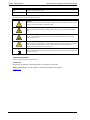
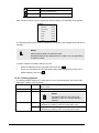
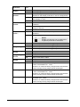
The following icons conventions are used in this document.
Convention
Description
CAUTION!
This icon is used to indicate that there is a danger to equipment. The danger could be loss of data, physical
damage, or permanent corruption of configuration details.
WARNING!
This icon is used to indicate that there is a danger of electric shock. This may lead to death or permanent
injury.
WARNING!
This icon is used to indicate that there is a danger of inhaling dangerous substances. This may lead to
death or permanent injury.
DANGER!
This icon is used to indicate that there is a danger of falling down! There is acute danger, when working with
unsecured ladders. Unsecured ladders can slip and cause a fall that can lead to serious injuries.
Additional information: refer to local „Safety at Work Act“.
NOTE!
This icon is used to highlight useful advice and recommendations as well as information for an efficient and
trouble-free operation.
Tradename statement
ADPRO is a registered trademark of Xtralis AG Pty Ltd.
Contact Us
UK and Europe +44 1442 242 330 D-A-CH +49 4347 903 0 The Americas +1 781 740 2223
Middle East +962 6 588 5622 Asia +86 21 5240 0077 Australia and New Zealand +61 3 9936 7000
www.xtralis.com
ii
Doc. 26571_00
ADPRO Passive-Infrared (PIR) PRO E-Series
Software Manual
Contents
Inhalt
1
Software Installation .................................................................................................................... 1
1.1
1.2
1.3
1.4
Doc. 26571_00
System Requirements ....................................................................................................... 1
Install Software .................................................................................................................. 1
1.2.1 Install on Windows 7/8 Platform .............................................................................. 1
1.2.2 Install on XP Platform .............................................................................................. 4
1.2.3 Configure Communication Port ............................................................................... 7
Use Software ....................................................................................................................11
1.3.1 Select Detector ......................................................................................................12
1.3.2 Select Communication Port ...................................................................................14
1.3.3 File .........................................................................................................................14
1.3.4 Option ....................................................................................................................14
1.3.5 Oscilloscope View (Scope) ....................................................................................26
1.3.6 Diagnostic Functions (Tool) ...................................................................................28
Uninstall Software ............................................................................................................34
ADPRO Passive-Infrared (PIR) PRO E-Series
1
Software Manual
Software Installation
The ADPRO PRO Windows® Software is available as an accessory to the interface module
“IFM-485-ST (formerly IF-485B)”. It is used for commissioning of challenging installations,
optimizing the settings and monitoring the detector/s in use. It can be used for all types of
detectors.
The Software shows all current operation parameters and analog signals of each detector in
real time. This is useful in various situations, such as realignment of the detector, adapting
certain parameters or blanking out objects in the detection area causing unwanted alarms.
NOTE!
The software’s name has been changed from “IF-485B” to “IFM-485ST”; it has the same functionality, but with the following enhancements:
1.1
Destruction of the unit due to over-voltage is avoidable.
Accidental reverse of polarity will not cause damage to the unit.
System Requirements
Before installing the ADPRO PRO Windows® Software, make sure that the following
requirements are available in the computer:
1.2
Microsoft® Windows® PC
Communication Ports: USB or RS232
Install Software
The ADPRO PRO Windows® Software installation wizard allows you to easily install the
Software by providing you with direct and easy-to-follow steps whether installation is made
on an XP or Windows 7/8 platform.
This section discusses how to install the Software on Windows 7/8 and XP platforms, in
addition to configuring the communication port.
1.2.1
Install on Windows 7/8 Platform
To install the Software on a Windows 7/8 platform, do the following:
1.
Unzip the file “Setup_PROXX.zip”,
2.
Rename the file “Setup_PROXX.txt” to “Setup PROXX.exe”,
3.
Double click the file “Setup PROXX.exe”, a Security Warning window appears,
4.
Click (Run), a User Account Control window appears,
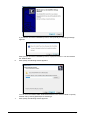
5.
Click (Yes), the ADPRO Setup Wizard installation wizard starts and the following
window appears:
Doc. 26571_00
1
If you want to cancel the installation process, click (Cancel), the following message
appears:
Click (Yes) to cancel the installation process, or (No) to resume it. You can reinstall
the Software later.
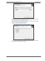
6.
Click (Next), the following window appears:
You can save the ADPRO PRO Windows® Software in the selected folder or specify
another one by clicking (Browse) then selecting it.
7.
2
Click (Next), the following window appears:
Doc. 26571_00
ADPRO Passive-Infrared (PIR) PRO E-Series
Software Manual
The window shows where the Software’s shortcuts will be created, if you want to
specify another folder, click (Browse) and select it.
You can return to the previous window to make the changes you want by clicking
(Back). This button is available in all windows.
8.
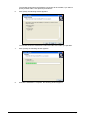
Click (Next), the following window appears:
The window shows the destination location and start menu folder you specified.
9.
Doc. 26571_00
Click (Install), the following window appears:
3
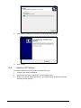
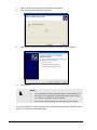
10.
Wait untill the installation is complete, the following window appears:
11.
Click (Finish).
1.2.2
Install on XP Platform
To install the Software on an XP platform, follow these steps:
4
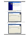
1.
Unzip the file “Setup_PROXX.zip”,
2.
Rename the file “Setup_PROXX.txt” to “Setup PROXX.exe”,
3.
Double click the file “Setup PROXX.exe”, the ADPRO Setup Wizard starts and the
following window appears:
Doc. 26571_00
ADPRO Passive-Infrared (PIR) PRO E-Series
4.
Software Manual
Click (Next), the following window appears:
You can save the ADPRO PRO Windows® Software in the selected folder or specify
another one by clicking (Browse) then selecting it.
5.
Doc. 26571_00
Click (Next), the following window appears:
5
The window shows where the Software’s shortcuts will be created, if you want to
specify another folder, click (Browse) and select it.
6.
Click (Next), the following window appears:
The window shows the destination location and start menu folder you specified.
6
7.
Click (Install), the following window appears:
8.
Wait till the installation is complete, the following window appears:
Doc. 26571_00
ADPRO Passive-Infrared (PIR) PRO E-Series
9.
Software Manual
Click (Finish).
The ADPRO PRO Windows® Software is now installed in your computer in the specified
directory and the following structure is created:
Each sub-folder is responsible for a specification action as follows:
1.2.3
:
Contains all images taken using the Software.
:
Contains all detector configuration files.
:
Contains all statistics and debugger files.
:
Contains all detectors definition files. Each detector model
requires its specific INI file.
:
Contains specific data relevant to the display structure such as
logo on images, etc. This file must not be deleted.
:
Installation program for setup and signal display.
Configure Communication Port
It is important to configure the communication port that will be dedicated to the Software
before you start using it.
Doc. 26571_00
7
If you are using a Windows 7/8 platform, follow these steps to configure the port:
8
1.
Connect the “IFM-485-ST” to the available port,
2.
Right click “My Computer”,
3.
Click “Manage”,
4.
Click “Device Manager”,
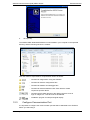
5.
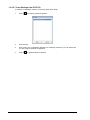
Click “Ports (COM and LPT)”, a list of available ports appears as shown next:
6.
Right click “USB Serial Port (COM3)” to update its driver software,
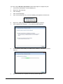
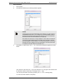
7.
Click (Update Driver Software…), the following window appears:
8.
Select “Search automatically for updated driver software”, the following window
appears:
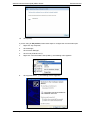
9.
Wait for the search to complete, the following window appears:
Doc. 26571_00
ADPRO Passive-Infrared (PIR) PRO E-Series
10.
Software Manual
Click (Close).
If you are using an XP platform, follow these steps to configure the communication port:
1.
Right click “My Computer”,
2.
Click “Manage”,
3.
Click “Device Manager”,
4.
Click “Ports (COM and LPT)”,
5.
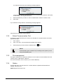
Right click “Communications Port (COM1)”, the following menu appears:
6.
Click (Update Driver…), the following window apppears:
Doc. 26571_00
9
7.
Select “Install the software automatically (Recommended)”,
8.
Click (Next), the following window appears:
9.
Wait while the wizard searches for the update, the following window appears:
10.
Click (Finish).
NOTE!
You can directly connect to the IFM-485-ST via the RS232 com.
Every time you change the communication port you are using,
you need to reconfigure its driver software.
Port number varies depending on the system you are using.
For more information on how to associate the communication port with the Software, refer to
section (1.3.2 Select Communication Port).
10
Doc. 26571_00
ADPRO Passive-Infrared (PIR) PRO E-Series
1.3
Software Manual
Use Software
As mentioned earlier, the Software helps you to optimize the settings and monitor the
detector(s) in use. After you have successfully mounted the detector and configured the
settings you need, you can start using the Software.
Once installed, a shortcut is created for the ADPRO PRO Windows® Software and can be
accessed through the applications menu, it appears as follows:
Activate the Software, the following window appears:
The ADPRO PRO Windows® Software provides various tools and features that allow you to
control and monitor the detectors and maximize their benefit. They are categorized into
menus for easier access.
In addition, you can access any tool or feature through the buttons that appear in the toolbar
as follows:
Image
Action
Open Detector INI
Search Detector
Up/download settings
Debugger
Statistics
Scope
View picture
Run
Stop
Take picture
Moreover, the Software provides shortcuts through the keyboard for faster access to the
required tool, as follows.
Shortcut
Doc. 26571_00
Action
11
<F1>
<F2>
<F3>
<F4>
<Ctrl> + B
<F5>
<Ctrl> + <F5>
<F6>
<F7>
<F8>
<Ctrl> + <F8>
<F9>
<F10>
<Ctrl> + <K>
<Ctrl> + <P>
<Ctrl> + <V>
<Ctrl> + <A>
<Ctrl> + <O>
<Ctrl> + <M>
<Ctrl> + <T>
<Ctrl> + <D>
About the Software
Open detector definition file window.
Search for a detector.
Up/Download
Beep
Run scope
Stop scope
Change scroll direction, “right to left” or “left to right”
Hide/ show grid
Increase signal speed
Decrease signal speed
Clear scope
Delete all triggers
Open scope window
Take picture
View picture
Picture auto
Picture memo
Open statistics window
Test
Open debugger window
The following sections discuss all the actions you can perform, the available tools and how to
use them.
1.3.1
Select Detector
Before you start using the ADPRO PRO Windows® Software, you need to select the
detector to be used. The Software normally finds the detector’s definition file automatically.
This step is only required if there is no automatic loading of the detector.
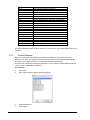
There are two methods for selecting the detector in use in order to load its definition file and
connect it to the “IFM-485-ST” data bus.
First method:
12
1.
Click “File”,
2.
Click (Open Detector INI),the following appears:
3.
Select the detector,
4.
Click (Open).
Doc. 26571_00
ADPRO Passive-Infrared (PIR) PRO E-Series
Software Manual
Second method:
1.
Click “Option”,
2.
Click (Search Detector),the following window appears:
NOTE!
Detectors are given IDs (addresses) in the range of 1 to 254. Factoryset addresses are in the 1 to 10 range. It is recommended to narrow
down the range when searching for a detector so as not to take time
and retrieve the connected detectors more quickly.
Each detector must have a unique address, if more than one detector
is given the same address and connected to the same bus, none of
them will appear on the Software. To resolve this problem, disconnect
all detectors and configure each one separately. This will ensure that
no detector uses the same ID of another one.
3.
Click (Start), or press keys <ALT> + <S>, a list of found detectors appears as shown
below:
The number on the left of the “>” sign is the detector’s ID. The type of the detector and
the firmware version number are on the right of the “>” sign.
You can stop the search process by pressing <ALT> + <S> or clicking (Stop).
To close the search window, click (ESC).
Doc. 26571_00
13
If no detectors are found, the following message appears:
The message shows the possible reasons for not retrieving any detector. Click (OK),
check the error, and repeat the search.
4.
Select the detector you want, or enter its identification number in “Choice” field,
5.
Click (OK).
If you select the wrong detector, the following message appears:
Click (OK) then select the correct detector.
1.3.2
Select Communication Port
To select the communication port to which the “IFM-485-ST” data bus will be connected,
follow these steps:
1.
Click “Option”,
2.
Click “Com Port”, a menu listing the available ports appears,
3.
Select the port you want; it will be marked with a (
) sign.
NOTE!
Communication ports’ numbers vary according to the system you are
using and available ports.
1.3.3
File management
This option enables you to select the detector in use in order to load its definition file and
connect it to the “IFM-485-ST” data bus.
For more information, refer to section (10.3.1 Select Detector).
1.3.4
Option
Through this menu you can search for a certain detector, upload/ download detector
settings, select port, etc.
Option appears as shown next:
14
Doc. 26571_00
ADPRO Passive-Infrared (PIR) PRO E-Series
Software Manual
The following sections discuss, in detail, the actions you can perform.
1.3.4.1
Search Detector
To search for a detector, refer to section (10.3.1 Select Detector).
1.3.4.2
Up/Download
The Software simplifies the process of detector configuration and allows you to save time
spent in setting other detectors values. You can configure a detector and use the same
settings for other detectors of the same type connected to the Software.
You can manage setting options, upload a detector’s settings, download them from a
definition file, and save them to a new definition file, etc.
The Up/Download window appears as follows:
Settings window is detector-model-dependent and is primarily designed to review and
change detector’s parameters. These include the overall sensitivity, mounting height, etc.
The window shows the detailed setting options of the selected detector. It also shows the
actions you can perform where each one is represented with a certain button as follows:
Image
Action
Upload settings to detector
Download detector’s settings
Copy
Doc. 26571_00
15
Insert
Save to configuration file
Load from configuration file
Also, the above actions can be accessed by clicking “Setting”, the following menu appears:
The following sections discuss all the actions you can perform, the available tools and how to
use them.
NOTE!
Setting options depend on detector model.
Displayed positions and displayed terms of option may vary depending
on detector model.
To select a detector to load its settings, you can:
Select the detector from the drop-down menu then click (
Press <F3> and search for it by following the same steps mentioned in section (10.3.1
Select Detector), then click (
).
).
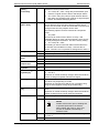
1.3.4.2.1 Setting Options
The Setting window displays the setting options for the selected detector where each field
represents a certain value as follows:
Choice
Lists all detectors of the same model, so that settings can be
easily copied.
Address
Displays selected detector’s identification number.
Configuration
Displays current operation mode: Hardware or Software.
NOTE!
Operation modes can only set by DIPswitches 1 and 2 on connector board of
detector.
Channel L/M/S
16
1)
ON
Long, medium and short range channels may be enabled
individually by selecting “ON” from drop-down menu.
OFF
Long, medium and short range channels may be disabled
individually by selecting “OFF” from drop-down menu.
Doc. 26571_00
ADPRO Passive-Infrared (PIR) PRO E-Series
Software Manual
Output function
[Relay |
Transistor]
If relay function is set to “ON”, the following two options are
available in the drop-down menu:
1. “IR + VAN | IR + VAN”: Using relay and transistor open
collector to signal intrusion alarms and tamper alarms.
2. “IR + VAN”: Using only relay to signal intrusion alarms
and using only transistor open collector to signal tamper
alarms. This allows identifying alarms.
Output
[OC1 | OC2]
This feature is only available with intrinsically safe detectors.
These detectors have two open collector outputs, which
have to be connected via the recommended ex-barriers and
through which two relay outputs can be used.
The following options can be accessed via a drop-down
menu:
1. “IR | VAN”:
This serves to issue intrusion alarms on relay 1 and
vandalism alarms on relay 2 at the ex-barrier, which serves
to clearly distinguish the alarms. This is the factory setting.
2. “IR + VAN | IR + VAN”:
This setting is used to issue both alarms at the same time
for intrusion and vandalism on relays 1 and 2 at the exbarrier. Therefore it is not possible to distinguish the alarms.
Relay function
OFF
Disables output function of relay.
ON
Enables output function of relay.
Relay output
logic
Normal
Relay opens when in alarm.
Inverted
Relay closes when in alarm.
Transistor
output logic
Normal
OC opens when in alarm.
Inverted
OC closes when in alarm.
Channel
3)
right/left
ON/
OFF
Enables/ Disables right/ left channel.
SW sensitivity
1)
right/left [%]
Modifies sensitivity of right/left channel within bandwidth 20
% - 139.39 %.
Reduction of overall sensitivity changes alarm threshold but
leaves coverage of right/left channel unchanged.
SW range
Detection range can be individually set in seven steps. Preset values vary depending on model.
Reduction of nominal range affects only coverage of longrange channel (applies to long-range models only).
SW sensitivity
[%]
Modifies the overall sensitivity within a bandwidth 50% 150%.
Reduction of overall sensitivity changes alarm threshold but
leaves coverage of long-range channel unchanged.
SW ATD
ON
Enables “Adaptive Threshold Discrimination”.
OFF
Disables “Adaptive Threshold Discrimination”.
NOTE!
Disable ATD function prior to walking test
to optimize performance of detector.
When putting “SW Test” to “ON”, ATD
function is disabled automatically in
Software mode.
SW Test
Doc. 26571_00
ON
Enabled to perform walking test with Wireless walking tester
CT PRO 2.
OFF
Disabled for normal operation.
17
SW Vandalism
protection
ON/
OFF
Enables/ Disables “Anti-Tamper Protection”.
SW Mounting
4)
height
HIGH
Mounting height above than 3 m (10 ft).
LOW
Mounting height less than 3 m (10 ft).
Reset vandal
position
ON
Writes new alignment position into non-volatile RAM as
baseline for anti-tamper protection in case of misalignments.
OFF
Upload of settings to control device happens always
automatically in “OFF”.
-
Not selected.
ON
Resets alarm counter to “zero” at next download of settings
to detector.
OFF
No resetting of alarm counter to “zero” at next download of
settings to detector.
-
Not selected.
0 - 10
Number of additional pulses (0 – 10) before an alarm is
generated.
OFF
Disables “Adaptive Threshold Discrimination”.
Reset alarm
counter
SW pulse
2)
count
NOTE!
Disable ATD function prior to walking test
to optimize performance of detector.
Relay Sabotage
OFF
Disables output function of sabotage relay.
ON
Enables output function of sabotage relay.
OFF
Disables output function of Config1 relay.
ON
Enables output function of Config1 relay.
Relay Sabotage
Inverse
OFF
Relay opens when in alarm.
ON
Relay closes when in alarm.
Relay Config 1
Inverse
OFF
Relay opens when in alarm.
ON
Relay closes when in alarm.
Relay Config 2
Inverse
OFF
Relay opens when in alarm.
ON
Relay closes when in alarm.
Relay Config1
18
sensitivity BSS0
Modifies the sensitivity of the Back Sight Survailance Sensor
0 within a bandwidth 50% - 150%.
Reduction of overall sensitivity changes alarm threshold but
leaves coverage of long-range channel unchanged.
sensitivity BSS1
Modifies the sensitivity of the Back Sight Survailance Sensor
1 within a bandwidth 50% - 150%.
Reduction of overall sensitivity changes alarm threshold but
leaves coverage of long-range channel unchanged.
sensitivity IR2
Modifies the sensitivity of the Main Infrared Sensor within a
bandwidth 50% - 150%.
Reduction of overall sensitivity changes alarm threshold but
leaves coverage of long-range channel unchanged.
Doc. 26571_00
ADPRO Passive-Infrared (PIR) PRO E-Series
Delay Relay [ms]
Reset anti
masking
Notes:
Software Manual
Delays the deactivation of the alarm relay in question to up
to 163 seconds (enter in ms from 2 to 163837)
ON
Writes new alignment position into non-volatile RAM as
baseline for anti-tamper protection in case of masking the
front of the detector.
OFF
Upload of settings to control device happens always
automatically in “OFF”.
-
Not selected.
1
2
3
4
Applies only to long-range detector models
Applies only to directional detector models
Applies only to volume detector models
Applies only to PRO-51/ -85/ -85H/ -100/ -100H und -250H
The following Setting window shows the dynamic changing of setting possibilities depending
on model; e.g. of a multi-zone detector PRO-250H
Also, the Setting window provides you with additional information regarding the setting
options, as shown in the following figure:
The above example shows help information regarding the detector’s address.
To view the help information of any other field, simply place the cursor in the required field
and the information appears in the upper box.
Doc. 26571_00
19
To close the Setting window, click (
).
NOTE!If you attempt to close the Settings window before saving the
changes you make, the following message appears:
If you are sure you want to exit the window without saving, click (Yes);
otherwise, click (No) then save the changes you made.
1.3.4.2.2 Upload Settings
To upload settings to detector, follow these steps:
1.
Make the changes you want to the fields you can change,
2.
Click (
). Successful upload is represented with (
).
NOTE!
Make sure to click (
they are lost.
) to save the changes you made; otherwise,
1.3.4.2.3 Factory Settings
You can reinstate the factory default configuration to the detector instead of the changes you
made in the following cases:
The detector does not seem to work properly.
A previous version of the ADPRO PRO Windows® Software was used on the same
detector.
To display and use the factory default settings, follow these steps:
1.
Click (Factory), the following message appears:
2.
Click (Yes) to replace the values with the factory ones,
3.
Click (
) to save them in the detector’s configuration file.
1.3.4.2.4 Download Settings
To download the detector’s settings, follow these steps:
20
1.
Make the changes you want,
2.
Select the detector,
3.
Click (
).
Doc. 26571_00
ADPRO Passive-Infrared (PIR) PRO E-Series
Software Manual
The configuration status is represented with the following symbols:
:
Uploading configuration
:
Changed configuration
:
Communication problem
:
Downloading configuration
1.3.4.2.5 Copy Settings
To copy the settings of a detector and use them in another one, follow these steps:
1.
Select the detector which settings you want to copy,
2.
Click (
3.
Select the detector to which you want to apply the copied settings,
4.
Click (
),
).
1.3.4.2.6 Save Settings to CFG File
To save the configuration in the “CFG” sub-folder accessed through the ADPRO PRO
Windows® Software folder saved in the computer, follow these steps:
1.
Make the changes you want,
2.
Click (
3.
Enter file name,
4.
Click (OK) to save, or (Abort) to cancel the action.
Doc. 26571_00
), the following field appears:
21
1.3.4.2.7 Load Settings from CFG File
To load the configuration saved in a CFG file, follow these steps:
22
1.
Click (
), the following window appears:
2.
Select the file,
3.
Click (Open), the configuration appears in the Settings window so you can make sure
you are using the desired configuration.
4.
Click (
) to upload settings to detector.
Doc. 26571_00
ADPRO Passive-Infrared (PIR) PRO E-Series
1.3.4.3
Software Manual
Output settings
The detector allows to freely assign different output events to all available output relays
Enter the output setting mode via top menu “Settings” -> “Output Settings”
The “ouput setting window” allows to match up to 5 output relays (depending on detector model) with
any kind of event or alarm the detector can create. (depending on detector model) with any kind of
event or alarm the detector can create:
Depending on the amount of available alarm inputs and the ability to distinguish between the differnet
events, you can freely assign events to outputs.
Example one, using three relays, as pictured above:
1. Intrusion: Relay triggers, in case the IR sensor detects movement in the main zone
2. Tamper: Relay triggers, in case the bracket cover switch is opened or the main housing is
opened or the alligment is changed.
3. Fault: Relay triggers if a technical error occurs, like power failure or if the outside temperature
is out of range of the specified operational range.
Note: Output 4 and 5 are not used, also the creep zone alarm, anti masking and pulse count
event are not reported through any output and would go unnoted.
Doc. 26571_00
23
Example two, using all five relays:
1. Intrusion: Relay triggers, in case the IR sensor detects movement in the main zone
2. Tamper: Relay triggers, in case the bracket cover switch is opened, the main housing is
opened or the alligment is changed.
3. Fault: Relay triggers if a technical error occurs, like power failure or if the outside temperature
is out of range of the specified operational range.
4. Config1: Relay triggers, if there is an anti masking alarm
5. Config2: Relay triggers, if there is a creep zone alarm
Note: all alarms and events are reported and can be distinguished in all details.
1.3.4.3.1 Events leading to a “main” alarm:
alarm (IR)
alarm_medium range (IR), alarm_long range (IR), alarm_short range (IR)
alarm creep zone (CH1+CH2)
masking detection (together with intrusion FAULT)
Power on
*)
*) multi-channel detectors only
1.3.4.3.2 Events leading to a “fault” alarm:
power failure
masking detection (together with intrusion ALARM)
heat system error (when heater installed)
flash problems
operational temperature out of range
self-test compass failed
self-test G-sensor failed
wrong model selected; refer to Fig. XX (Rotary Switch Mapping)
power on
1.3.4.3.3 settings: (Alles identlisch mit den “Standard” Settings)
24
Doc. 26571_00
ADPRO Passive-Infrared (PIR) PRO E-Series
Software Manual
The window shows the detailed setting options of the selected detector. It also shows the
actions you can perform where each one is represented with a certain button as follows:
Image
Action
Upload settings to detector
Download detector’s settings
Copy
Insert
Save to configuration file
Load from configuration file
Also, the above actions can be accessed by clicking “Setting”, the following menu appears:
The following sections discuss all the actions you can perform, the available tools and how to
use them.
NOTE!
Setting options depend on detector model.
Displayed positions and displayed terms of option may vary depending
on detector model.
To select a detector to load its settings, you can:
Select the detector from the drop-down menu then click (
Press <F3> and search for it by following the same steps mentioned in section (10.3.1
Select Detector), then click (
1.3.4.4
).
).
Communication Interface (Com Port)
For more information on how to select the port you want to use, refer to section (10.3.2
Select Communication Port).
1.3.4.5
Language Selection
The Software provides the settings and parameters in various languages displayed in this
menu.
To switch between the available languages, follow these steps:
Doc. 26571_00
25
1.
Click “Language”,
2.
Select the language you want.
Parameters and settings are now displayed in the selected language, but as for the interface
language itself it is only available in English.
1.3.4.6
Beep
If this option is checked, whenever the detector detects something, you’ll hear a beep.
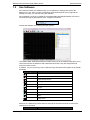
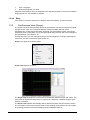
1.3.5
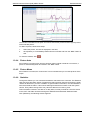
Oscilloscope View (Scope)
The Scope view is the most powerful feature of the software. It shows in real-time the signal
strength of each zone, if the monitored detector features multiple detection zones.
Simultaneously, it shows the actual alarm threshold, the general alarm status, and various
parameters such as total alarm count, strongest signal level received, and current settings of
the DIP switches in the detector, etc.
Through this menu you can manage the Scope view by stopping or running it, selecting the
view mode, increase or decrease signal speed, etc.
Scope menu appears as shown below:
Scope view appears as follows:
The Scope view illustrates the cause/response relationship between inputs and output. The
view shows all signals and their levels on a time axis; it allows for a detailed analysis of the
detector’s operation.
The Scope view appears automatically after a detector has been selected from the search
list. The signals on the screen represent the current readings of the detector and are helpful
for resolving problems as well as managing certain installation features.
26
Doc. 26571_00
ADPRO Passive-Infrared (PIR) PRO E-Series
Software Manual
The Scope window is divided into the following three parts:
Scope view (black, left): Scope view is used to for signal monitoring; it shows IR
amplitude, alarm-threshold and other vital parameters in real-time. In addition, it shows a
varying amount of lines as follows:
Green (Sensor Signal): shows the signal levels of the PIR sensor.
Red (IR Alarm): shows the IR event caused by the sensor signal.
Purple (output alarms): shows the actual output signal at relay, depending on
model and setup up to 5 signals, General, Sabotage, Fault, Config1 and Config 2.
Blue (Alarm threshold).
Yellow (Vandalism Alarm). Shows the detector has been misaligned.
NOTE!
Alarms appear on Scope view only if the alarm generating detector is
selected.
Table of Settings (top-right): This table shows the current settings of the selected
detector; it consists of the detector’s parameters such as sensitivity, desired detection
range, their values and unit.
To view the values of a certain parameter, click it, its values appear as shown below:
The selected parameter’s values appear in view-mode only. Any changes made to the
settings are directly reflected on this table and the threshold.
NOTE!
Information displayed in table may vary depending on detector model.
Doc. 26571_00
27
You can control the Scope view through the following:
Action
Run the Scope
Stop the Scope
Select Scope view mode
Increase signal speed
Decrease signal speed
Clear Scope view
Delete all triggers
Button
Run
Stop
Scroll Mode
Grid
Step up++
Step down- Clear
Trigger Delete ALL
Shortcut
<F5>
<Ctrl> + <F5>
<F6>
<F7>
<F8>
<Ctrl> + <F8>
<F9>
<F10>
As shown in the table above, there are two scope modes:
1.3.6
Scroll Mode: If checked, the signal is continuous and its direction is from right to left. If
unchecked, the signal’s direction is from left to right and each time <F6> key is pressed
the signal starts from the beginning.
To switch between Scroll modes press <F6>.
Grid: If selected, horizontal and vertical lines appear on the Scope in addition to the
signals.
Diagnostic Functions (Tool)
This menu enables you to take pictures of the scope and save them in the computer, view
statistics of alarm states, and identify communication problems, etc.
Tool menu appears as follows:
The following sections discuss all the actions you can perform.
1.3.6.1
Scope View
To open the Scope view, click (Scope) or press <Ctrl> + <K>.
For more information on actions you can perform in Scope view, refer to section (10.3.5
Scope).
28
Doc. 26571_00
ADPRO Passive-Infrared (PIR) PRO E-Series
1.3.6.2
Software Manual
Picture Take
This tool enables you to take pictures of the Scope view and save them in the “BMP” subfolder accessed through the ADPRO PRO Windows® Software folder. You can use them to
compare readings, monitor readings on certain times, etc.
To take a picture and save it, follow these steps:
1.
Click (Picture take), the following field appears:
2.
Enter your comment,
3.
Click (OK).
The picture is saved in the BMP and given a name according to the following naming
convention:
“PRO-Model No-yymmdd_nnn.txt” where: yy=year, mm=month, dd= day, nnn=sequential
number (1 - 999).
To view a picture, open it from the computer, it appears as follows:
Doc. 26571_00
29
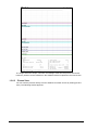
The image shows the Scope, comment, and settings at the time that picture was saved.
However, pictures can be viewed from the Software itself as explained in the next section.
1.3.6.3
Picture View
You can view the pictures directly from the Software for easier access by clicking (Picture
view). The following window appears:
30
Doc. 26571_00
ADPRO Passive-Infrared (PIR) PRO E-Series
Software Manual
The window is divided into two parts: the left one lists all the pictures and the right a preview
of the selected picture.
To delete a picture, follow these steps:
1.
Select the picture, its name is displayed in the field,
2.
Click (Delete). It is immediately deleted from this window and from the “BMP” folder as
well.
To close the window, click (
1.3.6.4
).
Picture Auto
If this feature is checked, each time the detector reads a signal or detects a movement, a
picture is automatically taken and saved in the “BMP” folder.
1.3.6.5
Picture Memo
If this feature is checked, the “Picture take” tool is activated and you can take pictures of the
Scope.
1.3.6.6
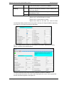
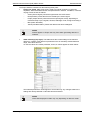
Statistics
Through this feature you can view data the detector transmits to the controller. The Statistics
view logs the actual alarm status of all detectors that have been discovered during the initial
“Search for Detectors” process. In addition to general alarm information, the view details the
zone that issued the alarm. It also shows warnings and detector‘s status under the system
column. Every status change from every detector adds a line in this log view.
This information is stored in text files on a daily basis, one file per detector. Files are saved
in the “DAT” sub-folder accessed through the ADPRO PRO Windows® Software folder.
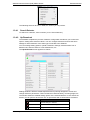
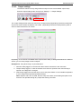
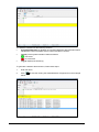
Click (Statistics), the following window appears:
Doc. 26571_00
31
The window is divided into the following sections:
Connected Detectors (1): displays all connected detectors with information about
identification number, firmware version number and alarm counters.
Type (2): Each symbol indicates a status as follows:
(
): connected.
(
): not connected.
Log (3): displays the actual log.
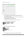
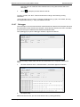
To generate a statistics file and save it, follow these steps:
32
1.
Enter file name,
2.
Click (
below:
) to start the viewing the transmitted data, it appears as in the example
Doc. 26571_00
ADPRO Passive-Infrared (PIR) PRO E-Series
Software Manual
Note that a line is created for each detected event, along with the date and event
description.
3.
Click (
) to stop the process and save the file.
The file is saved in the “DAT” folder and named according to the following naming
convention:
“STAz-yymmdd_nnn.xxx” where: z=number of statistics file, yy=year, mm=month, dd= day,
nnn=sequential number (1 - 999), xxx=address number.
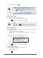
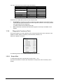
1.3.6.7
Debugger
This tool helps record all communication made between the detector and computer and save
this information in files stored in the computer. These files are saved in the “DAT” sub-folder
accessed through the ADPRO PRO Windows® Software folder.
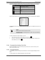
Click (Debugger) to open the Debugger window, it appears as follows:
To start recording of data traffic and save this information in the computer, follow these
steps:
1.
Click the checkbox next to “Communication”, the window appears as follows:
2.
Click (New File).
Data is saved in the file; you can create another file by clicking (NewFile).
Doc. 26571_00
33
To stop recording of data, click (Clear).
Files are named according to the following naming convention:
“DBG-yymmdd_nnn.txt” where: yy=year, mm=month, dd= day, nnn=sequential number (1 999).
The following abbreviations are used in data recording:
Abbreviation
ErrA
ErrK
ErrW
ErrP
ChkSum
Tmo
Buf
1.4
Error
Error counter
Error counter configuration
Error counter working
Error counter synchronisation
Error counter check sum
Error counter timeout
Error counter buffer
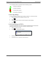
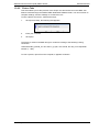
Uninstall Software
You might need to uninstall the ADPRO PRO Windows® Software for any reason; the
Software enables you to do so by providing you with a user-friendly wizard.
To uninstall the Software, follow these steps:
34
1.
Open the folder in which you have installed the Software,
2.
Double click on “unist000.exe”, the following message appears:
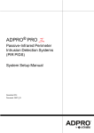
3.
Click (Yes), the following window appears:
4.
Wait till the uninstallation process is complete, the following message appears:
Doc. 26571_00
ADPRO Passive-Infrared (PIR) PRO E-Series
5.
Doc. 26571_00
Software Manual
Click (OK).
35
ADPRO Passive-Infrared (PIR) PRO E-Series
Software Manual
www.xtralis.com
UK and Europe +44 1442 242 330 D-A-CH +49 4347 903 0 The Americas +1 781 740 2223
Middle East +962 6 588 5622 Asia +86 21 5240 0077 Australia and New Zealand +61 3 9936 7000
The contents of this document are provided on an “as is” basis. No representation or warranty (either express or implied) is
made as to the completeness, accuracy or reliability of the contents of this document. The manufacturer reserves the right to
change designs or specifications without obligation and without further notice. Except as otherwise provided, all warranties,
express or implied, including without limitation any implied warranties of merchantability and fitness for a particular purpose are
expressly excluded.
This document includes registered and unregistered trademarks. All trademarks displayed are the trademarks of their
respective owners. Your use of this document does not constitute or create a licence or any other right to use the name and/or
trademark and/or label.
This document is subject to copyright owned by Xtralis AG (“Xtralis”). You agree not to copy, communicate to the public, adapt,
distribute, transfer, sell, modify or publish any contents of this document without the express prior written consent of Xtralis.
Doc. 26571_00
P/Nxxxxxx