1
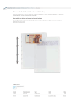
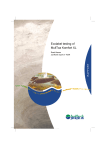
Currency counters
English
User manual
PRO 95 / PRO 95U
www.pro-intell.com
PRO 95 SERIES
PRO Intellect Technology offers the PRO 95 series of banknote counters as reliable, fast and
accurate devices for counting and authenticating medium to large volumes of banknotes from
a variety of currencies, including USD, EURO, and others. The high counting speed provides
quick and accurate processing of banknotes as well as 3 types of counterfeit detection that
work simultaneously to authenticate banknotes: width, optical density, and UV reflection.
These devices are ideal for use in banks, exchanges, payroll offices, supermarkets, and other
retail outlets. The remote display allows the device to be seamlessly integrated into the
workplace with maximum convenience for the operator.
This manual will help you to easily and quickly get acquainted with the device, its functions,
and its capabilities. Please read this manual to ensure proper operation of the device.
1
•
•
•
•
Main functions of PRO 95 series counters
Banknote counting; adding new figures to previously counted banknote, package mode.
Recognition of suspicious banknotes with UV detector
Optical density and double banknote detection.
Banknote width detection.
Distinctive features
• 2 counting speed: 900/1200 banknotes per minute
• Hopper capacity/stacker capacity: 600/300 banknotes
• UV detection: 4 levels
• Detection of optical density: 8 levels
• Banknote width detection: 6 levels
• Preset batch mode: buttons 0-9
• Summation mode
• Manual and automatic start
• Auxiliary hopper plates
• Audio confirmation of operation mode
• External display option
2
2
Appearance
Figure 1
3
Appearance
1. Control panel
2. Hopper
3. Stacker
4. Auxiliary hopper plates
5. Paper thickness adjustment strew
6. Carrying handle
7. Power switch
8. Power cord
9. Cover
10. External display Port RS-232
3
•
•
•
•
•
•
•
•
•
•
Specification
Counting speed . . . . . . . . . . . . . . . . . . . . . . . . . . . . . . . . . . . . . . . . 1200/900 banknote/min
Feed capacity. . . . . . . . . . . . . . . . . . . . . . . . . . . . . . . . . . . . . . . . . . . . . . . . . 600 banknotes
Hopper . . . . . . . . . . . . . . . . . . . . . . . . . . . . . . . . . . . . . . . . . . . . . . . . . . . . . . 300 banknotes
Counting mechanism capacity . . . . . . . . . . . . . . . . . . . . . . . . . . . . . . . . . . . . . . . . . . 0-9999
Range of spacified counting. . . . . . . . . . . . . . . . . . . . . . . . . . . . . . . . . . . . . . . . . . . . . 1-999
Power consumption. . . . . . . . . . . . . . . . . . . . . . . . . . . . . . . . . . . . . . . . . . . . . . . . . . . . 50 W
Power . . . . . . . . . . . . . . . . . . . . . . . . . . . . . . . . . . . . . 220V/50Hz (For U.S. - 110V/60Hz)
Net weight . . . . . . . . . . . . . . . . . . . . . . . . . . . . . . . . . . . . . . . . . . . . . . . . . . . . 6.3kg (13.9lb)
Gross weight . . . . . . . . . . . . . . . . . . . . . . . . . . . . . . . . . . . . . . . . . . . . . . . . . . 7.0kg (15.4lb)
Overall dimensions . . . . . . . . . . . . . . . 270х240х240mm (10 3/5”(L) x 9 2/5”(W) x 9 2/5”(H))
4
Control panel operation
1. Batch display
Depicts:
• a number of chosen banknotes in batch mode
• error messages
• changes in parameter on the display 2
2.Main count display
Shows counting results and information concerning:
• Level of UV sensor sensitivity
• Optical density level
• Banknote width sensitivity level
3. “ADD” button
ON/OFF summation mode, (indicator lights up when ON)
4. “MUL” button
This button chooses manual or automatic counting mode.
Press “START/STOP” button to start counting in the manual mode.
In automatic mode the counter starts automatically when you place a stack of banknotes in
the hopper, (indicator is off by default).
5. “SP” button
This button changes the counting speed. When the indicator is on, the device will process
4
Figure 2
5
1,200 banknotes per minute. When the indicator is off, the device will process 900 banknotes
per minute.
6. “UV” button
Switch ON/OFF UV detection (indicator lights up if ON)
7. Indicator of functions in use.
When the indicator is lit up, that function is activated
8. Digit buttons
Used for entering number values on display 1 in batch mode (counting of a specified number
of banknotes).
Press any button (0-9) to enter batch mode automatically.
9. “CLR” button
Reset display 1. Press this button to exit batch mode.
10. “SET” button
Press the “SET” button to check the counter’s settings. This button also allows the operator
to change the device’s settings. (see Table7).
11. “START/STOP” button
Press this button to do the following:
• start counting
• stop counting
• zeros counting results on the main display 2
• resets the error messages on the display 1
• stores changes in settings
5
Safety precautions
• It is important to read the entire contents of this manual prior to operating the device, in order
to ensure proper functionality and safety.
• The manual should be available to operator
• The device should be installed on an even horizontal surface, away from water and dangerous objects.
• Do not use this device under the following conditions:
-The device is not resting on a level surface
-The device will be exposed to vibration while in use
-The device is in an excessively dusty or polluted room
-The device is exposed to direct sunlight or strong directional interior lighting
-The device is near other dangerous objects
• Do not operate the device with wet hands
• Do not expose to water (or other liquid). Avoid foreign objects
• Avoid dropping the device
• During operation: When finished be sure there are no banknotes in the hopper or transport
system
• Clean the device regularly and service the device as needed at a licensed service center to
ensure the device will function within its specified parameters
• Do not disassemble, repair or attempt to update the counter on your own. This can result in
damage to the device or injury to the operator
• If the device was exposed to cold for an extensive period of time, it is necessary to keep it
at the room temperature for no less than 4 hours, when the device has not been stored in a
box. If the device has been stored in a box while expose to cold temperature, allow the device
6
to sit at room temperature for 12 hours prior to use.
Remember! The producer is in no way responsible for damage to the device or injury to the
operator in the event of incorrect operation /care of the device.
6
Counter operation
Preparation
• Connect the power cord to the device
• Turn power switch ON
• Counter starts
• “0” is shown on the main display 2
• If an error message occurs (on display 2), see Table 8
6.1. Counterfeit detection
The PRO 95U model incorporates UV detection. Press the “UV” button to switch UV detection ON/OFF (indicator lights up if ON). When a banknote with suspicious UV reflection properties is scanned, the counter stops and will display an error message “CF-1”. The suspicious
banknote will remain on the top of the stack.
6.2. Counting procedure
ATTENTION! In order to avoid errors during counting, examine banknotes and put aside the
following:
• any banknote that has been repaired with white paper, tape, or another foreign substance
• any banknote that has been exposed to water or “washed”
• any banknote that is excessively dirty or worn
• any banknote that is torn
Banknote should be placed in a neat stack before being placed into the hopper!
• Banknotes are to be placed in the hopper
• The counter will start counting automatically after a second
• The display 2 will show the counting results
• Repeat again up to Table 6.2., when necessary
• Press “START/STOP” button to reset display 2 when finished
• If an error occurs during counting, see Table 8
6.3. Batch mode
(Counting mode for a specified number of banknotes)
• Enter a number corresponding to the amount of banknotes for the desired batch size on the
display (Fig.2-1) by pressing the digit buttons (Fig. 2-8)
• Repeat from the beginning of Table 6.2., when necessary.
• Remove banknotes from the stacker
• Add banknotes if necessary
• Press “CLR” button to reset the display and exit batch mode
• If an error occurs during counting, see Table 8
• Repeat from the beginning of Table 6.2.
6.4. Summation mode
• Press “ADD” button and the LED indicator will light up
• Repeat operations up to Table 6.2.
• When there are no more banknotes in the hopper, remove banknotes from the stacker
• Put a new stack of banknotes into the hopper
• Repeat from the beginning, when necessary
• The display 2 will show the total result of counted banknotes
7
• Press “START/STOP” button to clean the result when finished
• If an error occurs during counting, see Table 8
• Repeat operations up to Table 6.4., when necessary
7
Function settings
ATTENTION! Follow these guidelines carefully to avoid errors during operation.
7.1. Adjustment of the slot size
Remember! Adjusting the feeder slot size is possible by using the paper thickness adjustment
screw (Fig. 1-5) on the rear panel. Turn the screw counterclockwise to decrease the feeder
slot size and clockwise to increase the size. The feeder slot should be larger for excessively
worn banknotes, dirty banknotes and USD. The feeder slot should be smaller for “new” banknotes. Adjust turning should be done smoothly, with a pitch of 5 degrees or less. Counter
speed should be 1200 banknotes per minute.
If adjusting the feeder slot size results in the sensor responding slowly, slow separation of
joined banknotes, irregular stacking of banknotes, and/or error “HAF” occurs, then the slot
size should be smoothly increased without exceeding a rotation of more than 5 degrees.
If adjusting the feeder slot size results in “dbL”, “dd”, or “CHn” error codes occuring frequently, then the slot size should be smoothly decreased without exceeding a rotation of more than
5 degrees.
7.2. Change settings
To enter the mode for changing the device’s settings, press the digit button “5” three times on
the control panel.
7.2.1. Changing the sensitivity level for UV detection
Press “SET” button until the “CF-1” sign shows on the display. Enter a number from 0 to 3,
which corresponds a sensitivity level from low to high. “0” corresponds to UV detection being
turned OFF.
Press “START/STOP”. Recommended level: CF-1=2.
7.2.2. Changing the acceptable width range for banknotes
Press “SET” button until “dd” sign shows on the display. Enter a number from 3 to 7, which
corresponds to a width sensitivity level from 3 to 7mm. “0” corresponds to size detection being
turned OFF. Press “START/STOP” button. Recommended level: dd=4
7.2.3. Change the sensitivity of optical density
Press “SET” button until “dBL” sign appears. Enter the level of optical density (0-7). Larger
values correspond to more dense notes. Smaller values correspond to less dense or older /
worn notes. Press “START/STOP” button. Recommended level: dBL=4
Attention! New settings are stored for future use.
Remember! Wrong settings can cause failures and frequent error messages. Error
messages listed in Table 8.
8
8
Error codes
Technical maintenance
In order to provide the best functioning of the device, it is necessary to comply with the
following simple requirements:
Switch off the device, when not in use
Use protective cover, when not in use
Clean the hopper and stacker with a clean dry cloth. Sensors can cause errors when
dirty.
It is recommended to carry out preventive measures, including partial disassembling of
the counter each 30 days by an engineer in the service center.
Error
code
HAF
CHn
DbL
Reason
1.Halved banknote detected
2. Left or right sensor failure
Chained note detected
Double banknote detected
dd
1. Banknote with different width
detected.
2. Wrong banknote position.
CF1
Suspicious note detected by UV
Solution
1. Remove the banknotes from the stacker, take
away the suspicious banknote (lying on the top),
and repeat the counting procedure
2. Contact the service center
1. Remove the banknotes from the stacker, and
repeat the counting procedure
2. Adjust the slot (Table 7.1.)
1. Remove the banknotes from the stacker, take
away the suspicious banknote (lying on the top)
and repeat the counting procedure
2. Adjust the slot, see Table 7.1.
3. Set lower sensitivity level, (see Table 7.2.3.)
1. Remove the banknotes from the stacker, take
away the suspicious banknote (lying on the top),
and repeat the counting procedure
2. Set the sensitivity level lower, (see Table
7.2.2.)
Remove the banknotes from the stacker, take
away the suspicious banknote (lying on the top),
and repeat the counting procedure
9
System errors
Code
Reason
Solution
E01, E03
left sensor is either blocked or
Clean or replace the sensor
failed
E02, E04
right sensor is either blocked or
Clean or replace the sensor
failed
E05
Feed hopper sensor is either Remove banknotes from the
blocked or failed
stacker, clean or replace the sensor
E06
Start sensor is either blocked or Remove banknotes from the
failed.
stacker, clean or replace the sensor
E07
Speed sensor is either dirty or
clean or replace the sensor
failed
In case of system errors E01-E07 contact service centre.
10
9
Warranty
Manufacturer guarantees proper functioning of the device during the warranty period
since the date of sale under condition of compliance with maintenance and storage
procedures described in this manual. After unpacking the device please keep the
package and technical description. Warranties are canceled in the event that the device
was not transported in the original packaging or maintenance procedures were violated.
Manufacturer is not responsible for device malfunction as a result of improper
maintenance, storage and transportation including mechanical failures.
In case of the device failure during the warranty period, the customer has the right to
have it repaired in our service center for free. The service center accepts equipment for
cleaning due to dust and mud, however cleaning equipment from dust and mud is not
included in the warranty and is charged separately.
Warranty service does not include any training for equipment maintenance or other use
of the device (connection, testing, customizing, preventive works etc.) which the
customer can complete on their own by referencing the attached manual.
Producer is entitled to introduce updated software, not described in the current manual.
Warranty service is not available in the following cases:
- Absence of a warranty card, an incorrectly filed warranty card, or other invalid card
- If operation or maintenance rules mentioned in the manual were violated
- If there is mechanical damage to the equipment
- If there are foreign objects or liquid inside of the device
The present warranty does not apply to lamps, batteries, belts, network adaptors, power
units, safety fuses, brushes, parts of the body of the product or any other parts which
have a naturally limited period of service including failures caused by power supply
failures. Replaced defective parts are to be considered the property of the producer. The
owner delivers faulty equipment to the service center at their own expense.
11
© PRO INTELLECT TECHNOLOGY / www.pro-intell.com