1
Prototype Parking Meter System – Phase 3
Status Report
Team Code
:
May05-02
Client
:
Doug Houghton
Captain
Department of Public Safety
Iowa State University
Advisors
:
Prof. John Lamont, EE/CprE
Prof. Ralph Patterson III,
EE/CprE
Team Members
:
Chris Dasch, CprE
Jesse Pink, EE
Peter Stoltenow, CprE
Kwan Sin Wing Ted, CprE
Andrew Ross, EE
REPORT DISCLAIMER NOTICE
DISCLAIMER: This document was developed as a part of the requirements of an electrical and computer
engineering course at Iowa State University, Ames, Iowa. This document does not constitute a
professional engineering design or a professional land surveying document. Although the information is
intended to be accurate, the associated students, faculty, and Iowa State University make no claims,
promises, or guarantees about the accuracy, completeness, quality, or adequacy of the information. The
user of this document shall ensure that any such use does not violate any laws with regard to
professional licensing and certification requirements. This use includes any work resulting from this
student-prepared document that is required to be under the responsible charge of a licensed engineer or
surveyor. This document is copyrighted by the students who produced this document and the associated
faculty advisors. No part may be reproduced without the written permission of the senior design course
coordinator.
Submission Date :
1 April 2005
Table of Contents
List of Figures
List of Tables
List of symbols and definitions
1. Executive Summary
2. Acknowledgement
3. Problem Statement
3.1 General Problem Statement
3.2 General Solution Approach
4. Operating Environment
5. Intended Users
6. Intended Uses
7. Assumptions
8. Limitations
9. Expected End Result and Other Deliverables
10. Previous Accomplishments
11. Present Accomplishments
12. Required Future Activities
13. Current Project and End-Product Status
14. Recommendation for Continued Effort
15. Documentation of Current Efforts and Results
16. Implementation Activities
17. Testing and Modification Activities
18. Estimated Resources and Schedule
19. Lessons Learned
20. Risk and Risk Management
21. Project team information
22. Closing Summary
23. References
ii
iii
iv
1
2
2
2
3
4
4
4
5
5
5
6
7
7
8
9
9
10
21
24
29
30
31
32
32
Appendix A – Parking Enforcement Officer Evaluation Form
Appendix B – Patron Evaluation Form
33
34
i
List of Figures
Figure
Figure
Figure
Figure
Figure
Figure
Figure
Figure
Figure
Figure
Figure
Figure
Figure
1 – ATM-like interface
2 – Hypothetical Parking System Implementation
3 – Parking Lot Sign
4 – System Block Diagram
5 – Server unit hardware block diagram
6 – Client Hardware Block Diagram
7 – Client Software Block Diagram
8 – parkingMeter.exe screenshot
9 – Screenshot of user interface
10 – Example of test cases
11 – Example of bug log
12 – Gantt Chart, Project deliverables
13 – Gantt Chart, Project tasks and subtasks
1
3
5
10
11
15
18
19
21
22
23
27
28
ii
List of Tables
Table
Table
Table
Table
Table
Table
Table
1
2
3
4
5
6
7
–
–
–
–
–
–
–
Server unit hardware specifications and costs
Database Structure
Rate Categories
Server unit hardware specifications and costs
Personnel Effort Requirements (revised)
Other Resource Requirements
Financial Requirements
12
13
14
15
25
25
26
iii
List of symbols and definitions
A
B
C
C++
A high-level object-oriented programming language—the language used for the
software in this project
Client
Metal kiosk which contains the user-interface (LCD display, printer, coin accepter
and keypad) and provides administrative capabilities. All users interact with the
client unit to pay for parking or to change settings in the parking system.
D
Dec04-02
The senior design group responsible for the second phase of the project
DPS
Department of Public Safety, the division of Iowa State University responsible for
monitoring parking on the campus
E–F–G–H–J–K
L
LCD
Liquid crystal display, a low-power digital display that uses liquid crystal cells that
change reflectivity in an applied electronic field
Linux
An open source operating system based on UNIX traditionally used for servers.
M
May04-02
The senior design group responsible for the first phase of the project
Motherboard
For this project, it is a main circuit board of the embedded computer through
which all signals are directed.
MySQL
MySQL is a fast-relational database manager. A database manager enables
adding, retrieving, and processing information stored in a database. The
relational aspect of MySQL means that data is stored in separate tables rather
than one large table. Relations between each table can be established and
information can be retrieved using structured query language (SQL).
iv
N–O–P–Q
R
RAM
Random-access memory, the primary working memory in a computer used for
the temporary storage of programs and data and in which the data can be
accessed directly and modified
S
SQL
A standardized language that approximates the structure of natural English for
obtaining information from databases
Server
One machine that contains the mySQL database for a given parking lot
Server Unit
A pair of servers with replicated databases and failsafe capabilities
T
U
USB
Universal serial bus, a plug-and-play interface between a computer and
peripheral devices, such as printers, modems, and keyboards
V
W
Window XP Embedded
A compact and modular operating system provided by Microsoft Corporation that
allows users to select the exact features and functionality of the OS required for
the application or device—the operating system used for the client unit in this
project
Wired Ethernet
A trademark for a system for exchanging messages between computers on a
local area network using wired coaxial, fiber optic or twisted-pair cables
X–Y–Z
v
1. Executive Summary
There are a number of reasons that a new
parking meter system is needed. Currently,
the university is planning the need for new
public parking lots and the current parking
meter systems are too expensive to maintain,
not configurable enough, and don’t allow for
communications between individual units
within the same lot. This project will address
all three of these issues by implementing a
complete system with a simple, ATM-like user
interface.
Figure 1 – ATM-like interface
Currently, the system is relatively inexpensive
to manufacture, coming in at around $1,500. If you include man-hours, the system will
cost only $15,000. The top of the line systems on the market out there weigh in at
over $75,000 and do not have all the planned features that this project will implement.
Even with a commercial market mark-up of 400%, the system will still be less expensive
than other products.
Configuration considerations were also a major reason for beginning this project.
Systems that are currently available on the market today do not have the necessary
options to facilitate all the different dates (holidays, breaks, etc.) and rate schedules
that have been implemented with this project. Additionally, the design of this parking
meter system is expandable and another project team can add features in the future.
Finally, the need for individual units (henceforth referred to as clients or client units) to
communicate, even though they may be at opposite ends of a parking lot or on
different levels of a parking ramp was very important in the design considerations of
this parking meter system. The system allows for customers to add time to the stall
where their car is parked from any client unit in that lot, regardless of which client unit
was originally used to pay. This communication also aids parking supervisors and
administrators with managing the lot by allowing them to print off the unpaid stall list
from any client unit instead of printing off a list from each unit (as it is with the current
system.)
The system will accomplish many of the aforementioned features by implementing a
client-server parking scheme. Throughout a parking lot, a number of client units will
allow customers, administrators, and supervisors to perform various tasks, such as
paying for and adding time to a stall (for customers), updating rate schedules, adjusting
how many stalls are available in a particular lot, checking for parking violations (for
supervisors/administrators) in addition to many other features. These clients will
communicate with a centralized server unit that can either be located in a physically
different location as the client units (such as in a building) or in an enclosure with one
1
of the client units (along with the LCD, coin accepter, printer, etc.) This server will
store all the relevant data for a particular parking lot—all of the stall information (paid,
unpaid, expirations, etc.), the rate structure, and all statistics for that lot.
As of this writing, the hardware has been completely integrated into the case and the
software is also complete, however the testing of the hardware and software together
is ongoing and is taking longer than expected. The testing process for the prototype
unit is currently on the second full round— the first round produced many bugs that
have been fixed but another is required to ensure that a given fix didn’t necessarily
break something else. The testing procedure will be fully described in a later section.
During and after testing, extensive documentation will be created to facilitate
administrators and supervisors of the system in maintenance and operation of the units.
2. Acknowledgement
The project team would like to thank the following people for their time, ideas and
financial contributions to the project: Doug Houghton of the Department of Public
Safety, Iowa State University and May04-02, Dec04-02, Dec05-02 electrical / computer
engineering senior design teams. The group would also like to acknowledge our project
advisors, Dr. John W. Lamont, and Professor Ralph Patterson III for their advice and
guidance with the project.
3. Problem Statement
Below is our General Problem Statement and Approach.
3.1 General Problem Statement
Availability of public parking on or near campus is a concern at Iowa State University.
Because of this, several pay-for-parking lots have been installed on the Iowa State
campus. With traditional parking meters, such as those seen throughout cities along
downtown roads (among other places), one is needed for every parking spot.
Currently, a few lots on campus use centralized units that are able to accept money and
track multiple parking stalls. This setup provides advantages over the traditional
parking meters, such as monitoring the entire lot and collecting money from fewer
locations, however there are several problems with the current system. The current
units lack the ability to communicate with one another. This means that when the lot is
checked for offenders, each machine must be checked individually. Also, if a customer
wishes to add time to a space they have already paid for, they must return to the same
machine that they originally paid from. Finally, the lack of communication means that if
one unit becomes disabled, all data stored in it becomes lost and/or inaccessible.
Another problem is the current system’s units are very difficult to program. DPS has
requested the ability to program in university holidays, as well as change the hourly
2
rates. The current units require that a specialist be flown in from a remote location do
this, a process that is both expensive and time consuming.
3.2 General Solution Approach
The prototype solves this problem by providing an advanced and intuitive system to
monitor the pay-for-parking lots. The prototype is similar to the system in current payfor-parking lots implemented on the Iowa State University campus, but drastically
improves upon them by increasing features and making it easier to manage for the
supervisor. The new system will be more affordable and user-friendly, as well as easier
to maintain.
The solution in development can be implemented with many client units—all of which
will communicate with a central server. All client units in a parking lot will be able to
communicate with one server unit per parking lot, allowing users of the lot to add time
from any machine located at that lot. The new system will allow DPS parking
enforcement officers to receive a printout of lot activity. In addition, the prototype will
have a redundant server mechanism, which means that if a certain part of the server
should fail, a second machine will seamlessly take over where the first one left off.
The new units will
have a simple to use
interface that will
make it easier for
customers parking in
the lots to use the
system as well as
allow DPS to easily
administer
the
system. Finally, the
system
will
be
implemented
with
standard
computer
hardware. This will
make
duplication
easy and decrease
the
cost
of
construction
and
maintenance of the units.
Figure 2 – Hypothetical Parking System Implementation
4. Operating Environment
The unit will be installed in an outdoor location on the campus of Iowa State University
in Ames, IA. It must be able to withstand all the weather conditions present in this
3
location. The unit will be able to deal with both extremes of temperatures, as well as
all forms of precipitation such as rain, snow, and hail.
The client unit will be used on a regular basis, often by users that may treat the unit
roughly or by users that are not familiar with the system. Because of this, the unit
must be durable and user-friendly, making the customer process as painless as
possible.
Finally, because the unit will be located on a college campus, it must be sturdy, and
resistant to any attempt at vandalism.
5. Intended Users
Three classes of users will use the system. The first class includes college students at
Iowa State University, faculty and staff of Iowa State University, and visitors to the
Iowa State Campus.
The second class of users is DPS parking enforcement personnel, who are referred to as
administrators. They will need additional functionality in order to monitor the parking.
The third class of user is the supervisor, who is a permanent employee. This user will
have access to all the features available to the administrator class, in addition to the
ability to change settings of the system, such as the rates and schedules.
6. Intended Uses
The system will have three classes of users (see Section 5), each of which has different
functions. The robustness of the system is too great to put a comprehensive list of all
features, so below can be found a few examples of functions for each class of user.
•
•
•
For the first class of users, customers that park in the lot, the system will:
o Allow parking spaces to be paid for in various ways, such as by specifying
an “end time” or by putting in a specific amount of money
o Allow time to be added to a parking space from any client unit connected
to the server unit, regardless of which client unit was originally used
o Print a hard-copy receipt if the user desires
For the second class of users, parking administrators, the system will:
o Allow users to monitor paid and unpaid parking spots in the lot
o Allow users to gather parking lot statistics
In addition to the features above, for supervisors the system will:
o Allow users to change hourly rates and a rate schedules
o Allow users to set holidays and special events
o Allow users to add and delete second and third class users
4
7. Assumptions
Below is a list of all the assumptions that the group are taking into account when
designing the system.
•
•
•
•
•
The lot size will be no more the 1000 spaces
The units will not provide change
AC power will be provided to the unit
The units will only except nickels, dimes, and quarters as payment
Iowa State University Facilities Department will install the system
8. Limitations
The system has a few functional requirements that must be taken into account when
implementing the system. Below lists a few of the limitations that either the group set
or that our customer had.
•
•
•
•
•
•
•
•
•
•
•
The time to have the prototype completed is very limited
The system must implement all the features of the current system
The unit must withstand Iowa outdoor conditions
The unit must be theft resistant
The user interface needs to be compact and easy to use
The system must allow for different rates, depending on the time of day,
holidays, and break schedules
The hardware unit must print receipt upon request
The server unit must be completely redundant, i.e. if a certain aspect of the
system should fail, another part of the server unit should immediately take over
The unit must be able to run for 20 minutes or more if power goes out
Users should be able to add time to their current remaining amount from any
client unit in a lot
The hardware must provide the current payment status of the lot for parking
enforcement
9. Expected End Result and Other Deliverables
The end products for this project will be a fully functional client prototype, one server
prototype (actually two server computers linked for redundancy), the multi-space
parking meter system software (both client and server implementations), complete user
documentation, and a detailed technical specification. These items are detailed below:
Client/server prototypes and multi-space parking meter system software
Figure 2 – Parking lot sign
5
This system will consist of one of more
client units connected to a central server
unit. The server unit may be in the same
enclosure as a client unit located at the
parking lot or in a nearby building so that
managing parking lots can be done in
many locations.
The system will be
capable of handling up to 1000 parking
spaces. The server unit will store all of
the parking lot information. The client
units will retrieve this information and act
as the interface from which parking time is purchased and administrators and
supervisors can update pay rates, change parking schedules and/or manage a
parking lot.
User Manual
The user manual will be a document detailing the operation of all the machines
in a non-technical manner so that any user of the system will be able to
understand it. The operations described in the manual will include monitoring
occupancy, making rate changes, as well as other enforcement functions.
Technical Specification
The technical specification document will be a document describing the technical
specifications of both the hardware and software running on the master and
slave units. This document is not designed for common users, but instead is
intended as a resource for future developers and maintainers of the system. The
completed technical specification of the system will be delivered with the rest of
the final system.
10. Previous Accomplishments
Below is our list of accomplishments for the project.
Fall 2003 - Spring 2004
In this timeframe the following was accomplished:
• Created complete problems definition which containing uses, assumptions,
limitations, functional requirements, management procedures, and success
evaluation criteria. This part is completely done and state on the project plan.
• Research hardware and software to meet the project functional requirements,
robustness, has current availability and is within budget. All components have
been selected within budget but some of the selected components have been
changed in phase 2.
6
Spring 2004 – Fall 2004
In this timeframe the following was accomplished:
• Selected hardware and software for the project implementation. All components
are collected and ready to build the prototype
• Completed project design with no design issue during implementation. The
design is well completed and stated on the project plan
• Define functioning product that meet the design requirement, specification and
client needs
Fall 2004 – Spring 2005
In this timeframe the following was accomplished:
• Completed user interface flowcharts
• Completed creation, customization and installation of Windows XP Embedded to
the slave computer’s storage device
• Completed the software classes and functional description
• Implemented software classes
• SQL database for master units was installed and configured
• Basic customer testing and bug fixing
11. Present Accomplishments
The following will be completed this semester:
• Completed software to run on the slave computer
• Modification of user interface for user friendliness
• Coin acceptor powered and connected
• Liquid crystal display powered and connected
• Thermal printer powered and connected
• Uninterruptible power supply purchased and installed
• Integration of the hardware and software as a prototype for testing, including
master and slave components
• Software testing, bug analysis and removal
• System chassis modified to hold new components
12. Required Future Activities
This semester will conclude this team’s work on the project. However, the following are
important activities that need to be completed by future teams:
Done by installation in test lot:
•
•
•
•
Complete cosmetic changes to the prototype chassis
Waterproof front panel so that all openings are sealed
Complete second round of testing
Create administrator and supervisor user documentation
Other future activities:
7
•
•
•
•
•
•
•
•
On-site testing
Research efficiency and user friendliness
Bug analysis and removal
Document all code
Create technical documentation for re-creation of the prototype
Setup three computers as a system simulator for future testing and bug analysis
Create final instruction manual
Build second prototype system
13. Current Project and End-Product Status
The following is the current status of the project as of April 1st 2005.
• Master Component
o Hardware is completely assembled
o Debian Linux is installed
o MySQL server is installed
o Master / slave communication implemented
• Slave Component
o Hardware
§ Hardware is completely assembled
§ Existing chassis modified
§ All input / output devices connected and working
o Software
§ Main program written and tested
§ Classes written and tested
§ Utility functions written and tested
§ User input functions developed and tested
§ Windows XP Embedded is installed
§ First round of user testing completed
• System Chassis
o Modified front to accept keypad, LCD, and printer
o Base installed at prototype testing location near Armory on Iowa State
University campus
8
14. Recommendation for Continued Effort
At this point in the project, the group recommends that development continue as
originally envisioned while leaving the option for future expansion. In order to stay
within time constraints, some non-critical features have been postponed. For instance,
a future group will be needed to implement the upload of new system software via a
laptop, or use of the ISU card as payment.
15. Documentation of Current Efforts and Results
This section of the Status Report details the group’s current efforts and the results of
such efforts.
Project Definition Activities
The project was already well defined prior to and no significant changes have
been made in the current school session.
Research Activities
No significant research was conducted on this project this semester.
Design Activities
This semester has almost solely been focused on testing the prototype machine
and updating the software based on any bugs found. More information about
this aspect of the project can be found in a following section.
9
16. Implementation Activities
The parking meter system utilizes a client/server architecture, illustrated below and
described in detail in this section. This semester, a great amount of progress was made
in implementing both the server and client units.
Servers
MySQL Database
MySQL Database
Client
ParkingServerComm.dll
(Dec 04 Team)
DateTime
Type.dll
parkingMeter.exe
(May 05 Team)
RateCollection
Type.dll
Figure 4 – System Block Diagram
Server
The server unit has been implemented using two embedded machines running the
MySQL 1.4 database server on Debian Linux operating systems. The servers do not
contain any application code written by the project team, but instead act only as data
repositories for the client units. The servers contain a identical copies of a database
called “parkinglot” that are kept consistent with each other using MySQL’s built-in
replication features. One server acts as a master server in this setup, providing all
services to all clients while constantly sending records of data changes to the second
server, the slave server.
10
Hardware
The servers were built using identical hardware configurations as described in the
following figures.
Figure 5 – Server unit hardware block diagram
11
Table 1 – Server unit hardware specifications and costs
Motherboard and
SolarPC SB150
Case (2 required)
• Via Epia 5K motherboard
o RJ-45 Network Jack
o Via C3 533 Processor
• 100W power supply
Source: http://solarpc.com
Cost:
$209.98 ea.
RAM (2 required)
256MB Ram
• PC133
• 168 pin dimm
Source:http://www.crucial.com
Cost:
$76.99
Network Switch
SMC EZ6508TX
• 8 Port
• 10/100 Mbs connectivity
Source: http://newegg.com
Cost:
$34.00
Network Cables
Generic
(4 required)
• Cat5e
• 100 Mbs bandwidth
• 7 feet long
Source: http://newegg.com
Cost:
$1.00 ea.
Solid State
Disk on Chip
Memory (2
• 512 MB
required)
• IDE interface
Source: M-systems
Cost:
$186.00
Failure Recovery
A freely available application for Linux called SuperMonkey allows for the seamless
transition of services from the master to slave servers in the event that the master
should fail. The master and slave servers are assigned IP addresses of 192.168.0.101
and 192.168.0.102, respectively. The IP address 192.168.0.100 is used to point to the
one currently active server, which is the master (101) by default. Should the master
fail, SuperMonkey will transfer the main IP (100) to the slave server (102). Client
machines will be unaware of the change, since the data on the servers has been kept
consistent by MySQL replication.
Database Structure
The database stored on each server stores information regarding the current expiration
times on each stall in the lot, monetary transactions, a calendar for generating parking
rate schedules, user login codes, and other statistical information. The database
structure is detailed in the table below.
12
Table 2 -- Database Structure
Table Field
Description
Calendar Contains date ranges of class sessions for determining
rate schedule
Id
Record ID number
Periods
Text
description
of
date
range
(e.g.
fall_semester)
Start
Starting date for period
End
Ending date for period
In_session
1: Classes in session, 0: Classes not in session
Holidays Contains holiday descriptions and dates
Id
Record ID number
Periods
Text description of holiday (e.g. Christmas)
Dates
Date of holiday (e.g. 12/25/2005)
Login Login attempt log
Id
Record ID number
Logintime
Date and time of login attempt
Failed
1: Login attempt failed, 0: Login attempt
succeeded
Name
Login code used in attempt
Lot_info Master and lot identification numbers
Id
Record ID number (only one record in this table)
MasterID
Designated ID for this master unit (e.g. 101)
ParkingLotID Designated ID for this parking lot (e.g. 60 for Lot
60)
Rates Rates and their effective times for parking in this lot
Category
Category number for rate (see table below)
Starttime
Time of day at which rate period begins
Price
Dollars per hour rate for parking during period
RateStatistics Record of each transaction for statistics gathering
ID
Record ID number
Category
Category number for rate (see “Rate Categories”
below)
Hours
Number of hours paid for
Date
Date and time of transaction
TrackingID
Corresponding id number from “Tracking” table
StallID
Stall number paid for
Special_events Dates of special events
Id
Record ID number
Start
Date and time that special event begins
End
Date and time that special event ends
Stalls Expiration information for each stall in parking lot
Id
Record id number
13
Stall_number Stall number
Paid_until
Date and time until which stall is paid for
Tracking Transaction tracking information
ID
Record ID number
Stall_number Stall number paid for
Total_time
Time paid for in minutes
Money
Money inserted into machine
Slave_id
ID of slave machine customer used
Date
Date and time of transaction
In order to keep track of statistical information on the lot, each category of rate period
was assigned a number. Using integers rather than strings saves valuable storage
space.
Table 3 – Rate Categories
Category Description
11 In-Session Weekday Pre-Peak
Shoulder
12 In-Session Weekday Peak
13 In-Session Weekday Post-Peak
Shoulder
14 In-Session Weekday Off-Peak
15 In-Session Weekend
21 Out-of-Session Weekday
22 Out-of-Session Weekend
31 Holiday
32 Special Event
14
Client
The client unit has been completely implemented both in hardware and software. Block
diagrams and specifications for each are detailed in this section.
Hardware
The hardware block diagram and specifications are listed in the figures below.
Figure 15 – Client Hardware Block Diagram
Table 4 – Server unit hardware specifications and costs
Motherboard
Via Epia
•
•
•
•
•
800 MHz motherboard
Via C3 800MHz Processor
USB Ports
1 EPP/ECP Parallel Port
1 16C550 Serial Port
PS/2 Ports
15
Case and Power
RAM
LCD Text Module
Solid State
Memory
Keypad
Keypad Processor
Coin Acceptor
Coin Acceptor
Controller
Source:
http://www.mini-box.com
Cost:
$150.00
Travla C158-90W Black
• One PCI Expansion Slot
• 90W power supply
Source:
http://www.caseoutlet.com
Cost:
$128.00
Crucial RAM
• 512 MB PC133
Source:
http://www.crucial.com
Cost:
$80.00
Matrix Orbital LCD4041
• 4x40 Character LCD
• RS232 Serial Interface
• LED Backlight
Source:
http://www.matrixorbital.com
Cost:
$118.00
M-Systems MDI1151-D512 512MBflash module
• Solid state memory with IDE
interface
Source:
http://www.tri-m.com
Cost:
$100.00
StacoSwitch M151XX05
• 16-key
• Rugged duty molded elastomer
Source:
http://www.stacoswitch.com
Cost:
$90.00
Motorola 6805
• Interface keypad to PS/2 port
Source:
Already
procured
(salvaged from old keyboard)
Cost:
$0
Coinco Global 700
• MDB interface
• Accepts nickels, dimes, and quarters
Source:
Iowa State DPS
Cost:
$0
Upstate Networks Incorporated MDB2PC
• Serial interface to MDB protocol
device
16
Printer
Printer and Coin
Acceptor Power
Supply
Battery Backup
(UPS)
Source:
http://www.upstatenetworks.com/mdb
Cost:
$300.00
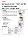
Fujitsu FTP-639MCL Thermal printer
• 3” paper width
• Serial RS232 interface
Source:
http://www.ipcprint.com
Cost:
approx. $350.00
Infinite Peripherals SPU-230-24IP
• AC power in 24VDC power out
Source:
http://www.ipcprint.com
Cost:
$69.00
APC BK650MC
• 650VA/400W
Source:
http://www.newegg.com
Price:
$100.00
Software
The client software has been completely implemented using the C++ language, and
was developed in the Microsoft Visual Studio .NET 2003 integrated development
environment. The software is currently undergoing a second round of system tests,
which is detailed later in this document.
The client was implemented as a programmed state machine that runs certain routines
based upon the state that it is in and then determines the next state based on user
inputs. The basic structure is illustrated below. The most basic state is a simple menu
in which the user is presented with several numbered options. The state machine loop
awaits the users selection, which is accomplished by pressing a single number key, then
uses information stored in the states collection to determine which state to go to next.
More complex states call functions that perform tasks as complicated as prompting a
user for a desired stall expiration time, calculating the cost of that amount of time,
prompting the user for coins, calculating the time paid for, and then printing a receipt.
Regardless of the complexity, the state machine handles the chore.
17
Figure 7 – Client Software Block Diagram
18
The main parkingMeter.exe
application runs in a console
window and coordinates several
software modules together,
including custom classes and
modules for hardware I/O, user
interaction, and other utility
functions. These functions are
described below.
Figure 8 – parkingMeter.exe Screenshot
Client Software Module Hierarchy
Below is the hierarchy for the client software.
•
ParkingMeter.exe – Main Client Program
¡
parkingMeter.cpp – state machine loop
¡
stateAction.cpp – calls helper functions based on current state
¡
states.ini – initialization text file containing state information in a serialized form.
The StateCollectionType class includes a member function for parsing this file
into a series of StateType objects for use in the parkingMeter.cpp module
¡
Custom Internal Classes
§ StateType.cpp – state information object
§ StateCollectionType.cpp – dynamic collection of state types object
¡
Input and Output
§ CoinDriver.cpp – translates coin acceptor inputs into key presses (runs as a
separate thread)
§ Coins.cpp – routines that prompt user for coin entry
§ Comport.cpp – freely available class for interacting with a serial port (used in
CoinDriver.cpp)
§ IOenable.h – contains global constant indicating whether or not to load
CoinDriver and LCDDriver
§ LCD.cpp – utility functions for displaying text to the LCD module
§ LCDDriver.cpp – hardware driver to display text on LCD module
§ Printing.cpp – utility functions for sending text to the printer
¡
User Interface
§ Admin.cpp – state and utility functions for the administrator menu options
§ Customer.cpp – state and utility functions for customer menu options
§ RateCalc.cpp – utility functions for calculating the monetary amounts due for
customers
§ Supervisor.cpp – state and utility functions for supervisor menu options
19
§
¡
userInput.cpp – utility functions for getting complex user input (e.g. dates,
times, other numbers)
Utilities
§ InterruptTimer.cpp – calls functions periodically for system updates and
server-client time synchronization (runs as a separate thread)
•
DateTimeType.dll – Custom Date and Time Object (used by ParkingMeter,
ParkingServerComm, and RateCollectionType classes)
¡
DateTimeType.cpp – contains all member and friend functions for the
DateTimeType class
¡
This class is a wrapper the ANSI C time.h
•
RateCollectionType.dll – Custom collection class for storing a rate
schedule
¡
RateType.cpp – RateType object that stores information for each rate period in a
rate schedule
¡
RateCollectionType – dynamic collection of RateType objects
•
ParkingServerComm.dll – Routines for setting and retrieving data from
the server unit (Developed primarily by the Dec04-02 team)
¡
MySQL++ - an open source API for interfacing C++ with a MySQL server (not
developed by project team)
¡
ParkingServerComm.cpp – utilizes MySQL++ to implement parking meter server
interaction routines
§ all routines are implemented in a single file in order to access a global server
connection object, but are categorized as follows
• Authentication – functions for authenticating users for supervisory or
administrative access
• Calendar – functions for setting and retrieving calendar information
• Rates – functions for setting and retrieving rate pricing and scheduling
information
• Stall – functions for getting and setting a stall’s expiration time and for
adding and removing stalls from the system
• Statistics – functions for generating statistical reports for printing
• User – functions for adding and removing user authentications
• Utilities – functions fitting no other category
20
Simulator
In order to facilitate software development on the parking meter without necessarily
using the actual server and client units, a hardware simulator was developed using
Visual Basic .NET.
Figure 9 – Screenshot of User Interface
VB.NET was chosen
both for its familiarity
to the project team
leader and its ease of
graphical
user
interface
development.
The
program provides a
simulated
LCD
character module of 4
lines
by
40
characters,
a
simulated console for
debugging outputs,
and
a
simulated
printer output spool.
The simulator works
by reading text files
generated
by
parkingMeter.exe
concurrently with LCD, printer, and console outputs. The executable is WinParking.exe
and must be run in the same directory as parkingMeter.exe.
17. Testing and Modification Activities
Since the last version of this document, much testing has been done on the prototype
unit. All of the hardware was hooked up and was confirmed to be working well
together. After hardware testing, initial client interface testing began. This consisted of
going through all of the states and ensuring that the menu options led to the proper
“next menu” or state as described in the software functional document (SFD).
The first round of testing was completed in late February/early March so that program
functionality specific bugs could be fixed as well as discover any bugs that may crash
the program, causing it to become inoperable. These tests were the first to test both
the server side of the software (or the database) with the client side and were designed
to ensure that every function worked as described in the SFD. The test situations were
developed by the Dec05-02 team and were distributed to each member of the Dec0502 and May05-02 team in order to complete the testing in a timely manner. Figure 10
shows an example of one of the test situations.
21
Figure 10 – Example of Test Cases
If a certain test fails for whatever reason (ranging from a program crash all the way
down to a simple interface glitch) the failure is documented in the “Note:” section of the
testing document with a detailed description of what exactly was wrong with the result
of the test.
After each tester is done with their section of tests, they input any failures into a bug
log—a spreadsheet used to simply track bugs and can be “checked off” when that bug
has supposedly been fixed. Figure 11 shows an example of a portion of this log.
22
23
Figure 11 – Example of bug log
For each bug found on a given test, each member will have to record the bug name
(which test case from which the bug came), the bug ID (to keep track of specific bugs)
a detailed explanation indicating the specific problem, and a proposed solution to the
bug in the spread sheet. (See Figure 12) When the bug is fixed, the person that fixed
the bug will denote this along with the date that the bug was fixed.
The project teams have recently finished the first round of testing and have fixed most
of the problems found thus far. A second round of testing has begun in order to further
test the prototype and ensure that there are no bugs. This process will continue until
all major bugs in the software are eliminated.
Following this, the prototype unit will be moved to a parking lot and tested outside with
real customers and administrator/supervisors. Customers will have the opportunity to
leave any feedback and/or suggestions for improvements to the design teams by filling
out the form found in Appendix B. Administrators and supervisors will be able to
directly contact the teams for support and suggestions.
18. Estimated Resources and Schedule
This section will provide an estimate of the resources required for the project and the
project schedules. The effort that will be spent on the project has been divided into
tasks as listed below.
•
•
•
•
•
•
•
•
Task 1: Project Familiarization
Task 2: Low-Level Slave Design
• Subtask 2.1: User Interface Flowcharts
• Subtask 2.2: Class and Function Descriptions
• Subtask 2.3: Block Diagram
Task 3: Slave Implementation and Unit Testing
• Subtask 3.1: Class Implementation
• Subtask 3.2: Function Implementation
• Subtask 3.3: Main Function Implementation
• Subtask 3.4: Hardware Implementation
Task 4: System Integration
Task 5: System Testing
Task 6: Bug Analysis and Removal
Task 7: Demonstration
Task 8: Documentation, Literature
24
Table 5 – Personnel Effort Requirements (revised)
Personal Effort (in hours)
Name
Task 2
Task 3
Task 1 2.1
2.2 2.3 3.1
3.2
Christopher Dasch 10
4
11 9
9
38
Ted Kwan
8
3
7
7
7
41
Jesse Pink
18
9
4
6
3
15
Andrew Ross
0
0
0
0
0
0
Pete Stoltenow
14
11
7
6
6
30
Subtotal Hours 50
27
29 28 25
124
Total Hours
50
84
306
Table 6 – Other Resource Requirements
Equipment and Other Resources
Item
Team Hours
Motherboard/Processor 1
0
RAM 1
0
Storage 1
0
Motherboard/Processor 2
0
RAM 2
0
Storage 2
0
LCD
0
Keypad
0
Misc. Buttons
0
Printer Controller
0
Ethernet Switch
0
UPS Battery Backup Unit
0
Housing
0
Project Poster
10
TOTAL
10
Total
3.3
35
27
30
0
35
127
3.4
5
2
8
0
15
30
Task 4
36
0
2
0
20
58
58
Task 5
0
17
18
13
14
62
62
Task 6
65
0
0
0
0
65
65
Task 7
5
5
5
5
5
25
25
Task 8
8
12
37
15
10
82
82
235
136
155
33
173
732
732
Cost
$150.00
$50.00
$200.00
$150.00
$50.00
$200.00
$75.00
$100.00
$50.00
$120.00
$57.00
$100.00
$0.00
$50.00
$1,352.00
25
Table 7 -- Financial Requirements
Item
Parts and materials
Motherboard/Processor 1
RAM 1
Storage 1
Motherboard/Processor 2
RAM 2
Storage 2
LCD
Keypad
Misc. Buttons
Printer Interface
Ethernet Switch
UPS Battery Backup Unit
Housing
Project Poster
Services
Shipping and handling
Binding
Equipment subtotal
Labor ($10.75 / hour)
Christopher Dasch
Ted Kwan
Jesse Pink
Pete Stoltenow
Previous Group Labor
Labor subtotal
TOTAL (With Labor)
Cost
$150.00
$50.00
$200.00
$150.00
$50.00
$200.00
$75.00
$100.00
$50.00
$120.00
$57.00
$100.00
$100.00
$0.00
$50.00
$50.00
$30.00
$1,532.00
$2,053.25
$1,892.00
$1,978.00
$1,988.75
$10,000.00 (estimate)
$17,912.00
$19,444.00
Schedule
Since May05-02 team has inherited this project from two previous teams, the schedule
for this team starts in the later design phase. Some of the project deliverables will
therefore be delivered in mid-implementation, though they may need to completed at
an accelerated pace.
Included below is a Gantt chart describing the expected project schedule over the next
two semesters, with a complete prototype built and tested by the end of the second
semester.
26
27
Figure 12 -- Gantt chart, Project deliverables
28
Figure 13 -- Gantt chart, Project tasks and subtasks
19. Lessons Learned
Successes
The project group learned how to successfully implement another team’s design,
and how to integrate our own design with theirs. The group also learned once
completed, the project requirements and design should remain static. To
attempt to change either one would push the project time table back, and the
project would never be completed.
Challenges
Communication between project groups and members was a reoccurring
problem. One group or member would have information that another one would
need, and that information would not be shared. The group needs to make itself
available at all times to other members, and respond to requests for information
quickly.
Technical Knowledge gained
Due to this project, the group has successfully learned several pieces of
software. These include Microsoft Project, Microsoft Visio, Microsoft Visual
Studio .NET, Microsoft Windows XP Embedded and mySQL.
Non-technical Knowledge gained
The project group has learned about the importance of documentation on any
project. Without proper documentation from the previous group, the group
would not have gotten far. Also learned was the importance of attending project
meetings. Meetings are not of much use if all members are not in attendance.
Possible changes if done again
If the project design could be done over again, the group would make a few
changes. First of all more attention should have been paid to the previous
team’s (Dec0402) documentation. Often the group would have questions about
the project that had already been answered in writing. Also, the project group is
in the unique situation of designing and implementing the project in one
semester, in order to combine the work with the other group. The group has
learned that integration takes more time than one would have thought, and the
group should schedule appropriately.
Also, documentation should be developed continually throughout the project.
Many times the team found themselves writing documentation days and hours
29
before it was due to be complete, which lessened its quality and heightened
stress on team members.
20. Risk and Risk Management
A number of potential risks have been identified:
Code integration
All code implementation will divide into several parts for each member. Even
though the group will have a plan to go by, it is possible that compatibility
problems may occur when putting the code together due to different format and
variables. Moreover, different writing style may lower the code readability and
affect the correction time. Deciding on the variables and styles that the group
will be using ahead of time (before actually writing any code) will mitigate this
risk. Also, any additional function or information must be reported to every
member.
Equipment damage
Unintended damage to project hardware components will take a toll in both time
and replacements costs. Properly handling and storing all equipment will mitigate
this risk.
Equipment Availability
Essential hardware may not be available for some unforeseen reason. Many of
the items used are produced in low volume and are not always readily available.
This risk will be mitigated by thoroughly researching hardware selections. The
hardware that has been chosen will most likely provide the type of requirements
that the group need.
Loss of a Team Member
Should a team member leave the university or lose his life, the effect on the
project should be minimal. Each team member will keep a detailed record of
their efforts, so that their work can be continued by someone else.
30
21. Project team information
The following is all the contact information for the client, faculty advisors, and the team
members working on the project.
Client
Doug Houghton
Captain
Department of Public Safety
31 Armory Building
Ames, IA 50011
Vox: 515/294-1987
Fax: 515/294-0383
[email protected]
Faculty
Advisors
Dr. John Lamont
324 Town Engineering
Iowa State University
Ames, IA 50010
Vox: 515/294-3600
Fax: 515/294-6760
[email protected]
Team
Members
Professor Ralph Patterson III
326 Town Engineering
Iowa State University
Ames, IA 50010
Vox: 515/294-2428
Fax: 515/294-6790
[email protected]
Chris Dasch
218 S Walnut No 5
Ames, IA 50010
[email protected]
Jesse Pink
4611 Mortensen Rd. #212
Ames, IA 50014
[email protected]
Andrew Ross
1300 Coconino Rd. #105
Ames, IA 50014
[email protected]
Peter Stoltenow
4226 Frederiksen Court
Ames, IA 50010
515/572-7860
[email protected]
Kwan Sin Wing Ted
1300 Gateway Hills #311
Ames, IA 50014
515/441-0224
[email protected]
31
22. Closing Summary
Parking has become a growing problem with more and more automobiles on the road.
In densely populated areas such as urban centers and corporate and academic
campuses, the problem is only worse. As Iowa State works to cope with its parking
predicament, it also needs a cost-effective solution to finance the construction and
maintenance of new lots. Current multi-space pay-for-parking systems are too
expensive and rigid to meet university needs, and old-style individual parking meters
are inefficient for a large number of parking spaces. The parking meter system
implemented in this project allows for easy and flexible administration of large parking
areas, saving resources and consequently increasing revenue.
23. References
Prototype Parking Metering System – Phase 2: Design Document. – Dec 04-02,
6 April 2004
http://seniord.ece.iastate.edu/dec0402/Dec04-02%20Design%20Document.pdf
Software Functional Description. – Dec 04-02, J. Lamont & R. Patterson III,
19 July 2004
32
Appendix A
Parking Enforcement Officer Evaluation Form
Tester Name:___________________________ Date Completed:_________________
Tester Phone #:__________________ Tester Email Address:___________________
Instructions:
The purpose of this test is to evaluate the use of this system to monitor and enforce parking lot
payments. Before completing the survey below, complete the following tasks:
1) Print the list of paid and unpaid stalls for enforcement.
2) Empty the coin box and retrieve the auditing receipt.
3) Print the diagnostics report.
Please circle the number that best describes your response as follows:
1 – Very Poor
2 – Poor
3 – Indifferent
4 – Good
5 – Excellent
Were the instructions clear and easy to understand?
1 2 3 4 5
Was it clear and easy how to print the enforcement receipt?
1 2 3 4 5
Did the enforcement receipt have all of the information that you needed? If
not, please comment on what info was missing.
Did the auditing receipt print when you opened the unit to empty the coin
box?
Did the auditing receipt that printed when you opened the coin box have the
information that you desired? If not, please comment on what info was
missing.
Were you easily able to print a diagnostic report?
Did the diagnostic report contain all of the information that you thought was
needed?
Were the key inputs easy to use?
1 2 3 4 5
1 2 3 4 5
1 2 3 4 5
1 2 3 4 5
1 2 3 4 5
1 2 3 4 5
Did the instructions clearly indicate which keys you were to press?
1 2 3 4 5
What is your overall impression of this machine
1 2 3 4 5
Please provide any additional comments or suggestions on the back of this form
33
Appendix B
Patron Evaluation Form
Tester Name:___________________________ Date Completed:_________________
Tester Phone #:__________________ Tester Email Address:___________________
Instructions:
The purpose of this test is to evaluate the use of the parking meter. Before completing the survey
below, please complete the following tasks:
1) Pay for a parking space by entering coins first and not by choosing the amount of time you
would like to pay for.
2) Add time to the parking space by entering the time you would like to pay for and then
depositing coins.
3) Complete the above transactions with and without printing a receipt.
5) Attempt to cancel the sale before you insert coins.
Please circle the number that best describes your response as follows:
1 – Very Poor
2 – Poor
3 – Indifferent
4 – Good
5 – Excellent
Were the instructions clear and easy to understand?
1 2 3 4 5
Was it clear and easy how to enter the stall number?
1 2 3 4 5
Was it clear and easy to enter the coins first and not choose the amount of time
1 2 3
for payment?
Was it clear and easy to choose the amount of time to pay for and then insert
1 2 3
coins?
Was it clear and easy to print a receipt?
1 2 3
Did the receipt have all of the information that you thought was necessary? If
1 2 3
not, please comment on what was missing.
Were you able to cancel the transaction before depositing coins?
1 2 3
4 5
4 5
4 5
4 5
4 5
Were the key inputs easy to use?
1 2 3 4 5
Did the instructions clearly indicate which keys you were to press?
1 2 3 4 5
What is your overall impression of this machine
1 2 3 4 5
Please provide any additional comments or suggestions on the back of this form
34