1
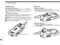
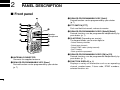
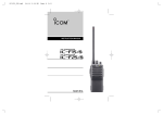
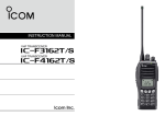
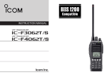
INSTRUCTION MANUAL
VHF TRANSCEIVERS
iF3021T/S
iF3023T/S
iF3026T/S
UHF TRANSCEIVERS
iF4021T/S
iF4023T/S
iF4026T/S
This device complies with Part 15 of the FCC Rules. Operation is
subject to the condition that this device does not cause harmful
interference.
The photo shows the 10-key
version VHF transceiver.
IMPORTANT
PRECAUTIONS
READ ALL INSTRUCTIONS carefully and com-
R CAUTION! NEVER hold the transceiver so that the
pletely before using the transceiver.
antenna is very close to, or touching exposed parts of the
body, especially the face or eyes, while transmitting. The
transceiver will perform best if the microphone is 2 to 4 in. (5
to 10 cm) away from the lips and the transceiver is vertical.
SAVE THIS INSTRUCTION MANUAL — This
instruction manual contains important operating instructions
for the IC-F3021T/S, IC-F3023T/S, IC-F3026T/S VHF
TRANSCEIVERS and the IC-F4021T/S, IC-F4023T/S, ICF4026T/S UHF TRANSCEIVERS.
R CAUTION! NEVER operate the transceiver with a
headset or other audio accessories at high volume levels.
R CAUTION! NEVER short the terminals of the bat-
EXPLICIT DEFINITIONS
tery pack.
DO NOT push [PTT] when not actually desiring to transWORD
DEFINITION
Personal injury, fire hazard or electric shock
RWARNING may occur.
CAUTION
NOTE
Equipment damage may occur.
If disregarded, inconvenience only. No risk
of personal injury, fire or electric shock.
Icom, Icom Inc. and the
logo are registered trademarks of Icom
Incorporated (Japan) in the United States, the United Kingdom, Germany,
France, Spain, Russia and/or other countries.
i
mit.
AVOID using or placing the transceiver in direct sunlight or
in areas with temperatures below +22°F (–30°C) or above
+140°F (+60°C).
The basic operations, transmission and reception of the transceiver are guaranteed within the specified operating temperature range. However, the LCD display may not be operate
correctly, or show an indication in the case of long hours of
operation, or after being placed in extremely cold areas.
DO NOT modify the transceiver for any reason.
KEEP the transceiver from the heavy rain, and
Never
immerse it in the water. The transceiver construction is water
resistant, not waterproof.
The use of non-Icom battery packs/chargers may impair
transceiver performance and invalidate the warranty.
For U.S.A. only
CAUTION: Changes or modifications to this transceiver, not
expressly approved by Icom Inc., could void your authority to
operate this transceiver under FCC regulations.
ii
TABLE OF CONTENTS
IMPORTANT ........................................................................ i
EXPLICIT DEFINITIONS ..................................................... i
PRECAUTIONS ................................................................... i
TABLE OF CONTENTS ...................................................... iii
1 ACCESSORIES ......................................................... 1–3
■ Supplied accessories ................................................. 1
■ Accessory attachments .............................................. 1
2 PANEL DESCRIPTION ............................................. 4–9
■ Front panel ................................................................. 4
■ Function display ......................................................... 6
■ Programmable function keys ..................................... 7
3 BASIC OPERATION ............................................. 10–15
■ Turning power ON .................................................... 10
■ Channel selection ..................................................... 11
■ Call procedure ........................................................... 11
■ Receiving and transmitting........................................ 12
■ User Set mode .......................................................... 14
■ Emergency transmission .......................................... 14
■ Scrambler function .................................................... 14
■ Stun function ............................................................ 15
■ Priority A channel selection ...................................... 15
4 BATTERY CHARGING .......................................... 16–20
■ Caution ..................................................................... 16
■ Optional battery chargers ......................................... 18
5 BATTERY CASE ......................................................... 21
■ Optional battery case (BP-240) ................................ 21
iii
6 OPTIONAL SWIVEL BELT CLIP .......................... 22–23
■ MB-93 contents ........................................................ 22
■ Attaching .................................................................. 22
■ Detaching ................................................................. 23
7 OPTIONS ............................................................... 24–25
8 SAFETY TRAINING INFORMATION .................... 26–27
ACCESSORIES
■ Supplied accessories
NOTE: Some accessories are not supplied with depending
on versions.
Flexible antenna
Battery pack
Belt clip
Jack cover
(with screws)
Unit cover
(double-sided tape)*
1
■ Accessory attachments
1
D Flexible antenna
Connect the supplied flexible antenna to the antenna connector.
CAUTION!
• NEVER HOLD the antenna
when carrying the transceiver.
• Transmitting without an antenna
may damage the transceiver.
*Use the unit cover as a spare. Ask your dealer for details.
1
1
ACCESSORIES
ï Battery pack
D Belt clip
To attach the battery pack:
Slide the battery pack in the direction of the arrow (q), then
lock it with the battery release button.
To attach the belt clip:
q Release the battery pack if it is attached.
w Slide the belt clip in the direction of the arrow until the belt
clip is locked and makes a ‘click’ sound.
• Slide the battery pack until the battery release button makes a ‘click’
sound.
To release the battery pack:
Slide the battery release button in the direction of the arrow
(w) as shown below. The battery pack is then released.
NEVER release or attach the battery pack when the transceiver is wet or soiled. This may result water or dust getting into the transceiver/battery pack and may result in the
transceiver being damaged.
To detach the belt clip:
q Release the battery pack if it is attached.
w Pinch the clip (q), and slide the belt clip in the direction of
the arrow (w).
w
q
q
Battery release button
w
2
ACCESSORIES
1
ï Jack cover
1
Attach the jack cover when the optional speaker-microphone
or headset is not used.
To attach the jack cover:
q Attach the jack cover to the [MIC/SP] jack.
w Tighten the screws.
To detach the jack cover:
q Unscrew the screws using a phillips screwdriver.
w Detach the jack cover for the speaker-microphone or
headset connection.
[MIC/SP] jack
q
q
w
Jack cover
w
q
CAUTION!
• Attach the jack cover when the optional speaker-microphone or headset is not used.
• Use the supplied screws only.
3
2
PANEL DESCRIPTION
■ Front panel
e DEALER-PROGRAMMABLE KEY [Side1]
Desired function can be programmed by your dealer.
(p. 7)
!0
q
w
e
o
r
Speaker
Microphone
t
i
u
y
q ANTENNA CONNECTOR
Connects the supplied antenna.
w DEALER-PROGRAMMABLE KEY [Emer]
Desired function can be programmed by your dealer.
(p. 7)
4
r PTT SWITCH [PTT]
Push and hold to transmit; release to receive.
t DEALER-PROGRAMMABLE KEYS [Side2]/[Side3]
Desired functions can be programmed independently by
your dealer. (p. 7)
y 10-KEYPAD (Depending on version)
The keypad allows you to enter digits to:
• Select memory channels
• Select tone channels
• Select DTMF codes (during transmit)
• Set TX codes
• Start up with the password
u DEALER-PROGRAMMABLE KEYS [P0] to [P3]
Desired functions can be programmed independently by
your dealer. (p. 7)
i FUNCTION DISPLAY (p. 6)
Displays a variety of information such as an operating
channel number/name, 2-tone code, DTMF numbers,
selected function, etc.
PANEL DESCRIPTION
2
2
o EXTERNAL MICROPHONE/SPEAKER JACK
Connect an optional speaker-microphone or headset.
NOTE: Connect or disconnect the optional equipment
after the transceiver is turned OFF.
Jack cover
NOTE: Attach the jack
cover when the optional
equipment is not used.
See (p. 3) for details.
!0 VOLUME CONTROL [VOL]
Rotate to turn the power ON/OFF and adjusts the audio
level.
5
2
PANEL DESCRIPTION
■ Function display
qw
e
r t
y u
y SCRAMBLER INDICATOR
Appears when the voice scrambler function is activated.
i
o
!0
q TRANSMIT INDICATOR
Appears while transmitting.
w BUSY INDICATOR
Appears while the channel is busy.
e SIGNAL STRENGTH INDICATOR
Indicates relative signal strength level.
r LOW POWER INDICATOR
Appears when low output power is selected.
• When the battery power decreases to a specified level, low
power is selected automatically.
t AUDIBLE INDICATOR
➥ Appears when the channel is in the ‘audible’ (unmute)
condition.
➥ Appears when the specified 2-tone code is received.
6
u BELL INDICATOR
Appears/blinks when the specific 2-tone code is received,
according to the pre-programming.
i KEY LOCK INDICATOR
Appears during the key lock function is ON.
o BATTERY INDICATOR
Appears or blinks when the battery power decreases to a
specified level.
!0 ALPHANUMERIC DISPLAY
Displays an operating channel number, channel name, Set
mode contents, DTMF code, etc.
PANEL DESCRIPTION
2
■ Programmable function keys
The following functions can be assigned to [Emer], [Side1],
[Side2], [Side3], [P0], [P1], [P2] and [P3] programmable
function keys.
Consult your Icom dealer or system operator for details concerning your transceivers programming.
If the programmable function names are bracketed in the following explanations, the specific key is used to activate the
function depends on the programming.
CH UP AND DOWN KEYS
➥ Push to select an operating channel.
➥ Push to select a transmit code channel after pushing [TX
Code CH Select].
➥ Push to select a DTMF channel after pushing [DTMF
Autodial].
➥ Push to select a scan group after pushing and holding
[Scan A Start/Stop]/[Scan B Start/Stop] for 1 sec.
ZONE KEY
Push this key, then push [CH Up] or [CH Down] to select the
desired zone.
What is “zone”?— The desired channels are assigned
into a zone according to the intended use for grouping. For
example, ‘Staff A’ and ‘Staff B’ are assigned into a
“Business” zone, and ‘John’ and ‘Cindy’ are assigned into a
“Private” zone.
2
SCAN A KEY
➥ This key’s operation depends on the Power ON Scan setting.
When the power ON scan function is turned OFF;
Push to start and cancel scanning operation. In case of
transmission during scan, scanning will be cancelled.
When the power ON scan function is turned ON;
Push to pause scanning, then resumes scanning after
passing a specified time period. In case of transmission
during scan, scanning will be cancelled.
➥ Push and hold this key for 1 sec. to indicate the scan
group, then push [CH Up] or [CH Down] to select the
desired group.
SCAN B KEY
➥ Push to start and cancel scanning operation. In case of
transmission during scan, scanning will be paused. Then
resumes scanning after passing a specified time period.
➥ Push and hold this key for 1 sec. to indicate the scan
group, then push [CH Up] or [CH Down] to select the
desired group.
SCAN ADD/DEL (TAG) KEY
Push to add or delete the selected channel to/from the scan
group.
7
2
PANEL DESCRIPTION
PRIO A/B KEYS
➥ Push to select Priority A or Priority B channel.
➥ Push and hold [Prio A (Rewrite)] or [Prio B (Rewrite)] for 1
sec. to reassign the operating channel to Priority A or
Priority B channel.
C.TONE CH ENT KEY
Push to select the continuous tone channel using
[CH Up]/[CH Down] to change the tone frequency/code setting. The selected channel remains set as the continuous
tone channel until another channel is designated as such.
MR-CH 1/2/3/4 KEYS
Push to select memory channels 1 to 4 in the operating zone
directly.
TALK AROUND KEY
Push to turn the talk around function ON and OFF.
MONI KEY
Mute and release the CTCSS (DTCS) or 2-tone squelch
mute. Open any squelch/deactivate any mute while pushing
and holding this key.
LOCK KEY
➥ Push and hold for 1 sec. to electronically lock all programmable keys except the following:
[Call] (incl. Call A and Call B), [Moni] and [Emergency].
➥ Push and hold for 1 sec. again to turn the lock function
OFF.
HIGH/LOW KEY
Push to select the transmit output power temporarily or permanently, depending on the pre-setting.
• Ask your dealer for the output power level for each selection.
8
• The talk around function equalizes the transmit frequency to the
receive frequency for transceiver-to-transceiver communication.
WIDE/NARROW KEY
Push to toggle the IF bandwidth between wide and narrow.
DTMF AUTODIAL KEY
➥ Push to enter the DTMF channel selection mode. Then
select the desired DTMF channel using [CH Up]/[CH
Down].
➥ After selecting the desired DTMF channel, push this key to
transmit the DTMF code.
RE-DIAL KEY
Push to transmit the last-transmitted DTMF code.
PANEL DESCRIPTION
CALL KEYS
Push to transmit a 2-tone.
TX CODE CHANNEL UP/DOWN KEYS
Push to select a TX code channel directly.
• Call transmission is necessary before you call another station
depending on your signaling system.
• [Call A] and/or [Call B] may be available when your system employs
selective ‘Individual/Group’ calls. Ask your dealer which call is
assigned to each key.
SCRAMBLER FUNCTION
Push to toggle the voice scrambler function ON and OFF.
EMERGENCY KEY
Push and hold for a specified period to transmit an emergency call.
• If you want to cancel the emergency call, push (or push and hold)
the key again before transmitting the call.
• The emergency call is transmitted one time only or repeatedly until
receiving a control code depending on the pre-setting.
SURVEILLANCE KEY
Push to turn the surveillance function ON or OFF.
When this function is turned ON, the beep is not emitted and
the LCD backlight does not light when a signal is received or
a key is pushed, etc.
SIREN KEY
Push to emit a siren.
2
2
USER SET MODE KEY
➥ Push and hold for 1 sec. to enter user set mode.
• During user set mode, push this key to select an item, and
change the value or condition using [CH Up]/[CH Down].
➥ Push and hold this key for 1 sec. again to exit user set
mode.
User set mode is also available via the ‘Power ON function.’
Refer to (p. 14) also.
OPT OUT KEYS
Push to control the output signal level of the optional ports in
the optional unit connector.
OPT MOMENTARY KEYS
Controls the output signal level of the optional ports in the
optional unit connector while pushing and holding this key.
TX CODE CHANNEL SELECT KEY
Push to enter the ID code channel selection mode directly.
Then set the desired channel using [CH Up]/[CH Down].
(p. 13)
9
3
BASIC OPERATION
■ Turning power ON
Prior to using the transceiver for the first time, the battery
pack must be fully charged for optimum life and operation.
(p. 16)
q Rotate [VOL] to turn the power ON.
w If the transceiver is programmed for a start up password,
input the digit codes as directed by your dealer.
• 10-keypad can be used for password input depending on version:
• The keys in the table below can be used for password input:
• The transceiver detects numbers in the same block as identical.
Therefore “01234” and “56789” are the same.
[VOL]
D Battery type selection
The battery type must be selected according to the attaching
battery type when turning the transceiver ON.
Ask your dealer for details.
q Turn the power OFF.
w While pushing and holding [Emer] and [PTT], turn the
power ON with rotating [VOL] to toggle the attaching battery type.
• After the display appears, release [Emer] and [PTT].
• “DRY BATT” is displayed for about 3 sec. then “L” appears when
the battery case operation is selected. In this case, the transmit
output power is low.
• “LI-ION” is displayed for about 3 sec. when the Lithium-ion battery operation is selected.
Appears
[VOL]
KEY
[Side3]
[P0]/[P1]/
[P2]/[P3]
NUMBER
Side3
0
1
2
3
4
5
6
7
8
9
e When the “PASSWORD” indication does not clear after
inputting 4 digits, the input code number may be incorrect.
Turn the power off and start over in this case.
10
[Emer]
[PTT]
Dry battery mode
BASIC OPERATION
3
■ Channel selection
■ Call procedure
Several types of channel selections are available. Methods
may differ according to your system set up.
When your system employs tone signaling (excluding CTCSS
and DTCS), the call procedure may be necessary prior to voice
transmission. The tone signaling employed may be a selective
calling system which allows you to call specific station(s) only
and prevent unwanted stations from contacting you.
NON-ZONE TYPE:
Push [CH Up] or [CH Down] to select the desired operating
channel, in sequence; or, push one of [MR-CH 1] to [MR-CH
4] keys to select a channel directly.
ZONE TYPE:
Push [Zone], then push [CH Up] or [CH Down] to select the
desired zone.
AUTOMATIC SCAN TYPE:
Channel setting is not necessary for this type. When turning
power ON, the transceiver automatically starts scanning.
Scanning stops when receiving a call.
3
q Select the desired TX code channel or 2-tone code
according to your System Operator’s instructions.
• This may not be necessary depending on programming.
• Refer to page 13 for selection.
w Push the call key (assigned to one of the dealer programmable keys: [Emer], [Side1], [Side2], [Side3], [P0], [P1],
[P2] and [P3]) or [PTT].
e After transmitting a 2-tone code, the remainder of your
communication can be carried out in the normal fashion.
Selective calling
Non-selective calling
11
3
BASIC OPERATION
■ Receiving and transmitting
NOTE: Transmitting without an antenna may damage the
transceiver. See page 1 for accessory attachments.
Receiving:
q Rotate [VOL] to turn the power ON.
w Push [CH Up] or [CH Down] to select the conventional system channel, in sequence.
e When receiving a call, adjust the audio output level to a
comfortable listening level.
Transmitting:
Wait for the channel to become clear to avoid interference.
q Push [Call] when initiating a call from your side.
• Coded audio may be heard from the transceiver, then “ ”
appears.
• This operation may not be necessary depending on your signaling system. Ask your dealer for details.
w While pushing and holding [PTT], speak into the microphone at a normal voice level.
e Release [PTT] to return to receive.
IMPORTANT: To maximize the readability of your signal;
1. Pause briefly after pushing [PTT].
2. Hold the microphone 5 to 10 cm (2 to 4 inches) from
your mouth, then speak into the microphone at a normal
voice level.
12
D Transmitting notes
• Transmit inhibit function
The transceiver has several inhibit functions which restrict
transmission under the following conditions:
- The channel is in mute condition (‘Inaudible’ condition;
“ ” does not appear.)
- The channel is busy.
- Un-matched (or matched) CTCSS is received.
(Depending on the pre-setting.)
- The selected channel is a ‘receive only’ channel.
• Time-out timer
After continuous transmission for the pre-programmed time
period, the time-out timer is activated, causing the transceiver to stop transmitting.
• Penalty timer
Once the time-out timer is activated, transmission is further
inhibited for a period determined by the penalty timer.
BASIC OPERATION
3
D TX code channel selection
D DTMF transmission
If the transceiver has [TX Code CH Select] assigned to it, the
indication can be toggled between the operating channel
number (or name) and TX code channel number (or name).
When the TX code channel number (or name) is displayed,
[CH Up] or [CH Down] selects the TX code channel.
If the transceiver has [DTMF Autodial] assigned to it, the automatic DTMF transmission function is available. Up to 8 DTMF
channels are available.
USING [TX CODE CH SELECT] KEY:
q Push [TX Code CH Select]— a TX code channel number
(or name) appears.
w Push [CH Up] or [CH Down] to select the desired TX code
channel.
3
TO SELECT A TX CODE:
q Push [DTMF Autodial]— a DTMF channel appears.
w Push [CH Up] or [CH Down] to select the desired DTMF
channel.
e Push [DTMF Autodial] to transmit the DTMF code in the
selected DTMF channel.
• Push [TX Code CH Select] again to return to the operating channel number indication.
e Push [Call] to transmit the selected TX code.
USING [TX CODE CH UP]/[TX CODE CH DOWN] KEY:
If the transceiver has [TX Code CH Up] or [TX Code CH
Down] assignment, the programmed TX code channel can be
selected directly when pushed.
13
3
BASIC OPERATION
■ User set mode
■ Emergency transmission
User set mode is accessed at power ON and allows you to
set seldom-changed settings. In this case you can “customize” the transceiver operation to suit your preferences and
operating style.
When [Emergency Single] or [Emergency Repeat] is pushed,
an emergency signal is automatically transmitted for the specified time period.
Entering the user set mode:
q While pushing and holding [Side2] and [Side3], rotate
[VOL] to turn the power ON. Then, push and hold [P0] for 1
sec. to enter user set mode.
w Push [P0] several times to select the appropriate item.
Then push [CH Up] or [CH Down] to set the desired
level/condition.
• Available set mode functions are Backlight, Beep, Beep Level,
SQL Level, Mic Gain, Battery Voltage and Signal Moni.
e Rotate [VOL] to turn the power OFF to exit user set mode.
NOTE: User set mode is also available via a programmable function key. Refer to “USER SET MODE KEY.” (p. 9)
When [Emergency] is pushed, the DTMF emergency signal
is transmitted on the priority channel.
When [Emergency Single] or [Emergency Repeat] is pushed
for the specified time period, the DTMF emergency signal is
transmitted once or repeatedly on the emergency channel.
However, when no emergency channel is specified, the signal
is transmitted on the previously selected channel.
■ Scrambler function
The voice scrambler function provides private communication
between stations. The frequency inversion type is equipped
to all versions, moreover, the optional Rolling or Non-rolling
type can be available.
q Push [Scrambler] to turn the scrambler function ON.
•“
” appears.
w Push [Scrambler] again to turn the scrambler function
OFF.
•“
14
” disappears.
BASIC OPERATION
3
■ Stun function
When the specified ID, set as a killer ID, is received, the stun
function is activated.
3
When the killer ID is received, the transceiver switches to the
password required condition. Entering of the password via the
keypad is necessary to operate the transceiver again in this
case.
■ Priority A channel selection
When one of the following operations is performed, the transceiver selects the Priority A channel automatically.
Priority A is selected when;
• Clear down signal is received/transmitted
- Set the ‘Move to PrioA CH’ item as ‘Clear down.’
• Turning the power ON
The Priority A channel is selected each time the transceiver power is turned ON.
• Status call
The Priority A channel is selected when transmitting a status call.
15
4
BATTERY CHARGING
■ Caution
Misuse of Lithium-ion batteries may result in the following hazards: smoke, fire, or the battery may rupture.
Misuse can also cause damage to the battery or degradation of battery performance.
R DANGER! Use and charge only specified Icom battery
packs with Icom radios or Icom charger. Only Icom battery
packs are tested and approved for use and charge with Icom
radios or Icom charger. Using third-party or counterfeit battery packs or charger may cause smoke, fire, or cause the
battery to burst.
D Battery caution
R DANGER! DO NOT hammer or otherwise impact the battery. Do not use the battery if it has been severely impacted or
dropped, or if the battery has been subjected to heavy pressure. Battery damage may not be visible on the outside of the
case. Even if the surface of the battery does not show cracks
or any other damage, the cells inside the battery may rupture
or catch fire.
R DANGER! NEVER use or leave battery packs in areas
with temperatures above +60˚C (+140˚F). High temperature
buildup in the battery, such as could occur near fires or
stoves, inside a sun heated car, or in direct sunlight may
cause the battery to rupture or catch fire. Excessive temperatures may also degrade battery performance or shorten battery life.
R DANGER! DO NOT expose the battery to rain, snow, seawater, or any other liquids. Do not charge or use a wet battery. If the battery gets wet, be sure to wipe it dry before
using. The battery is not waterproof.
R DANGER! NEVER incinerate used battery packs since
internal battery gas may cause them to rupture, or may cause
an explosion.
R DANGER! NEVER solder the battery terminals or NEVER
modify the battery pack. This may cause heat generation, and
the battery may rupture, emit smoke or catch fire.
R DANGER! Use the battery only with the transceiver for
which it is specified. Never use a battery with any other
equipment, or for any purpose that is not specified in this
instruction manual.
R DANGER! If fluid from inside the battery gets in your eyes,
blindness can result. Rinse your eyes with clean water, without rubbing them, and see a doctor immediately.
16
BATTERY CHARGING
WARNING! Immediately stop using the battery if it emits an
abnormal odor, heats up, or is discolored or deformed. If any
of these conditions occur, contact your Icom dealer or distributor.
WARNING! Immediately wash, using clean water, any part of
the body that comes into contact with fluid from inside the battery.
WARNING! NEVER put the battery in a microwave oven,
high-pressure container, or in an induction heating cooker.
This could cause a fire, overheating, or cause the battery to
rupture.
CAUTION! Always use the battery within the specified temperature range for the transceiver (–30˚C to +60˚C; –22˚F to
+140˚F) and the battery itself (–20˚C to +60˚C; –4˚F to
+140˚F). Using the battery out of its specified temperature
range will reduce the battery’s performance and battery life.
CAUTION! Shorter battery life could occur if the battery is left
fully charged, completely discharged, or in an excessive temperature environment (above +45˚C; +113˚F) for an extended
period of time. If the battery must be left unused for a long
time, it must be detached from the radio after discharging.
You may use the battery until the battery indicator shows halfcapacity, then keep it safely in a cool dry place with the temperature between –20˚C to +25˚C (–4˚F to +77˚F).
4
D Charging caution
R DANGER! NEVER charge the battery pack in areas with
extremely high temperatures, such as near fires or stoves,
inside a sun heated car, or in direct sunlight. In such environments, the safety/protection circuit in the battery will activate,
causing the battery to stop charging.
4
WARNING! DO NOT charge or leave the battery in the battery charger beyond the specified time for charging. If the battery is not completely charged by the specified time, stop
charging and remove the battery from the battery charger.
Continuing to charge the battery beyond the specified time
limit may cause a fire, overheating, or the battery may rupture.
WARNING! NEVER insert the transceiver (battery attached
to the transceiver) into the charger if it is wet or soiled. This
could corrode the battery charger terminals or damage the
charger. The charger is not waterproof.
CAUTION! DO NOT charge the battery outside of the specified temperature range: BC-160 (0˚C to +45˚C; +32˚F to
+113˚F). Icom recommends charging the battery at +20˚C
(+68˚F). The battery may heat up or rupture if charged out of
the specified temperature range. Additionally, battery performance or battery life may be reduced.
17
4
BATTERY CHARGING
■ Optional battery chargers
ï Rapid charging with the BC-160
ï AD-106 installation
The optional BC-160 provides rapid charging of optional LiIon battery packs.
• An AC adapter (may be supplied with BC-160 depending on
version) or the DC power cable (OPC-515L/CP-17L) is additionally required.
q Install the AD-106 desktop charger adapter into the holder
space of the BC-119N/BC-121N.
w Connect the plugs of the BC-119N/BC-121N to the AD-106
desktop charger adapter with the connector, then install
the adapter into the charger with the supplied screws.
q AD-106
AC adapter
(Not supplied with
some versions.)
Connectors
Battery Transceiver
pack
Turn power OFF
w
Screws supplied
with the charger
adapter
Optional OPC-515L
(for 13.8 V power
source) or CP-17L
(for 12 V cigarette
lighter socket) can
be used instead of
the AC adapter.
18
Plugs
BATTERY CHARGING
4
ï Rapid charging with the BC-119N+AD-106
ï Rapid charging with the BC-121N+AD-106
The optional BC-119N provides rapid charging of battery
packs. The following items are additionally required.
• AD-106 charger adapter
• An AC adapter (may be supplied with BC-119N depending
on version) or the DC power cable (OPC-515L/CP-17L).
The optional BC-121N allows up to 6 battery packs to be
charged simultaneously. The following items are additionally
required.
• Six AD-106 charger adapters
• An AC adapter (BC-157) or the DC power cable (OPC-656)
Transceiver
Turn power OFF
4
Transceiver
Turn power OFF
Battery
pack
Battery
pack
AC adapter
(Purchased
separately)
AD-106 charger
adapters are installed
in each slot.
AC adapter
(Not supplied with
some versions.)
Optional OPC-515L (for 13.8 V
power source) or CP-17L (for
12 V cigarette lighter socket)
can be used instead of the AC
adapter.
AD-106 charger
adapter is installed
in BC-119N.
DC power cable (OPC-656)
(Connect with the DC power supply;
13.8 V/at least 7 A)
19
4
BATTERY CHARGING
IMPORTANT!: Battery charging caution
Ensure the guide lobs on the battery pack are correctly
aligned with the guide rails inside the charger adapter.
(This illustration is described with the BC-160.)
Lobs
Guide rail
20
5
BATTERY CASE
■ Optional battery case (BP-240)
When using the optional battery case, install 6 × AAA (LR03)
size alkaline batteries as illustrated at right.
Fig.1
w
BP-240
q Unhook the battery cover release hook (q), and open the
cover in the direction of the arrow (w). (Fig.1)
w Then, install 6 × AAA (LR03) size alkaline batteries. (Fig.2)
4
5
• Install the alkaline batteries only.
• Be sure to observe the correct polarity.
• Do not pin the ribbon under the batteries.
e Fit the cover in the direction of the arrow (e), then close
(r). And hook the battery cover release hook until it
makes a ‘click’ sound (t). (Fig.3)
CAUTION:
• When installing batteries, make sure they are all the same
brand, type and capacity. Also, do not mix new and old
batteries together.
• Keep battery contacts clean. It’s a good idea to clean battery terminals once a week.
• Never incinerate used battery cells since internal battery
gas may cause them to rupture.
• Never expose a detached battery case to water. If the battery case gets wet, be sure to wipe it dry before using it.
NOTE: When the optional battery case is attached, the
battery type must be selected to “DRY BATT” when turning the transceiver ON. (p. 10)
q
Fig.2
e
Fig.3
r
t
21
6
OPTIONAL SWIVEL BELT CLIP
■ MB-93 contents
Qty.
q Belt clip ……………………………………………………… 1
w Base clip …………………………………………………… 1
q
e Clip the belt clip to a part of your belt. And insert the transceiver into the belt clip until the base clip inserted fully into
the groove.
w
■ Attaching
r Once the transceiver is locked in place, it swivels as illustrated below.
q Release the battery pack if it is attached. (p. 2)
w Slide the base clip in the direction of the arrow until the
base clip is locked and makes a ‘click’ sound.
Once the transceiver is locked in place,
it will swivel 360 degrees.
22
OPTIONAL SWIVEL BELT CLIP
6
■ Detaching
q Turn the transceiver upside down in the direction of the
arrow and pull out from the belt clip.
w Release the battery pack if it is attached. (p. 2)
e Pinch the clip (q), and slide the base clip in the direction
of the arrow (w).
q
w
6
CAUTION!
HOLD THE TRANSCEIVER TIGHTLY, WHEN HANGING
OR DETACHING THE TRANSCEIVER FROM THE BELT
CLIP.
Otherwise the transceiver may not be attached to the holder or swivel properly if the transceiver is accidentally
dropped and the base clip is scratched or damaged.
23
7
OPTIONS
D BATTERY PACK
D BELT CLIPS
1
Battery pack
Voltage
Capacity
Battery life*
BP-230N
7.4 V
980 mAh
7.35 hrs.
BP-232N
7.4 V
2000 mAh
15.5 hrs.
BP-240
Battery case for AAA
(LR03) × 6 alkaline
—*2
*1 When the power save function is turned ON, and the operating periods are calculated under the following conditions;
TX : RX : standby = 5 : 5 : 90
*2 Operating period depends on the alkaline cells used.
D CHARGERS
•BC-119N DESKTOP CHARGER + AD-106 CHARGER ADAPTER
+ BC-145 AC ADAPTER
For rapid charging of battery packs. An AC adapter is supplied with the charger depending on versions. Charging
time: approx. 2 hours when BP-231 is attached.
•BC-121N MULTI-CHARGER + AD-106 CHARGER ADAPTER (6 pcs.)
+ BC-157 AC ADAPTER
For rapid charging of up to 6 battery packs (six AD-106’s are
required) simultaneously. An AC adapter should be purchased separately. Charging time: approx. 2 hours when
BP-231 is attached.
•BC-160 DESKTOP CHARGER + BC-145 AC ADAPTER
For rapid charging of battery packs. An AC adapter is supplied with the charger depending on versions. Charging
time: approx. 2 hours when BP-231 is attached.
24
• MB-93 SWIVEL BELT CLIP
• MB-94 BELT CLIP
Exclusive alligator-type belt clip. The same as supplied with
the transceiver.
• MB-96N/96F LEATHER BELT HANGER
D OPTIONAL UNITS
• UT-108R DTMF DECODER UNIT
Provides pager and code squelch capabilities.
• UT-109R /UT-110R* VOICE SCRAMBLER UNITS
Non-rolling type (UT-109R)/Rolling type (UT-110R)* voice
scrambler unit provides higher communication security.
*You can use the UT-110R as Non-rolling type.
D DC CABLES
• CP-17L CIGARETTE LIGHTER CABLE
Allows charging of the battery pack through a 12 V cigarette
lighter socket. (For BC-119N)
• OPC-515L/OPC-656 DC POWER CABLES
Allows charging of the battery pack using a 13.8 V power
source instead of the AC adapter.
OPC-515L: For BC-119N
OPC-656 : For BC-121N
OPTIONS
7
D OTHER OPTIONS
• SP-13 EARPHONE
Provides clear receive audio in noisy environment.
• HM-158L/159L SPEAKER-MICROPHONE
Combination speaker-microphone that provides convenient
operation while hanging the transceiver from your belt.
• HS-94/HS-95/HS-97 HEADSET + VS-1L VOX/PTT CASE
HS-94: Ear-hook type
HS-95: Neck-arm type
HS-97: Throat microphone
VS-1L: VOX/PTT switch box for hands-free operation, etc.
7
• FA-SC25V/FA-SC55V/
FA-SC25U/FA-SC57U/FA-SC72U ANTENNAS
FA-SC25V: 136–150 MHz
FA-SC55V: 150–174 MHz
FA-SC25U: 400–430 MHz
FA-SC57U: 430–470 MHz
FA-SC72U: 470–520 MHz
• FA-SC56VS/FA-SC57VS/FA-SC73US STUBBY ANTENNAS
FA-SC56VS: 150–162 MHz
FA-SC57VS: 160–174 MHz
FA-SC73US: 450–490 MHz
Some options may not available in some countries. Ask your dealer
for details.
25
8
SAFETY TRAINING INFORMATION
Your Icom radio generates RF electromagnetic
energy during transmit mode. This radio is
designed for and classified as “Occupational Use
Only”, meaning it must be used only during the
W ARN ING course of employment by individuals aware of the
hazards, and the ways to minimize such hazards.
This radio is NOT intended for use by the “General Population” in
an uncontrolled environment.
This radio has been tested and complies with the FCC RF exposure limits for “Occupational Use Only”. In addition, your Icom
radio complies with the following Standards and Guidelines with
regard to RF energy and electromagnetic energy levels and evaluation of such levels for exposure to humans:
• FCC OET Bulletin 65 Edition 97-01 Supplement C,
Evaluating Compliance with FCC Guidelines for Human
Exposure to Radio Frequency Electromagnetic Fields.
• American National Standards Institute (C95.1-1992), IEEE
Standard for Safety Levels with Respect to Human Exposure
to Radio Frequency Electromagnetic Fields, 3 kHz to 300
GHz.
• American National Standards Institute (C95.3-1992), IEEE
Recommended Practice for the Measurement of Potentially
Hazardous Electromagnetic Fields– RF and Microwave.
• The following accessories are authorized for use with this
product. Use of accessories other than those specified may
result in RF exposure levels exceeding the FCC requirements for wireless RF exposure.; Belt Clip (MB-94),
Rechargeable Li-Ion Battery Pack (BP-230N/BP-232N) and
Speaker-microphone (HM-159L/HM-158L).
26
To ensure that your expose to RF electromagnetic energy is within the FCC allowable limits
for occupational use, always adhere to the following guidelines:
C AU TIO N
• DO NOT operate the radio without a proper antenna
attached, as this may damaged the radio and may also
cause you to exceed FCC RF exposure limits. A proper
antenna is the antenna supplied with this radio by the manufacturer or antenna specifically authorized by the manufacturer for use with this radio.
• DO NOT transmit for more than 50% of total radio use time
(“50% duty cycle”). Transmitting more than 50% of the time
can cause FCC RF exposure compliance requirements to be
exceeded. The radio is transmitting when the TX indicator
lights red. You can cause the radio to transmit by pressing
the “PTT” switch.
• ALWAYS keep the antenna at least 2.5 cm (1 inch) away
from the body when transmitting and only use the Icom beltclips listed on page 24 when attaching the radio to your belt,
etc., to ensure FCC RF exposure compliance requirements
are not exceeded. To provide the recipients of your transmission the best sound quality, hold the antenna at least 5 cm
(2 inches) from your mouth, and slightly off to one side.
The information listed above provides the user with the information needed to make him or her aware of RF exposure, and what
to do to assure that this radio operates with the FCC RF exposure limits of this radio.
SAFETY TRAINING INFORMATION
8
Electromagnetic Interference/Compatibility
During transmissions, your Icom radio generates RF energy that
can possibly cause interference with other devices or systems.
To avoid such interference, turn off the radio in areas where signs
are posted to do so. DO NOT operate the transmitter in areas
that are sensitive to electromagnetic radiation such as hospitals,
aircraft, and blasting sites.
Occupational/Controlled Use
The radio transmitter is used in situations in which persons are
exposed as consequence of their employment provided those
persons are fully aware of the potential for exposure and can
exercise control over their exposure.
8
27
A-6506D-1EX-w
Printed in Japan
© 2006 Icom Inc.
1-1-32 Kamiminami, Hirano-ku, Osaka 547-0003, Japan