1
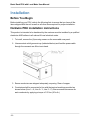
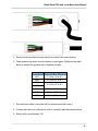
Panduit Basic Rack PDU
with Local Meter
User Manual
Release 1.0
Issue 1.0
Basic Rack PDU with Local Meter User Manual
Copyright © 2014 Panduit Corp. All rights reserved. No part of this book shall be reproduced, stored in a retrieval system, or transmitted
by any means, electronic, mechanical, photocopying, recording or otherwise, without written permission from Panduit. No patent liability
is assumed with respect to the use of the information contained herein.
Although every precaution has been taken in the preparation of this book, Panduit assumes no responsibility for errors or omissions.
Neither is any liability assumed for damages resulting from the use of the information contained herein.
-2-
Basic Rack PDU with Local Meter User Manual
Table of Contents
Basic Rack PDU with Local Meter
Contacting Panduit
Symbols Used
Equipment Overview
Model Numbering Format
Part Numbering Format
Pre-Installation
Product Inspection
Installation
Before You Begin
Hardwire PDU installation instructions
Unterminated Cord PDU installation instructions
Standard Accessories
Additional Required Items
Hardware
LCD Display
Reset Button
Mode Button Operation
Unit Startup
Unit Operation
4
4
4
5
5
6
7
7
8
8
8
10
10
10
11
11
11
11
11
12
-3-
Basic Rack PDU with Local Meter User Manual
Basic Rack PDU with Local Meter
Panduit Basic Rack PDUs with Local Meter provide reliable power distribution to
devices installed within a cabinet and have an on-unit display to allow for local monitoring of power information.
This equipment has been designed for connection to an IT power distribution system.
Contacting Panduit
For technical support on PDU hardware and associated software, please contact Panduit Technical Support using one of the following methods:
l
l
1-866-721-5302 (toll-free), Monday-Friday, 7:30 am - 5:00 pm CST
[email protected]
Symbols Used
Symbol
Description
Danger – Electric Shock Hazard
Warning – Possible Safety Hazard
Primary Earth Ground
Secondary Earth Ground
-4-
|
ON
O
OFF
Basic Rack PDU with Local Meter User Manual
Equipment Overview
The power inlet/cord(s) connects the PDU to the electrical power source. The LCD displays the current load for each input feed or electrical phase per input feed.
For IEC C-20 inlet PDUs, a customer-supplied cord is used for connection to the power
source. The connection end to the PDU has an IEC C-19 plug for connection to the
PDU. The opposite end of the cord has a plug suitable for connecting to the customer-supplied
receptacle. The cord and plug shall be rated for 20A in North America and 16A outside
of North America. Make the connection to the PDU before connecting to the power
source
Model Numbering Format
This section describes the model numbering format used to identify equipment in the
PDU series. PDU model numbers are:
l
l
l
l
HD-YYYVZZA
HE-YYYVZZA
VD-YYYVZZA
VE-YYYVZZA
The letters in the series represent values as defined in the table below.
Letter
H
What It Represents
Horizontal series
V
Vertical series
D
Basic - no monitoring or display provided
E
Metered - on board display only
YYY
ZZ
May be any number, 120-415, representing rated voltage
May be any number, 10-63, representing rated current
-5-
Basic Rack PDU with Local Meter User Manual
Part Numbering Format
This section describes the part numbering format used to identify equipment in the PDU
series. PDU devices are numbered using one of the following formats:
l
l
H1M-ABCDEFGHJKLM
V1M-ABCDEFGHJKLM
The H1M prefix indicates that the model is intended for horizontal mounting.
The V1M prefix indicates that the model is intended for vertical mounting.
The remaining letters in the series represent values as defined in the table below.
Letter
A
B
CD*
What It Represents
Any numeral, 1-8, indicating the phase wiring for the output circuit breakers and receptacles
Any letter, A-F, indicating input cord configuration
Any numeral, 1-5, and any letter, A-Z, indicating input plug type and
rated voltage
E
Any numeral, 1-7, indicating the number of output circuit breakers
F
Any letter, A-Z, indicating the type of overload protection provided for
the outlets
GH
Any two numerals, 01-45, indicating the number of output receptacles
provided
JK
The letter ‘A’ or ‘B’ followed by any letter, A-Z, indicating the type and
quantity of output receptacles provided
L
Any numeral, 0-9, or any letter, A-Z, indicating the length of the power
supply cord
M
Any numeral, 0-9, indicating the color of the enclosure
* Voltage and amperage ratings:
l
l
l
l
l
l
-6-
120V, single-phase, 10A, 12A, 15A, 16A, 20A, 24A or 30A
208V, single-phase, 10A, 12A, 13A, 15A, 16A, 20A, 24A, 30A, 48A or 60A
230V, single-phase, 16A, 32A, or 48A
208V, three-phase (delta), 16A, 20A, 24A, 30A, 40A, 48A, 50A or 60A, 3W + PE
208V, three-phase (wye), 16A, 20A, 24A, 30A, 48A or 60A, 3W + N + PE
400V, three-phase (wye), 16A, 20A, 24A, 30A, 32A, 48A or 60A, 3W + N + PE
Basic Rack PDU with Local Meter User Manual
Pre-Installation
The Rack PDU products covered by this guide are designed to be installed within EIA
racks and cabinets. Use of this product in other applications is acceptable, but other precautions may be required to allow for specific installations not covered by this guideline.
Product Inspection
Inspect the product prior to installation. If the product has any visible signs of damage,
please contact the supplier.
-7-
Basic Rack PDU with Local Meter User Manual
Installation
Before You Begin
Before installing your PDU, refer to the following lists to ensure that you have all the
items shipped with the unit as well as all other items required for proper installation.
Hardwire PDU installation instructions
This product is intended to be hardwired by the customer must be installed by a qualified
electrician AND adhere to all national & local electrical codes.
1. To install, remove the (4) securing screws on the removable user panel.
2. Unscrew strain relief grommet cap (indicated below) and feed the power cable
through the grommet cap & the input gland.
3. Ensure conductors are stripped adequately, exposing 15mm of copper.
4. Conductors shall be connected in-line with the terminal markings provided as
shown below (Line 1 = X; Line 2 = Y; Line 3 – Z). Ensure screws are secure for
each conductor by applying a torque of 2.3 N-m (20 in-lb.).
-8-
Basic Rack PDU with Local Meter User Manual
5. Ensure conductors have enough slack (none should be under tension).
6. Feed grommet cap down cord and secure to input gland. Reference the table
below to ensure the grommet cap is torqued correctly.
Gland Size Grommet Cap Torque
M16
1.5 N-m (13 in-lb.)
M20
3.0 N-m (27 in-lb.)
M25
M32
4.0 N-m (35 in-lb.)
M40
15 N-m (132 in-lb.)
M50
20 N-m (177 in-lb.)
M63
30 N-m (266 in-lb.)
7. Re-install removable cover plate with the screws removed in step 1.
8. Connect the other end of the power cord to a suitably rated disconnect device.
9. Switch utility circuit breaker “On”.
-9-
Basic Rack PDU with Local Meter User Manual
Unterminated Cord PDU installation instructions
This product is intended to be hardwired by the customer must be installed by a qualified
electrician AND adhere to all national & local electrical codes.
To install, match the corresponding conductor color to the matching phase in your facility. Reference the color guide below:
Conductor Insulation Color Line Number / Phase
Brown
Line1 / X
Black
Line 2 / Y
Grey
Line 3 / Z
Blue
Neutral
Green (may include Yellow stripe)
Ground
Standard Accessories
Mounting hardware:
l
l
Vertical models:
Affixed button mounts
Horizontal models:
Appropriate local mounting brackets and screws
Additional Required Items
l
l
- 10 -
Flathead and Phillips screwdrivers
Appropriate local AC power receptacle to power the PDU
Basic Rack PDU with Local Meter User Manual
Hardware
LCD Display
On metered PDUs, the display shows the device model number, serial number, and electrical readings. The display automatically scrolls through the readings. Below are the
readings that will be displayed:
l
l
l
l
l
l
Start up messages
Configuration/serial/product number messages
Error/Status messages
Aggregate data
Single-Phase data, 3-Phase Delta data, or 3-Phase Wye data
Branch Current data, if the unit has breakers
Reset Button
Push the Reset button using a non-metallic item, similar in size to a paper clip, to reset
the PDU device.
Warning: a metallic item, such as a paper clip, is not recommended as a reset
tool.
The reset tool should be inserted perpendicular to the surface of the device and pressed
until the button is reached and is actuated.
The reset tool should bump into the button within 1/8 of an inch of being inserted, and
should be lightly depressed and held for at least 1 second. The reset tool should never
be inserted more than 1/4 of an inch.
Resetting the PDU device starts the bootloader. Wait between 1 and 30 seconds for the
Display Backlight to blink on and off at a rate of 2 blinks per second. The bootloader
stays in this mode for at least 4 seconds (8 blinks) if no user operation is detected.
Mode Button Operation
Unit Startup
When the unit first starts up, the LCD backlight begins to blink. Avoid pressing the Mode
button until the LCD finishes blinking and the display backlight turns off.
- 11 -
Basic Rack PDU with Local Meter User Manual
When the application is ready, a message displays on the LCD:
Starting up…
The display backlight blinks quickly three times and remains lit. Avoid pressing the
Mode button until the firmware version is displayed.
Unit Operation
Once the firmware version is displayed, you can press the Mode button to move to the
next display screen.
- 12 -