Download CardEX - Veterinary Instrumentation
Transcript
Go To Table Of Contents CardEX 100 ™ Single Channel Electrocardiograph Manual Ver: V1.0 Release Date: July 2008 Revised Date; May 2009 Part Number: CDX-03-0199 Next Go To Table Of Contents Back EC Declaration of Conformity Manufactured for: Midmark Address: 10008 N. Dale Mabry Hwy, Suite 110, Tampa, FL 33618 Product: Electrocardiograph Model: CARDEX™ 100 We herewith declare that the above mentioned product(s) meet the standards listed below: EN 60601-1: 1988, EN 60601-2-25: 1995, EN 60601-1-2: 2001 CE Mark: -I- Next Go To Table Of Contents Back Copyright Copyright © Midmark Corporation 2009. All rights reserved. Statements Midmark Corporation (hereinafter called Midmark) makes no warranty of any kind with regard to this material, including, but not limited to the implied warranties of merchantability and fitness for a particular purpose. Midmark assumes no responsibility for any errors that may appear in this document, or for incidental or consequential damage in connection with the furnishing, performance or use of this material. No part of this document can be photocopied, reproduced or translated to another language without prior written consent of Midmark. Responsibility of the Manufacturer Midmark only considers itself responsible for effects on safety, reliability and performance of the equipment if: ♦ Assembly operations, extensions, re-adjustments, modifications or repairs are carried out by personnel authorized by Midmark; ♦ The electrical installation of the relevant room complies with safety standards; ♦ The instrument is used in accordance with the instructions for use. Note: This device is not intended for home use. WARNING : This device is not intended for treatment. Using This Label Guide WARNING A WARNING label advises against certain actions or situations that could result in personal injury or death. CAUTION A CAUTION label advises against actions or situations that could damage equipment, produce inaccurate data, or invalidate a procedure. Note: A NOTE provides useful information about a function or procedure. -II- Next Back Next Table of Contents 1 Safety Guidance...................................................................................................................... 5 1.1 Safety Information .......................................................................................................... 5 1.2 Warnings and Cautions ................................................................................................... 5 1.2.1 Safety Warnings .................................................................................................... 6 1.2.2 Battery Care Warnings .......................................................................................... 7 1.2.3 General Cautions................................................................................................... 8 1.2.4 Cleaning & Disinfection Cautions ......................................................................... 9 2 Introduction .......................................................................................................................... 10 2.1 Function Features ......................................................................................................... 10 2.2 List of Symbols ............................................................................................................ 11 3 General Information ............................................................................................................ 12 3.1 Top Panel...................................................................................................................... 12 3.1.1 LCD Screen ........................................................................................................ 12 3.1.2 Control Panel and Keys ....................................................................................... 14 3.2 Patient Cable Socket and Signal Interface ..................................................................... 17 3.3 Mains Connection and Switch....................................................................................... 19 3.4 Bottom Panel ................................................................................................................ 21 4 Operation Preparations ....................................................................................................... 23 4.1 Power Supply ............................................................................................................... 23 4.2 Loading/Replacing Recording Paper ............................................................................. 24 4.3 Patient Cable Connection .............................................................................................. 25 4.4 Electrode Connections .................................................................................................. 26 4.5 Inspection before Switching on ..................................................................................... 27 5 Operation Instructions ......................................................................................................... 29 5.1 Switching On ................................................................................................................ 29 5.2 Animal Information Input ............................................................................................. 29 5.3 Menu Settings ............................................................................................................... 30 5.3.1 Filter Settings ...................................................................................................... 31 5.3.2 Recording Settings .............................................................................................. 31 5.3.3 Date and Time Settings ....................................................................................... 32 5.3.4 Print Head Test.................................................................................................... 32 5.3.5 External Input/Output Settings ............................................................................ 32 5.3.6 Key and QRS Beep Settings ................................................................................ 33 5.3.7 Rhythm Lead Settings ......................................................................................... 33 -III- Back Go To Table Of Contents 5.4 Sensitivity Switching .................................................................................................... 33 5.5 Automatic Mode Operation ........................................................................................... 33 5.6 Manual Mode ............................................................................................................... 34 5.7 ECG Record ................................................................................................................. 35 5.8 Switch Off .................................................................................................................... 35 6 Alarm Information ............................................................................................................... 36 7 Technical Specifications ....................................................................................................... 37 8 Cleaning, Care and Maintenance ........................................................................................ 40 8.1 Cleaning ....................................................................................................................... 40 8.1.1 Cleaning the Main Unit and Patient Cable ........................................................... 40 8.1.2 Cleaning the Electrodes....................................................................................... 40 8.1.3 Cleaning the Print Head ...................................................................................... 40 8.2 Disinfection .................................................................................................................. 41 8.3 Care and Maintenance .................................................................................................. 41 8.3.1 Recharge and Replacement of Battery ................................................................. 41 8.3.2 Recording Paper.................................................................................................. 42 8.3.3 Maintenance of Main Unit, Patient Cable & Electrodes ....................................... 43 9 Service Warranty.................................................................................................................. 45 10 Accessories and Ordering Information.............................................................................. 46 -IV- Next Go To Table Of Contents Back 1 Safety Guidance 1.1 Safety Information The design of the single channel electrocardiograph complies with the international standard IEC 60601-1 Medical Electrical Equipment: General Requirements for Safety and IEC 60601-2-25 Particular Requirements for the Safety of Electrocardiographs etc. The classification of this equipment is Class І, type CF, which means a higher degree of protection against electric shock, and the patient connection is fully isolated. Furthermore it is defibrillation-proof. This equipment is not explosion-proof. Do not use it in the presence of flammable anesthetics. This equipment is designed for continuous operation however it is not drip or splash-proof. Classification: 1) Anti-electric-shock type: Class І with internal power supply 2) Anti-electric-shock degree: CF (with defibrillation-proof applied part) 3) Degree of protection against harmful ingress of water: Ordinary equipment (Sealed equipment without liquid proof) 4) Disinfection/sterilization method: Refer to this user manual for details 5) Safety degree of application in the presence of flammable gas: Equipment not suitable for use in the presence of flammable gas 6) Working Mode: Continuous operation 7) EMC: Group І 1.2 Warnings and Cautions In order to use the electrocardiograph safely and effectively, avoiding possible dangers caused by improper operations, please read through the user manual and be sure to be familiar with all functions of the equipment and proper operation procedures before use. Please pay attention to the following warning and caution information. -5- Next Go To Table Of Contents Back 1.2.1 Safety Warnings WARNING ♦ : The electrocardiograph is provided for the use of qualified physicians or personnel professionally trained. And they should be familiar with the contents of this user manual before operation. ♦ Only qualified service engineers can install this equipment. And only service engineers authorized by Midmark can open the shell. ♦ Only qualified installation or service engineers can shift the mains shift switch (100V~115V/220V~240V) according to local mains supply. ♦ The results given by the equipment should be examined with respect to the overall clinical condition of the animal. It cannot substitute for regular checking. WARNING ♦ : EXPLOSION HAZARD-Do not use the electrocardiograph in the presence of flammable anesthetic mixture with oxygen or other flammable agents. ♦ SHOCK HAZARD-The power receptacle must be a hospital grade grounded outlet. Never try to adapt the three-prong plug to fit a two-slot outlet. ♦ If the integrity of external protective conductor in installation or arrangement is in doubt, the equipment should be operated from the built-in rechargeable battery. ♦ Do not use this equipment in the presence of high static electricity or high voltage equipment which may generate sparks. ♦ This equipment is designed for direct cardiac application. WARNING ♦ : Only patient cable and other accessories supplied by Midmark can be used. Or else, the performance and electric shock protection cannot be guaranteed. ♦ Be sure that all electrodes have been connected to the animal correctly before operation. ♦ Be sure that the conductive parts of electrodes and associated connectors, including neutral electrode, should not contact with earth or any other conducting objects. -6- Next Go To Table Of Contents Back ♦ Electrodes with defibrillation protection should be used while defibrillating. ♦ There is no danger for animals with pacemaker. ♦ Do not touch the animal, bed, table and the equipment while using defibrillator or pacemaker simultaneously. ♦ In order to avoid burning, please keep the electrode far away from the radio knife while using electrosurgical equipment simultaneously. WARNING ♦ : Accessory equipment connected to the analog and digital interfaces must be certified according to the respective IEC standards (e.g. IEC 60950 for data processing equipment and IEC 60601-1 for medical equipment). Furthermore all configurations shall comply with the valid version of the standard IEC 60601-1-1. Therefore anybody, who connects additional equipment to the signal input connector or output connector to configure a medical system, must make sure that it complies with the requirements of the valid version of the system standard IEC 60601-1-1. If in doubt, consult our technical service department or your local distributor. ♦ The summation of leakage current should never exceed leakage current limits while several other units are used at the same time. ♦ The potential equalization conductor can be connected to that of other equipment when necessary, to make sure that all equipment is connected with the potential equalization bus bar of the electrical installation. 1.2.2 Battery Care Warnings WARNING ♦ : Improper operation may cause the battery to be hot, ignite or explode, and it may lead to the declination of battery’s capacity. It is necessary to read the user manual carefully and pay more attention to warning messages. ♦ Only a qualified service engineer authorized by Midmark can open the battery compartment and replace the battery. The battery of same model and specification provided by manufacturer should be used. ♦ Danger of explosion -- Do not reverse the anode and cathode when connecting the battery. -7- Next Go To Table Of Contents Back ♦ Do not heat or splash the battery or throw it into fire or water. ♦ When leakage or foul smell is found, stop using the battery immediately. If your skin or clothes come into contact with the leakage liquid, cleanse it with clean water at once. If the leakage liquid splashes into your eyes, do not wipe them. Irrigate them with clean water first and go to see a doctor immediately. ♦ When the battery’s useful life is over, contact the manufacturer or local distributor for disposal or dispose the battery according to local regulations. 1.2.3 General Cautions CAUTION ♦ : Avoid liquid splashes and excessive temperature. The temperature must be kept between 5℃ and 40℃ while working. And it should be kept between -20℃ and 50℃ during transportation and between -10℃ and 40 during storage. ♦ Do not use the equipment in dusty environment with bad ventilation or in the presence of corrosives. ♦ Be sure that there is no intense electromagnetic interference source around the equipment, such as radio transmitter or mobile phone etc. Attention: large medical electrical equipment such as electrosurgical equipment, radiological equipment and magnetic resonance imaging equipment etc. are likely to bring electromagnetic interference. CAUTION ♦ : Before use, the equipment, patient cable and electrodes etc. should be checked. Replacement should be made if there is any evident defectiveness or aging symptom which may impair the safety or performance. ♦ The following safety checks should be performed at least every 24 months by a qualified person who has adequate training, knowledge, and practical experience to perform these tests. a) Inspect the equipment and accessories for mechanical and functional damage. b) Inspect the safety relevant labels for legibility. c) Inspect the fuse to verify compliance with rated current and breaking -8- Next Go To Table Of Contents Back characteristics. d) Verify the device functions properly as described in the instructions for use. e) Test the protection ground resistance according to IEC 601-1/1988: Limit 0.2 ohm. f) Test the earth leakage current according to IEC 601-1/1988: Limit: NC 500 uA, SFC 1000uA. g) Test the patient leakage current according to IEC 601-1/1988: Limit: 10 uA (CF). h) Test the patient leakage current under single fault condition with mains voltage on the applied part according to IEC 601-1/1988: Limit: 50uA (CF). The data should be recorded in an equipment log. If the device is not functioning properly or fails any of the above tests, the device has to be repaired. ♦ Ruptured fuses must only be replaced with the same type and rating as the original. ♦ The equipment and reusable accessories can be sent back to the manufacturer for recycling or proper disposal after their useful lives. 1.2.4 Cleaning & Disinfection Cautions CAUTION ♦ : Turn off the power before cleaning and disinfection. If mains supply used, the power cord should be pulled out of the outlet also. Prevent the detergent from seeping into the equipment. ♦ Do not immerse the unit or patient cable into liquid under any circumstances. ♦ Do not clean the unit and accessories with abrasive fabric and avoid scratching the electrodes. ♦ Any remaining detergent should be removed from the unit and patient cable after cleaning. ♦ Do not use chloric disinfectant such as chloride and sodium hypochlorite etc. -9- Next Go To Table Of Contents Back 2 Introduction CARDEX™ 100 single channel electrocardiograph is a single channel digital ECG (electrocardiograph) recorder with high performance. One channel cardiogram can be previewed on the LCD (liquid crystal display) screen, and it can be recorded by high-quality thermal recorder. Moreover, real-time heart rate can be displayed on the screen which can also be printed out on the recorder. Manual recording mode and three automatic recording modes can be chosen conveniently. Either mains supply or built-in rechargeable Lithium battery can be used as power supply. Components: Main unit and accessories, including patient cable, electrodes, thermal recording paper and power cord etc. Intended use: The cardiogram and heart rate recorded by the electrocardiograph can help doctors to analyze and diagnose heart disease or arrhythmia. Its compact size makes it suitable for use while treating animals at home. Note: It is designed for direct cardiac application. 2.1 Function/Features ♦ Low weight and compact size ♦ Touch key for easy operation ♦ LCD for single channel ECG preview before recording ♦ Three automatic recording modes and manual mode option ♦ General menu setting for recording parameters ♦ Built-in rechargeable Lithium battery with high capacity ♦ Alarm information for lead off, lack of paper and weak battery etc. ♦ Thermal dot-matrix printer for high-resolution printout ♦ Automatic adjustment of baseline for optimal recording ♦ Selectable printing formats, standard single channel or single channel & rhythm lead ♦ Standard external input/output interface and RS232 communication interface -10- Next Go To Table Of Contents Back 2.2 List of Symbols External output External input Equipment or part of CF type with defibrillation proof Attention – general warning (see accompanying document) Potential equalization Mains supply (or indicator) On (mains supply) Off (mains supply) Battery indicator Battery recharging indicator Crossed-out wheeled bin -11- Next Go To Table Of Contents Back Next 3 General Information Label LCD Screen Recorder Control Panel Figure 3-1 Main Unit CardEX™ (Trade mark) CardEX™ 100 Veterinary ECG (Trade name) (Classification symbol, equipment of CF type with defibrillation proof) 3.1 Top Panel 3.1.1 LCD Screen Normally, the contents displayed on the LCD screen include: (described from left to right in row order) -12- 
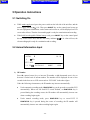
Go To Table Of Contents Back First Row: ♦ Operation mode (AUTO1, AUTO2, AUTO3 and MANU) ♦ II stop symbol, which will turn to ♦ Warning message (LD OFF, or PAPER? etc.) ♦ Current time while recording Second Row: ♦ Current lead (І, П, Ш, AVR, AVL, AVF, V) ♦ Heart rate (--, actual heart rate, or OVR message) Third Row: ♦ Filter setting (FLT = AC, ALL, OFF, EMG) ♦ ECG Fourth Row: ♦ Sensitivity (×1, ×2, AGC, · 25, · 5) ♦ Paper speed (25, 50) ♦ Battery capacity symbol ( ♦ Display the ID, sex (Male/Female) and age group (YOUNG/MATURE/OLD) while , , , ) setting; and “BATTERY WEAK” will be shown here when the battery capacity is weak. -13- Next Go To Table Of Contents Back 3.1.2 Control Panel and Keys 1) Indicator Mains supply indicator: when mains supply is used, the indicator will be lit. Battery indicator: when the built-in rechargeable lithium battery is used, the indicator will be lit. Battery recharging indicator: both the battery recharging indicator and mains supply indicator will be lit after the mains power switch has been turned on. After ON/OFF key being pressed, the battery recharging indicator will be black if the battery capacity is full. However, if the battery capacity is not full, the battery recharging indicator will be lit until the battery is full recharged, and after that the battery recharging indicator will be black. 2) SENS (Sensitivity Switch Key) The sensitivity switching order: ×1 → ×2 → AGC → · 25 → · 5 -14- Next Go To Table Of Contents Back Next The ECG signal range which can be measured and recorded is different according to different sensitivity, as the following list shows. Options Sensitivity Signal range measured ×1 10mm/mV -2.5mV ~ +2.5mV ×2 20mm/mV -1.25mV ~ +1.25mV AGC Auto Gain Control Adjust sensitivity automatically · 25 2.5mm/mV -10mV ~ +10mV ·5 5mm/mV -5mV ~ +5mV If the fluctuating range of the ECG signal is great, ‘AGC’ should be chosen since the sensitivity will be adjusted automatically under this mode. 3) RESET (Lead Locking Key) Press this key to lock the lead while ECG recording. After that, the corresponding ECG will be a line. It is always used to draw the baseline to zero quickly in the case of baseline excursion in actual ECG recording. The lead will be unlocked automatically after 0.4 seconds. 4) 1mV Calibration Key Under manual mode, this key can be pressed to record a 1mV calibration pulse at any time while recording. 5) MODE (Mode Switch Key) There are three automatic modes and a manual mode. This key can be pressed to select recording mode. The switching order of leads in each mode is listed in Table 3-1. -15- Go To Table Of Contents Back Next Table 3-1 Lead Switching order of Different Modes Mode Switching Order (from left to right) MANU І П Ш AVR AVL AVF V AUTO1 І П Ш AVR AVL AVF V AUTO2 AVL І AVR П AVF Ш V AUTO3 2 channel automatic mode (AUTO1 + Rhythm Lead) 6) LEAD (Lead Switch Key) Under manual mode, press the key to switch the lead order. 7) PRINT/STOP Key Used to begin recording and stop recording. 8) ON/OFF Key When the unit has been powered on, press this key to turn on or turn off the electrocardiograph. 9) MENU Key Press MENU key to enter menu settings interface. -16- Go To Table Of Contents Back 10) ID Setting Key These two ID keys can be pressed to set the animal’s ID number. Press the upward arrow key to increase ID number and press the downward arrow key to decrease ID number on the basis of current ID number. 11) M/F Press M/F key to choose sex, male (M) or female (F). 12) AGE Press AGE key to choose age: YOUNG, MATURE or OLD. 3.2 Patient Cable Socket and Signal Interface There are sockets including the patient cable socket, RS232 socket and external input/output socket at the right side of the main unit as the following Figure shows. Patient cable socket RS232 socket External Input/Output socket 1) Patient Cable Socket -17- Next Go To Table Of Contents Back Next : Defibrillation-proof applied part of type CF : Attention – see accompanying document Definition of corresponding pins: Signal Pin 1 NC 6 2 NC 3 Signal Pin Signal SH 11 F/LL (input) 7 NC 12 NC NC 8 NC 13 C /V(input) 4 NC 9 R /RA(input) 14 NC 5 NC 10 L /LA(input) 15 N or RF /RL(input) Note: The left side of “/” is European standard; and the right side is American standard. 2) RS232 Socket WARNING : RS232 interface is 1500V AC isolated intensity and the maximum voltage applied should not exceed +15V DC. Definition of corresponding pins: Pin Signal Pin Signal Pin Signal 1 NC 4 NC 7 NC 2 RxD (input) 5 GND 8 NC 3 TxD (output) 6 NC 9 NC -18- Go To Table Of Contents Back Next 3) External Input/Output Socket Definition of corresponding pins: Pin Signal Pin 1 GND 4 GND 2 GND 5 ECG Signal (input) 3 GND 6 ECG Signal (output) WARNING ♦ Signal : Accessory equipment connected to the interfaces must be certified according to the respective IEC standards (e.g. IEC60950 for data processing equipment and IEC 60601-1 for medical equipment). Furthermore all configurations shall comply with the valid version of the standard IEC 60601-1-1. Therefore anybody, who connects additional equipment to the input or output connector to configure a medical system, must make sure that it complies with the requirements of the valid version of the system standard IEC 60601-1-1. If in doubt, consult our technical service department or your local distributor. ♦ The summation of leakage current should never exceed leakage current limits while several other units are used at the same time. 3.3 Mains Connection and Switch Potential Equalization Conductor Mains Power Switch Mains Supply Socket At the left side of the main unit, there is the mains supply socket, power switch and potential -19- Go To Table Of Contents Back equalization conductor as the above figure shows. 1) Potential Equalization Conductor Potential equalization conductor provides a connection between the unit and the potential equalization bus bar of the electrical installation when necessary. 2) Mains Supply Socket AC SOURCE: alternating current supply socket 3) Power Switch : Switch on the mains power supply : Switch off the mains power supply -20- Next Go To Table Of Contents Back Next 3.4 Bottom Panel Mains Supply Shift Switch Fuse Fuse Battery Compartment Fuse Label Label 1) Battery Compartment The battery label indicates the rated voltage and rated capacity of rechargeable Lithium battery pack. Rated voltage: 14.4V, Rated capacity: 1600mAh. Attention – general warning (see accompanying document) WARNING :. The battery of same model and specification provided by manufacturer must be used. 2) Mains Supply Shift Switch Mains supply with rated input voltage 230V (220V~240V) or 115V (100V~115V) can be chosen by the shift switch according to local mains supply specification. -21- Go To Table Of Contents Back 3) Fuse There are two fuses installed on the bottom of the main unit. The specification is showed on the fuse label: AC220V-240V: T200mA; AC100V-115V: T400mA; Φ5×20. WARNING : Ruptured fuse must only be replaced with the same type and rating as the original. -22- Next Go To Table Of Contents Back Next 4 Operation Preparations CAUTION : Before use, the equipment, patient cable,electrodes and other accessories should be checked. Replace it if there is any evident defectiveness or aging which may impair the safety or performance. Be sure that the equipment is in proper working condition. 4.1 Power Supply WARNING : If the integrity of external protective conductor in installation or arrangement is in doubt, the equipment should be operated from the built-in rechargeable battery. The electrocardiograph can be powered either by mains supply or the built-in rechargeable lithium battery pack. 1) Mains supply The mains connection socket is on the left of the unit. If mains supply used, connect the power cord to the socket first, and then connect the plug of the cord to the hospital grade outlet. Rated input voltage: 100V~115V or 220V~240V Rated frequency: 50Hz/60Hz Rated input power: 35VA Make sure the mains supply meets the above requirements before powering on. And then press the mains power switch to power on the unit. Then the mains supply indicator ( ) will be lit as well as the battery recharging indicator ( ). If the built-in rechargeable battery is weak when mains supply used, the battery recharging indicator will be still lit after ON/OFF key pressed, which means the battery is being recharged. If the battery capacity is full, the recharging indicator will be black after ON/OFF key pressed. 2) Built-in rechargeable battery When the built-in rechargeable lithium battery pack is used, turn on the unit by pressing ON/OFF key on control panel directly and the battery indicator ( The battery symbol ) will be lit. will be displayed on the LCD screen. Because of the consumption during storage and transport, the capacity of battery may not be full. If the symbol -23- and Go To Table Of Contents Back Next the alarm information “BATTERY WEAK” are displayed, which means the battery capacity is weak, please recharge the battery first. Note: Please refer to the maintenance section for how to recharge the battery. During recharging the battery, the electrocardiograph can be powered by mains supply at the same time. WARNING : Potential equalization conductor of the unit should be connected to the potential equalization bus bar of the electrical installation when necessary. 4.2 Loading/Replacing Record Paper Rolled thermal paper with 50mm width is used as ECG record paper. When there is no record paper loaded or it reaches the end of record paper, warning message “PAPER?” will be given on the LCD screen. Under this circumstance, record paper should be loaded or replaced immediately. Casing Paper Roller Thermal Print Head Scale Roller Pin Printer Platen Groove Paper Tray Loading/Replacing Procedures: 1) Place fingers under the flange of the recorder casing, pull upwards directly to release the casing; 2) Take out the paper roller, and remove remaining paper from the left of roller if necessary; 3) Take off the wrapper of the new thermal paper roll, and then put through the roller from the left with the paper’s grid side facing downward. -24- Go To Table Of Contents Back 4) Next Then place the paper and roller gently in the paper tray with the roller pin on the roller’s left side facing to the groove; 5) Pull about 2cm of the paper out, and put down the recorder casing with the paper’s side edges in parallel with the scale on the surface of casing; 6) Secure the casing by pressing it firmly. 4.3 Patient Cable Connection Patient cable includes two parts, main cable and lead wires with associated electrode connectors. The electrode connectors can be distinguished by the color and identifier on them. Lead Wires Main Cable Electrode Connectors Connector Electrodes Connect Main Cable: Plug the connector of main cable into the patient cable socket on the right side of the unit, and secure the screw. WARNING ♦ : This product is CF classified and defibrillation protected only when the original patient cable is used. However, as a safety precaution when possible, remove electrodes before defibrillation. ♦ Precautions must be observed when using high frequency devices which may affect the quality of ECG. -25- Go To Table Of Contents Back Next 4.4 Electrodes Connections Clamp The identifier and color code of electrode connectors used complies with IEC requirements. In order to avoid incorrect connections, the electrode identifier and color code is specified in Table 4-1. Moreover, the equivalent code according to European requirements is given, too. Table 4-1 Electrodes, Identifier and Color Code European Electrodes Identifier American Color code Identifier Color code Right fore limb R Red RA White Left fore limb L Yellow LA Black Right rear limb N or RF Black RL Green Left rear limb F Green LL Red Chest C White V Brown As the following figure shows, the electrode areas on body surface are: European Standard Dog American Standard Cat Dog Cat The contacting resistance between the animal and the electrode will affect the quality of ECG greatly. In order to get a high-quality ECG, the skin/electrode resistance must be minimized while connecting electrodes. -26- Go To Table Of Contents Back Electrodes connection: 1) Ensure the electrodes are clean; 2) Align lead wires of patient cable to avoid twisting; 3) Clean electrode area with alcohol; 4) Daub the electrode area with gel evenly; 5) Place a small amount of gel on the metal part of electrode clamp; 6) Clamp the electrode to the electrode area. Attach all electrodes in the same way. WARNING ♦ : Be sure that all electrodes have been connected to the animal correctly before operation. ♦ Be sure that the conductive parts of electrodes and associated connectors, including neutral electrode, do not contact ground or any other conducting objects. ♦ There is no danger when using the electrocardiograph with electrical stimulation equipment. However, the stimulation units should only be used at a sufficient distance from the electrodes. If in doubt, the animal should be disconnected from the device. ♦ Electrodes with defibrillation protection should be used while defibrillating. ♦ Do not touch the unit casing during defibrillation. 4.5 Inspection before Switching on In order to avoid safety hazards and get good ECG records, the following inspection procedures are recommended before turning on the unit and beginning operation. 1) Environment: ♦ Check and make sure that there is no electromagnetic interference source around the equipment, especially large medical electrical equipment such as electrosurgical equipment, radiological equipment and magnetic resonance imaging equipment etc. Switch off these devices when necessary. ♦ Keep the examination room warm to avoid muscle action voltages in ECG signal caused by cold. 2) Power Supply: ♦ If mains power used, please check whether the power cord has been connected to the -27- Next Go To Table Of Contents Back unit well. The grounded three-phase outlet should be used. ♦ Recharge the battery first before use when the battery capacity is weak. 3) Patient Cable: ♦ Check whether the patient cable has been connected to the unit firmly, and keep it far away from the power cord. 4) Electrodes: ♦ Be sure that all electrodes have been connected to the animal correctly. ♦ Ensure that the electrodes haven’t contacted with each other. 5) Recorder Paper: ♦ Ensure that there is enough recorder paper loaded correctly. ♦ Make sure the recorder case has been secured. 6) Animal: ♦ The animal should not be in contact with conducting object such as ground, or metal table, etc. ♦ Ensure the animal is warm and relaxed, and breathing calmly. WARNING : The electrocardiograph is provided for the use of qualified veterinarians or personnel professionally trained. They should be familiar with the contents of this user manual before using. -28- Next Go To Table Of Contents Back Next 5 Operation Instructions 5.1 Switching On ♦ While mains supply used, press the power switch on the left side of the unit first, and the mains supply indicator ( ) is lit. Then press ON/OFF key on the control panel to turn on the unit. Equipment information, such as name and version etc, will be displayed on LCD screen after self-test. Then the electrocardiograph is ready for examination and recording. ♦ When built-in rechargeable lithium battery used, press ON/OFF key on the control panel directly to turn on the unit, and then the battery indicator ( ) is lit. After self-test, the electrocardiograph is ready for examination and recording. 5.2 Animal Information Input II AUTO 1 І 10 : 50 NO FLT = ALL ×1 25 1) ECG9803 MALE OLD ID Number Press ID (upward arrow) key to increase ID number or ID (downward arrow) key to decrease it on the basis of current number. The number will be displayed for one or two seconds in the last row on LCD screen such as ‘ECG 9803’ in the above figure. Under the following circumstances, the ID number may increase automatically: ♦ Under automatic recording mode, PRINT/STOP key can be pressed to record the ECG automatically. When one full lead ECG record finished, or PRINT/STOP key is pressed during the recording course, the ID number will automatically increase one when recording begins again. ♦ Under manual recording mode, press PRINT/STOP key to record ECG. If PRINT/STOP key is pressed during the course of recording, the ID number will automatically increase one when recording begins again. -29- Go To Table Of Contents Back 2) Next SEX Press M/F key to set the sex: female or male, which will be displayed for one or two seconds in the last row on LCD screen. 3) AGE Animals are divided into three groups based on age: YOUNG, MATURE, OLD. Press AGE key to set the age group, which will be displayed for one or two seconds in the right lower corner of LCD screen. Note: The animal information mentioned above cannot be set or changed during the course of recording. 5.3 Menu Settings 19 items in the menu are listed in Table 5-1. In the Options column, the value double underlined is the default settings. Table 5-1 Menu Items No. Menu Items Options 1 FILTER SETTING AC, ALL, OFF, EMG 2 PWAVE START ON, OFF 3 RECORD LENGTH 2, 3, 4, …, 11, 12 4 RECORD COUNT SECOND, QRS 5 RECORD SPEED 25, 50 (unit: mm/s) 6 HEARTRATE PRINT ON, OFF 7 YEAR 0~99 8 MONTH 1~12 9 DAY 1~31 10 HOUR 0~23 11 MINUTE 0~59 12 PRINT HEAD TEST ON, OFF 13 DEFAULT SETTING OFF, RESTORE 14 EXTINPUT RECORD ON, OFF 15 KEY BEEP ON, OFF -30- Go To Table Of Contents Back 16 QRS BEEP ON, OFF 17 RHYTHM LEAD І, П, Ш, AVR, AVL, AVF, V 18 LOWPASS FILTER OFF, 75HZ, 100HZ, 150HZ 19 LANGUAGE ENG, CHN Next Setting Method: 1) Press MENU key to enter menu settings displayed as the following figure; FILTER SETTING : ALL PWAVE START : ON RECORD LENGTH :3 RECORD COUNT : SECOND 2) Press ID key (upward or downward) to move the arrow at the right of LCD screen to the item to be changed. Take ‘FILTER SETTING’ as an example. The arrow stop at the item of FILTER SETTING. 3) Then press M/F key or AGE key to choose the setting options (EMG, AC, ALL, OFF); 4) Repeat 2) and 3) to set other items in the same way; 5) After modifying the items which need to be changed, press MENU key again to quit the menu interface with new settings. Note: Set the DEFAULT SETTING as RESTORE, and then the defaults of all items will be reloaded except date, time and language. Descriptions of some items and their settings are given in the following sections. 5.3.1 Filter Settings The filter can be chosen among EMG, AC, ALL (both of EMG and AC) or OFF (no filter). When choose OFF, the filter will not work. Generally, ALL is recommended to be set in order to get better ECG record. 5.3.2 Recording Settings Recording settings includes start, length, count unit, speed and contents. Such as: PWAVE START : ON -31- Go To Table Of Contents Back RECORD LENGTH :3 RECORD COUNT : SECOND RECORD SPEED : 25 HEART RATE PRINT : ON Take the above settings as example, the ECG will be recorded from P wave, and the printing speed is 25mm/s. The record length of each lead is 3 seconds. And the heart rate will be printed out at the bottom of the beginning of each lead recording. When QRS is taken as recording count unit, the record length will be 3 periods of QRS wave. Note: The record duration of each lead must be longer than 2 seconds. So when QRS is chosen to be the count unit, no matter how long the record length is, if the period of QRS wave is too short, the electrocardiograph will keep recording for 2 seconds. 5.3.3 Date and Time Settings The date and time on LCD screen and ECG record can be set in the following items: YEAR :7 MONTH : 12 DAY : 17 HOUR : 14 MINUTE : 25 Per the above settings, the date & time is Dec. 17th, 2007, 14:25 PM. And it will be printed out as 2007-12-17-14:25 on the record. 5.3.4 Print Head Test PRINT HEAD TEST: OFF Print head test is used to check whether the print head can work normally or not. The default status of print head test is OFF. Turn on this item when the print paper has been loaded. Then the triangle wave in effective paper width will be printed out. The status of print head can be estimated from this triangle wave. 5.3.5 External Input/Output Settings External input/output signal interface is equipped in the electrocardiograph, through which ECG signal from external equipment can be received, and ECG signal detected by the -32- Next Go To Table Of Contents Back electrocardiograph can be transmitted to other external equipment. Set the EXTINPUT RECORD as ON to turn on the function and OFF to turn off. 5.3.6 Key and QRS Beep Settings KEY BEEP : ON QRS BEEP : OFF When KEY BEEP is ON, a short beep sound will be heard when press the control key. When KEY BEEP is OFF, there is no sound while pressing the key. When QRS BEEP is ON, the unit will make a short beep sound when an R wave has been detected. 5.3.7 Rhythm Lead Settings RHYTHM LEAD: П Under AUTO 3 mode, ECG of one channel and a rhythm channel lead can be recorded. The rhythm lead can be any one of 7 standard leads: І, П, Ш, AVR, AVL, AVF and V. 5.4 Sensitivity Switching There are five options of sensitivity: ×1 (10mm/mV) → ×2 (20mm/mV) → AGC → · 25 (2.5mm/mV) → · 5 (5mm/mV) key to choose the appropriate sensitivity to achieve better ECG record according Press to the signal range that can be measured. Refer to Section 3.1.2 for details about signal range under different sensitivity. This key can be pressed during the course of examination or recording under manual mode while it is ineffective during the course of recording under automatic mode. 5.5 Automatic Mode Operation Three automatic recording modes are provided by this electrocardiograph, AUTO 1, AUTO 2 and AUTO 3. Two channels, including a rhythm lead, can be recorded together under AUTO 3 mode. The lead switching orders under different modes are listed in Table 3-1 in Section 3.1.2. -33- Next Go To Table Of Contents Back Next Under automatic mode, leads will be switched in order automatically while recording ECG. That means when ECG signal from one lead has been recorded for the set length such as 3 seconds, it will be switched to the next lead and begin recording another ECG signal. There is a pause for several seconds before recording the next ECG signal under the modes of AUTO1 and AUTO2. Moreover, a 1mV calibration pulse will be printed on the record automatically before ECG of each lead. Operation Procedures: 1) Press MODE key to choose automatic mode, which will be displayed in the left top corner on LCD screen; 2) If AUTO3 has been chosen, rhythm lead can be selected by pressing MENU key to set RHYTHM LEAD. The rhythm lead can also be set before selecting mode. Moreover there is no pause between different leads while recording. 3) Then press PRINT/STOP key to begin recording. The symbol means ECG is being recorded now. It will stop automatically after a full 7-lead ECG prints out. Pressing PRINT/STOP again during the course of recording can stop printing. However, when beginning recording later, ECG will be recorded in order from the first lead again. And ID number will increase one automatically. If the ID number does not need to be changed, ID key should be pressed to adjust it before recording. Note: Recording mode cannot be changed during the course of printing. Stop recording before choosing another recording mode. 5.6 Manual Mode Under manual mode, users can determine the lead to be recorded and set the recording settings or other parameters according to different leads. Operation Procedures: 1) Press MODE key to choose MANU mode, which can be discerned by the identifier on the left corner of LCD screen as MANU; 2) Press LEAD key (left arrow or right arrow key) to select the lead to be recorded; -34- Go To Table Of Contents Back 3) Press MENU key to set the record settings or other settings. After setting, press MENU key again to confirm the settings; 4) Then press PRINT/STOP key to begin recording; 5) 1mV calibration key can be pressed to print out 1mV pulse wave in the record while ECG recording; 6) Press PRINT/STOP key to stop printing after finishing ECG record. Note: LEAD left and right arrow key can be pressed to switch the lead during the course of recording. 5.7 ECG Record As the above figure shows, the ECG record includes: date and time, ID number, owner (written by doctor), name (written by doctor), type (written by doctor), weight (written by doctor), sex, age, sensitivity, paper speed, filter settings, lead name, 1mV calibration pulse, ECG, heart rate, and model of the equipment. At the beginning of each lead’s ECG, lead name and 1mV calibration pulse is printed. On the top of the ECG record of each lead, sensitivity is marked. The sensitivity may be different, for it can be changed during the course of recording. 5.8 Switch Off When built-in battery pack used, press ON/OFF key directly to turn off the unit after finishing ECG record. When mains supply used, press ON/OFF key first after finishing ECG record and then switch off the mains supply by pressing the switch on the left side of the unit. Un plug from the outlet last. -35- Next Go To Table Of Contents Back 6 Alarm Information Alarm information will be displayed on the LCD screen when there is something wrong. Alarm information provided by the electrocardiograph and corresponding cause is listed in Table 6-1. Table 6-1 Alarm Information and Causes Alarm Information Causes LD OFF Electrodes fall off from the animal or the patient cable falls off from the unit. PAPER? Record paper has not been loaded or it has been used out. BATTERY WEAK The built-in battery is weak. -- The heart rate is over 300BPM or below 30BPM, or heart rate has not been detected in 2 seconds. OVR The ECG signal exceeds the measuring range under certain sensitivity. -36- Next Go To Table Of Contents Back Next 7 Technical Specifications 1) IEC60601-1 Safety Standards 2) IEC60601-2-25 3) EN 60601-1-2 Anti-electric-shock type: Class І with internal power supply Anti-electric-shock degree: Type CF with defibrillation proof Degree of protection harmful ingress of water: Classification Ordinary equipment (Sealed equipment without liquid proof) Disinfection/sterilization method: Refer to the user manual for details Degree of safety of application in the presence of flammable gas: Equipment not suitable for use in the presence of flammable gas Working mode: Continuous operation EMC: Group І, type A Dimensions 300mm×260mm×75mm Weight About 2.3kg Display 192 × 64 pixels color LCD Transport Storage Working -20℃~50℃ -10℃~40℃ 5℃~40℃ Relative 25%~95% 25%~95% 25%~85% Humidity No Condensation No Condensation No Condensation 700hPa ~1060hPa 700hPa ~1060hPa 860hPa ~1060hPa Temperature Environment against Atmospheric Pressure Rated input voltage =100V~115V/220V~240V Mains Supply Rated frequency = 50/60Hz Rated input power = 35VA Power Supply Built-in Lithium Battery Rated voltage = 14.4V Pack Rated capacity = 1600mAh -37- Go To Table Of Contents Back Charge mode: Constant current/voltage Charge current (standard) = 0.2C5A (320mA) Charge voltage (standard) = (16.8±0.1V) Cycle life ≥ 300 times Power Consumption 35VA Fuse T200mA Ø5×20 or T400mA Ø5×20 Recorder Thermal dot-matrix printer Dot structure: 384 dots/line Thermal Print Head Dot pitch: 0.125mm (8 dots/mm) Dot size: 0.125mm×0.12mm Recording HR Recognition Record Paper Rolled thermal paper Paper Width 50mm Effective Width 48mm Paper Speed 25mm/s, 50mm/s Accuracy ±3% Technique Peak-peak detection HR Range 30BMP~300BMP Accuracy ±1BMP -38- Next Go To Table Of Contents Back Leads: 7 standard leads Acquisition Mode: One lead A/D Resolution: 12 digit Time Constant: ≥3.2s Frequency Response: 0.05Hz ~ 150Hz Sensitivity: 2.5, 5, 10, 20 (mm/mV) Input ImpMidmarkce: ≥10M Ω Input Circuit Current: ≤50nA Input Voltage Range <±5 mVpp Calibration Voltage: 1mV±3% Noise: <15 μ Vp-p ECG Unit Filter CMRR EMG Filter: 35Hz (-3dB) AC/DFT Filter: 50Hz/60Hz (-20dB) >90dB; >100dB (with AC filter) Patient Leakage Current: <10 μ A (220V~240V) Patient Auxiliary Current: <0.1 μ A (DC) Dielectric Strength: 4000V rms External Input/Output (Optional) Communication Interface Input (Single ended) ≥100k Ω ; Sensitivity10mm/V±5%; Output (Single ended) ≤100 Ω ; Sensitivity1V/mV±5%; RS232 (Refer to Section 3.2 for details) -39- Next Go To Table Of Contents Back 8 Cleaning, Care and Maintenance 8.1 Cleaning CAUTION : Turn off the power before cleaning and disinfection. If mains supply used, the unit should be switched off first and the power cord should be unplugged from the outlet. 8.1.1 Cleaning the Main Unit and Patient Cable The surface of the main unit and patient cable can be wiped with a clean soft cloth damped in soapy water or non-caustic neutral detergent. After that, remove detergent remainder with a clean dry cloth. 8.1.2 Cleaning the Electrodes Remove the remainder gel from the electrodes with a clean soft cloth first. Clean them in warm water and be sure there is no remainder gel. Dry the electrodes with a clean dry cloth or air dry naturally. 8.1.3 Cleaning the Print Head Dirty and soiled thermal print head will deteriorate the record definition. So it should be cleaned at least once a month regularly. Open the recorder casing and remove the record paper. Wipe the print head and printer platen gently with a clean soft cloth damped in 75% alcohol. For stubborn stain, soak it with a little alcohol first and wipe it off with a clean soft cloth. After air drying, load the record paper and shut the casing of the recorder. CAUTION ♦ : Prevent the detergent from seeping into the main unit while cleaning. Do not immerse the unit or patient cable into liquid under any circumstances. ♦ Do not clean the unit and accessories with abrasive fabric and avoid scratching the electrodes and thermal print head. -40- Next Go To Table Of Contents Back 8.2 Disinfection To avoid permanent damage to the equipment, disinfection can be performed only when it has been considered as necessary according to your hospital’s regulations. Before disinfection clean the equipment first. Then wipe the surface of the unit and patient cable with 70% isopropyl alcohol. Wipe the surface of electrodes with 70% alcohol or isopropyl alcohol. Never immerse the unit, cable or electrodes into disinfectant solution. CAUTION : Do not use chloric disinfectant such as chloride and sodium hypochlorite, etc. 8.3 Care and Maintenance 8.3.1 Recharge and Replacement of Battery 1) Capacity Identification Current capacity of the rechargeable battery can be identified according to the battery symbol in the last row on LCD screen. : Full capacity : Not full but enough : Capacity is limited, and recharge should be taken into account : Battery is weak; and warning message “BATTERY WEAK” will be displayed on LCD screen. The battery should be recharged immediately 2) Recharge The electrocardiograph is equipped with recharge control circuit together with built-in rechargeable lithium battery. Once the main unit is connected to mains supply with power cord, the battery will be recharged automatically. And then the battery recharge indicator ( ) and the mains supply indicator ( ) will be lit at the same time. When the capacity of battery is full, the battery recharge indicator ( ) will be black. Because of the capacity consumption during storage and transport, the capacity of battery is not full while being used at the first time. Battery recharge is recommended before first usage. -41- Next Go To Table Of Contents Back 3) Replacement When the useful life of battery is over, or foul smell and leakage has been found, please contact with manufacturer or local distributor for replacement of battery. WARNING ♦ : Only qualified service engineer authorized by Midmark can open the battery compartment and replace the battery. The battery of same model and specification provided by manufacturer must be used. ♦ Danger of explosion -- Do not reverse the anode and cathode when connecting the battery. ♦ When the battery’s useful life is over, contact the manufacturer or local distributor for disposal or dispose the battery according to local regulations. 8.3.2 Record Paper Storage requirements: ♦ Record paper should be stored in dry, dark and cool area, avoiding excessive temperature, humidity and sunshine. ♦ Do not put the paper under fluorescence for long time. ♦ Be sure that there is no polyvinyl chloride or other chemicals in the storage environment, which will lead to color change of the paper. ♦ Do not overlap the recorded paper for a long period, or else the ECG record may trans-print each other. ♦ Note: Recording paper provided by manufacturer should be used. Other paper may shorten thermal print head’s life. And the deteriorated print head may lead to illegible ECG record and block the advance of paper etc. -42- Next Go To Table Of Contents Back 8.3.3 Maintenance of Main Unit, Patient Cable & Electrodes The following safety checks should be performed at least every 24 months by a qualified person who has adequate training, knowledge, and practical experience to perform these tests. a) Inspect the equipment and accessories for mechanical and functional damage. b) Inspect the safety relevant labels for legibility. c) Inspect the fuse to verify compliance with rated current and breaking characteristics. d) Verify the device functions properly as described in the instructions for use. e) Test the protection ground resistance according to IEC 601-1/1988: Limit 0.2ohm. f) Test the ground leakage current according to IEC 601-1/1988: Limit: NC 500uA, SFC 1000uA. g) Test the patient leakage current according to IEC 601-1/1988: Limit: 10uA (CF). h) Test the patient leakage current under single fault condition with mains voltage on the applied part according to IEC 601-1/1988: Limit: 50uA (CF). The leakage current should never exceed the limit. The data should be recorded in an equipment log. If the device is not functioning properly or fails any of the above tests, the device has to be repaired. WARNING : Failure on the part of the responsible individual hospital or institution employing the use of this equipment to implement a satisfactory maintenance schedule may cause undue equipment failure and possible health hazards. 1) Main Unit ♦ Avoid excessive temperature, sunshine, humidity and dirt. ♦ Put on the dustproof coat after use and prevent from shaking violently when moving it to another place. ♦ Prevent any liquid from seeping into the equipment, for it will affect the safety and performance of the electrocardiograph. 2) Patient Cable ♦ Integrity of patient cable, including main cable and lead wires, should be checked regularly. Be sure that it is conductible. ♦ Do not drag or twist patient cable with excessive stress while using. Hold the connector plugs instead of the cable when connecting or disconnecting the patient cable. -43- Next Go To Table Of Contents Back ♦ Align the patient cable to avoid twisting, knotting or crooking in closed angle while using. ♦ Store the lead wires in bigger wheel. ♦ Once damage or aging of the patient cable has been found, replace it with a new one immediately. 3) Electrodes ♦ Electrodes must be cleansed after use and be sure there is no remainder gel on them. ♦ After long-term use, the surface of electrodes will be oxidized because of erosion and other causes. By this time, electrodes should be replaced to achieve high-quality ECG. CAUTION : The equipment and reusable accessories can be sent back to the manufacturer for recycling or proper disposal after their useful lives. -44- Next Go To Table Of Contents Back 9 Service Warranty Material and Manufacture The warranty period for the main unit and the accessories is 24 months from the date of shipment. Midmark warrants that there’s no defect in material and manufacture. During the warranty period, Midmark will repair or replace the defective part free if the defect has been confirmed as material or manufacture defect. Software or Firmware For the software or firmware installed, Midmark will replace the software or firmware free if the defect has been confirmed during 24 months from the date of shipment. But Midmark cannot warrant it will not interrupt the use of the product. CAUTION : All services must be done by the engineers authorized by Midmark. Limit of Warranty The charges of freight and others are excluded under warranty. The warranty is void in the case of ♦ Assembly, extensions, readjustments of any parts; ♦ Modification and repair by unauthorized persons; ♦ Subsequent damage caused by improper use or maintenance; ♦ Replacement or remove of the label of serial number and manufacturer. -45- Next Go To Table Of Contents Back 10 Accessories and Ordering Information The accompanying accessories of the electrocardiograph are listed in Table 10-1. Table 10-1 Accessories List No. 1 Accessory Manufacturer / Part No. Power cord M13R-36014 MS1R-109826-A0 2 (European standard) Patient cable MS1R-109827-A0 (American standard) 3 Alligator clip electrode M15R-040144 4 Paper roller MS1-19992 5 Thermal paper MS1R-19917 The following accessories can also be ordered according to some special usage. No. Accessory Manufacturer / Part No. 1 Grounding wire MS1-20016 2 Input/output signal cable MS1-19907 3 Flat clip electrode M15R-040145 4 Carrying Bag MS1-107119-A0 The main unit and accessories are available by contacting Midmark. -46- Next Back Go To Table Of Contents 10008 N. Dale Mabry Hwy, Suite 110, Tampa, FL 33618 TEL: 800-643-6275 FAX: 813-264-6218 www.Midmark.com