1
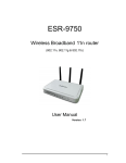
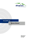
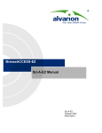
SU-I CPE Quick Installation Guide
This Quick Installation Guide, to be used during the trial phase, is intended for experienced installers. A simplified Installation Guide
for the non-professional end user will be available with the final product.
For more detailed information on this unit and its installation, configuration and commissioning, refer to the relevant sections in the
System Manual and the Configuration Utility User Manual. For more details on mounting the antenna (SU-I-D units) refer to the
mounting instructions supplied with the antenna.
NOTE: It is recommended to fully configure the unit prior to shipment to the client to enable “plug and play”
installation with no configuration.
SU-I CPE Package Content
Check that the package contains:
•
SU-I CPE
•
Power Adapter (with mains North America power plug terminator and EU power plug adapter)
•
3 meters Ethernet Cable (crossed, for connecting directly to a PC’s Network Interface Card)
•
Only with SU-I-D: Wall/window mountable detached antenna kit, including wall/window mounting accessories and a 2 meters
SMA-SMA (M/M) RF cable.
•
This Quick Installation Guide.
Additional (Optional) Equipment and Tools Required for Installation
•
•
•
•
Mains plug adapter or termination plug (if the North American power plug on the power adapter or the EU power plug adapter
supplied with it do not fit local power outlets).
A straight Ethernet cable if the user’s data equipment is a hub/switch/router.
A portable PC with an Ethernet card for configuring parameters using either Telnet or the Configuration Utility. TFTP server SW
is required for downloading SW versions.
Other installation tools and materials (drill for wall mounting the antenna if applicable, means for securing cables to walls, etc.).
Equipment Location Guidelines
The unit can be placed on a desktop or a shelf. It can also be wall mounted using the optional bracket. The SU-I uses a detached
antenna that can be either wall- or window-mounted. Select the optimal locations for the equipment using the following guidelines:
1. It is recommended to install the antenna on a wall outside the building, to avoid the significant attenuation caused in indoor
installations by glass windows or other obstacles. The antenna should be facing the direction of the Base Station (clear line of
site up to 300 meters from the BST). Use only the RF cable supplied with the antenna (if needed, use a longer Ethernet cable
to connect the SU-I to the PC).
CAUTION: In order to avoid damage from lightening, the antenna must be placed below roof level. Do not
connect or disconnect the antenna during a lightening storm.
2.
In indoor installations (not recommended), avoid metal obstacles such as metal window frames or metal film anti-glare windows
in the transmission path. Position the antenna away from electrical equipment, including the data equipment, monitor etc.,
metal furniture, and moving metal objects such as metal fans or doors.
Connecting the SU-I CPE
1.
2.
3.
4.
5.
6.
7.
Connect the Power Adapter DC cable to the POWER jack. Connect the Power Adapter to the AC mains.
Verify that the green Status LED located on the unit's front panel illuminates, indicating that the power supply to the unit is OK
and self test passed successfully.
Connect the RF cable supplied with the antenna to the SMA jack located on the unit’s front panel. Install the antenna using the
instructions provided below, and connect to it the other end of the RF cable. Do not overtighten the SMA connectors.
If parameters are not pre-configured, configure the basic parameters as described below.
Align the antenna as described below.
Connect the 10/100 Base-T Ethernet connector to the data equipment. Use a crossed cable (supplied with the unit) to connect
to a PC. Use a straight cable to connect to a hub/switch/router.
Verify proper operation of the Ethernet link The Ethernet Activity green LED should be on and the Ethernet Integrity
yellow LED should blink when there is Ethernet traffic. To verify data connectivity from the end-user's PC
or from a portable PC connected to the unit, ping a known device in the network, or try connecting to the
Internet.
Wall Mounting the Detached Antenna (simple mounting, without rotation capability)
1.
2.
3.
If anchors are needed (wall-board, plaster board, etc.), drill two holes for the anchors using a 5 mm drill bit
and insert anchors. Use a 9/64" drill bit for screwing directly into a solid surface (stud).
Fasten the antenna to the wall. Use the two #8 screws provided with the kit. Do not overtighten.
Connect the antenna cable to the connector located on the bottom side of the antenna. Hand tighten, do not
use a wrench or a similar tightening tool. Do not overtighten.
1
P/N: 214593
June 2007
SU-I CPE Quick Installation Guide
Wall Mounting the Detached Antenna with Rotation Capability
1.
2.
3.
4.
5.
6.
7.
If anchors are needed (wall-board, plaster board, etc.), drill two holes (361 mm apart) for the
anchors using a 5 mm drill bit and insert anchors. Use a 9/64" drill bit for screwing directly
into a solid surface (stud).
Assemble the top L-type plate with the Wall-V L-type plate. Note, the Wall-V plate is the one
with the vertical ellipse on the short side. Make sure the inscriptions are facing upwards. Use
two M5 screws to fasten the plates together. Do not overtighten.
Assemble the bottom L-type plate with the Wall-H L-type plate. Note, the Wall-H plate is the
one with the horizontal ellipse on the short side. Make sure the inscriptions are facing
upwards. Use two M5 screws to fasten the plates together. Do not overtighten.
Attach the assembled plates to the flat rear-side of the antenna. Use the two remaining M5
screws to fasten them.
Fasten the antenna to the wall. Use the two #8 screws provided with the kit. Do not
overtighten.
Connect the antenna cable to the connector located on the bottom side of the antenna. Use
only the torque key supplied with the antenna. Do not overtighten. Do not use a wrench or a
similar tightening tool.
Rotate the antenna left or right so the domed surface of the antenna is facing the direction of
the Base Station. Check the received Signal LEDs to ensure the antenna is aimed correctly.
Window Mounting the Detached Antenna (simple mounting, without rotation
capability)
1.
2.
3.
Attach the suction cups to the antenna.
Determine the location of the antenna on the glass. Attach it to the window by pressing the suction cups
onto the glass.
Connect the antenna cable to the connector located on the bottom side of the antenna. Use only the
torque key supplied with the antenna. Do not overtighten. Do not use a wrench or a similar tightening tool.
NOTE: The suction cups are sensitive to weather conditions and may not hold in high
temperatures or during rain. It is strongly recommended to mount the antenna on the wall using
supplied brackets.
the
Window Mounting the Detached Antenna with Rotation Capability
1.
2.
3.
4.
Attach the rotation bars to the antenna and the suction cups to the rotation bars.
Determine the location of the antenna on the glass. Attach it to the window by pressing the
suction cups onto the glass.
Connect the antenna cable to the connector located on the bottom side of the antenna. Use only the
torque key supplied with the antenna. Do not overtighten. Do not use a wrench or a similar tightening
tool.
Rotate the antenna left or right so the domed surface of the antenna is facing the direction of the Base
Station. Check the received Signal LEDs to ensure the antenna is aimed correctly (see Table 4).
NOTE: The suction cups are sensitive to weather conditions and may not hold in high
temperatures or during rain. It is strongly recommended to mount the antenna on the wall
using the supplied brackets.
Basic Configuration
NOTE: It is recommended to fully configure the unit prior to shipment to the client to enable “plug and play” installation without
configuration. If the unit is fully pre-configured, you can skip this section.
Unit’s configuration can be performed using either Telnet or the configuration utility.
1. Connect a PC to the Ethernet port, using a crossed cable. The default SU’s IP address is 10.0.0.1. If you use the configuration
utility, you can use the Set IP feature to set the SU’s IP address based on its MAC address. (Refer to the Configuration Utility
User Manual).
2. If you use Telnet for initial configuration, run the Telnet program. Select your permitted Access Level and enter your Password.
Access the Basic Configuration menu and configure the basic parameters required to allow connectivity with the Base Station
2
P/N: 214593
June 2007
SU-I CPE Quick Installation Guide
and to support remote management of the unit. In many installations, most of these parameters should not be changed from
their default values. The following list includes the basic parameters and their default values:
Table 1: Basic Parameters
Parameter
Default Value
Ethernet Port Negotiation Mode
(in Unit Control Parameters)
IP Address
Subnet Mask
Default Gateway Address
DHCP Options
Access to DHCP
ESSID
User Defined Frequency Subsets
Transmit Power
Auto Negotiation
10.0.0.1
255.0.0.0
0.0.0.0
Disable
From Wireless Only
ESSID1
A (All)
Depends on Sub Band
Maximum Tx Power
Depends on Sub Band
ATPC Option
Antenna Gain
Enable
According to the antenna
supplied with the unit and the
Sub Band.
Best AU Support
Preferred AU MAC Address
Disable
00-00-00-00-00-00 (none)
Maximum Modulation Level
8 (or the highest value supported
according to the country code).
65535
Open System
Disable
WEP
Key 1
00…0 (32 zeros = no key)
VLAN ID-Management
Authentication Algorithm
Data Encryption Option
Security Mode
Default Key
Key 1 to Key 4
3.
Comment
Tx Power cannot be higher than the
Maximum Tx Power parameter.
Max Tx Power cannot be higher than the
upper limit defined in the Sub Band in use.
If set to “Not Set Yet”, must be configured
according to actual value, taking into account
cable’s attenuation. For the antenna supplied
with SU-I-D, the net gain is 11.5 dBi.
Applicable only when Best AU Support is
enabled
Refer to Configuring the Maximum
Modulation Level in the next page.
Availability of security parameters depends
on support according to the country code.
Reset the unit to apply the changes.
Aligning the Antenna
1.
2.
3.
4.
5.
Point the antenna towards the general direction of the Base Station.
Verify that the power indication of the unit is on.
Verify that the green Status LED illuminates and at least one LED of the Signal LEDs is on, indicating that the unit is
synchronized with the Base Station. If the SU is not synchronized with the Base Station (indicated by the red signal LED),
ensure that all parameters are configured properly. If the unit is still not synchronized with the Base Station, try improving the
quality of the link by changing the direction of the antenna or by placing the unit/antenna at a higher or alternate location.
Try changing the location/direction of the antenna until the maximum link quality reading is achieved (maximum signal LEDs
are illuminating). If you encounter prolonged difficulty in achieving the expected link quality, try improving the reception quality
by placing the unit/antenna at an alternate location.
Ensure that the front of the antenna is always facing the Base Station. However, in certain conditions, such as when the line of
sight to the Base Station is hampered, better reception may be achieved using a reflected signal. In this case, the antenna is
not necessarily directed towards the Base Station.
Configuring the Maximum Modulation Level
Check the SNR of the SU at the AU. You can use Telnet to view the SNR values in the MAC Address Database, which can be
accessed from the Site Survey menu. If the ATPC algorithm is not enabled in both AU and SU, the test should be done with the
Initial Power Level at the SU configured to its maximum value. If the SNR is lower than the values required for the maximum
modulation level according to the Recommended Maximum Modulation Level table below (Table 2), it should be changed. It is
recommended that a 2 dB margin be added to compensate for possible measurement inaccuracy or variance in the quality of the
link.
NOTE: The SNR measurement at the AU is accurate only when receiving transmissions from the applicable SU. Use the Ping Test
utility in the Site Survey menu to verify data transmission.
3
P/N: 214593
June 2007
SU-I CPE Quick Installation Guide
Table 2: Recommended Maximum Modulation Level
SNR
SNR> 23 dB
21 dB < SNR < 23 dB
16 dB< SNR < 21 dB
13 dB < SNR < 16 dB
10 dB < SNR < 13 dB
8 dB < SNR < 10 dB
7 dB < SNR < 8 dB
6 dB<SNR < 7 dB
Recommended Maximum Modulation Level
8
7
6
5
4
3
2
1
Verifying Proper Operation
1.
2.
Verify data connectivity by pinging the Access Unit or by connecting to the Internet.
To verify the correct operation of the SU-I unit, examine the LED indicators located on the front panel of the SU-I unit. Table 3
and Table 4 list the provided LEDs and their associated indications.
Table 3: LED Indication
Symbol/Name
Description
Status
Self-test and power
indication
Ethernet
Ethernet activity/
connectivity
indication
W-Link
Wireless Link traffic
Indication
Functionality
Green: Power is available and self-test passed.
Blinking Amber: Testing (not ready for operation)
Red: Self-test failed. Fatal error
Green: Ethernet link between the SU-I and the data equipment is
detected, no activity
Blinking Green: Ethernet connectivity is OK, with traffic on the port.
Blinking rate is proportional to traffic rate.
Red: No Ethernet connectivity between the SU-I and the data
equipment.
Green: Unit is associated with an AU, no wireless link activity
Blinking Green: Data received or transmitted on the wireless link.
Blinking rate is proportional to traffic rate.
Off: Wireless link disabled
Table 4: SNR Bar LEDs
SNR Bar LEDs
LED 1 (red) is On
LED 2 (green) is On
LEDs 2 to 3 (green) are On
LEDs 2 to 4 (green) are On
LEDs 2 to 5 (green) are On
LEDs 2 to 6 (green) are On
LEDs 2 to 7 (green) are On
LEDs 2 to 8 (green) are On
LEDs 2 to 9 (green) are On
LEDs 2 to 9 (green) and 10 (orange) are On
SNR (typical)
Signal is too low (SNR < 4 dB)
SNR > 4 dB
SNR > 8 dB
SNR > 13 dB
SNR > 19 dB
SNR > 26 dB
SNR > 31 dB
SNR > 38 dB
SNR > 44 dB
Signal is too high (SNR > 50 dB)
FCC Radio Frequency Interference Statement
This equipment has been tested and found to comply with the limits for a class B digital device, pursuant to ETSI EN 301 489-1
rules. These limits are designed to provide reasonable protection against harmful interference when the equipment is operated in a
residential environment notwithstanding use in commercial, business and industrial environments. This equipment generates, uses,
and can radiate radio frequency energy and, if not installed and used in accordance with the instruction manual, may cause harmful
interference to radio communications.
R&TTE Compliance Statement
This equipment complies with the appropriate essential requirements of Article 3 of the R&TTE Directive 1999/5/EC.
4
P/N: 214593
June 2007