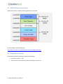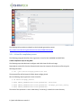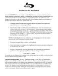
1
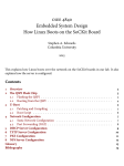
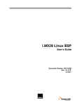
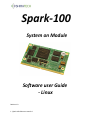
Spark-100 System on Module Software user Guide - Linux Revision 1.0 1 | Spark-100 SW user manual 1.0 1 Overview ............................................................................................................................................... 4 2 Linux SW overview ................................................................................................................................ 4 3 2.1 Linux overview ............................................................................................................................... 4 2.2 SD card/eMMC format and structure ............................................................................................ 5 2.3 QSPI Flash format and structure .................................................................................................... 6 2.4 Supported Linux version ................................................................................................................ 6 SW version creation and modification .................................................................................................. 7 3.1 Setting Cross Compilation Environment ........................................................................................ 7 3.2 Preloader and U-boot compilation steps ....................................................................................... 7 3.2.1 3.3 Kernel compilation procedure ....................................................................................................... 9 3.4 File system - compilation and installation.................................................................................... 10 3.4.1 File system for SD/eMMC ....................................................................................................... 10 3.4.2 File system for QSPI Flash memory ......................................................................................... 10 3.5 4 U-Boot file compilation process................................................................................................ 8 Cross Compiling C code ................................................................................................................ 10 SW installation .................................................................................................................................... 12 4.1 Preparing an SD card.................................................................................................................... 13 4.2 eMMC device SW download ........................................................................................................ 14 4.2.1 Via QSPI flash .......................................................................................................................... 14 4.2.2 Via SD card .............................................................................................................................. 15 4.3 QSPI flash SW download .............................................................................................................. 17 2 | Spark-100 SW user manual 1.0 Document Revision History Revision Date 1.0 3 | Spark-100 SW user manual 1.0 Description Initial version 1 Overview The software user guide includes 3 parts: Section 2 includes a description of the software files required for operating the Spark and their location in the memory. Section 3 describes how to compile the various parts of the software including a C code based application program and how to execute it on the SPARK board. Section 4 includes an explanation on how to download the SW to the Spark and how to perform software upgrade. 2 Linux SW overview 2.1 Linux overview Linux firmware required for operating the SPARK-100 consists of following parts: 1. Boot Program located within the ARM processor, it checks if a valid boot code is present in SD card or QSPI FLASH or other(the search is done based on the Bsel lines) and in case it find it, the bootstrap is downloaded it into RAM. 2. Preloader – The Preloader handles the basic hardware configuration. It is generated using the handoff information generated by the Quartus tool. 3. U-Boot - The boot, handles the for starting the kernel and can be used for downloading kernel and file system binaries from an external device or from the network. 4. Linux kernel – the operating system kernel. 5. Device tree - The Device Tree is a binary file containing the description of the SoC, its power and clock related information, the pin configuration details and the interfaces that are to be initialized along with their corresponding resources. 6. Root File-system - Contains basic user space initialization and applications which are executed on the target, using the OS kernel services. The Linux SW can be located in a QSPI flash, in an SD card or the internal eMMC device. The following sections will describe how the boot loader and u-boot can be downloaded to the board and then subsequently how the Linux kernel can be loaded onto memory using the different options. 4 | Spark-100 SW user manual 1.0 2.2 SD card/eMMC format and structure If an SD/eMMC device is used for software storage, it should be divided to three partitions: A dedicated raw partition (Type A2) for Boot, U-boot. A FAT partition for Kernel and device tree. o Note: For programming the FPGA by the U-boot the FPGA programing file should be located in the FAT partition as well along with the relevant scripts for downloading it to the FPGA. An EXT 3/4 partition for Linux file-system. Additional partitions can be used for backup and user data. The following link provides more details on how to create the required partitions: http://www.rocketboards.org/foswiki/Documentation/GSRD131SdCard. Note: The internal eMMC requires the same partitions as the SD card. 5 | Spark-100 SW user manual 1.0 2.3 QSPI Flash format and structure If QSPI flash memory is used the following partitions are required: For more details see the following link: http://www.rocketboards.org/foswiki/Documentation/GSRD131QspiBoot 2.4 Supported Linux version The version delivered by Shiratech is based on the following Linux Kernel version - 3.9.0 The fs version is Linux Linaro file system with Ubuntu version 13.0 6 | Spark-100 SW user manual 1.0 3 SW version creation and modification This section describes how to compile the various SW parts. 3.1 Setting Cross Compilation Environment Before starting with the Linux compilation steps it is required to setup the cross compiler environment on Linux host system. To install and setup the tool chain perform the following steps: $ wget https://launchpad.net/linaro-toolchainbinaries/trunk/2012.11/+download/gcc-linaro-arm-linux-gnueabihf-4.72012.11-20121123_linux.tar.bz2 $ tar xjf gcc-linaro-arm-linux-gnueabihf-4.7-2012.1120121123_linux.tar.bz2 $ export CROSS_COMPILE=~/gcc-linaro-arm-linux-gnueabihf-4.7-2012.1120121123_linux/bin/arm-linux-gnueabihfQuartus version 13.0 or newer is required along with Altera Embedded Design Suite 13.0 version or later (SOC EDS 13.0) as well for generating boot loader code for the Altera SOC based board. 3.2 Preloader and U-boot compilation steps The following paragraph describes the creation procedure for the following components: Preloader U-boot Altera provides “Preloader” generator tool called BSP editor which enables the generation of the initial boot code for the Altera SOC. This tool generates the boot code based on user configuration. The tool is part of the Altera SOC EDS tool. 1. Open the BSP-editor by entering the following command in the host system terminal: $ bsp-editor 2. The bsp editor GUI opens up 3. Selected the required option either BOOT_FROM_QSPI or BOOT_FROM_SDMMC. Press Generate Button and exit. 7 | Spark-100 SW user manual 1.0 The following link provides more details on the Preloader generation process: http://www.rocketboards.org/foswiki/Documentation/GSRD131Preloader 3.2.1 U-Boot file compilation process The following paragraph describes how to generate U-boot for both SD/eMMC and QSPI Flash. U-boot compilation steps for SD_CARD The following steps describe how to configure and build U-boot for SD-card usage: Download the sources file from the Shiratech web site and un-compress SD-card source files using the following command: $ tar -jxvf uboot-socfpga_sdcard.tar.bz2 The extracted files will be located in folder uboot-socfpga_sdcard Run the following steps to generate a new U-boot file $ cd uboot-socfpga_sdcard $ make CROSS_COMPILE=arm-linux-gnueabihf- distclean $ make CROSS_COMPILE=arm-linux-gnueabihf- socfpga_cyclone5_config $ make CROSS_COMPILE=arm-linux-gnueabihfThe result of this operation is a new U-Boot binary "u-boot.img" created in the same directory. 8 | Spark-100 SW user manual 1.0 U-boot compilation steps for QSPI version The following steps describe how to configure and build U-boot for QSPI version Download the sources file from the Shiratech site and un-compress the source files using the following commands: $ tar -jxvf uboot-socfpga_qspi_jul7_2014.tar.bz2 $ cd uboot-socfpga_qspi $ make CROSS_COMPILE=arm-linux-gnueabihf- distclean $ make CROSS_COMPILE=arm-linux-gnueabihf- socfpga_cyclone5_config $ make CROSS_COMPILE=arm-linux-gnueabihfThe result of this operation is a U-Boot binary "u-boot.img" created in the same directory. This image should be renamed to "u-boot_jffs2.bin" for flashing to QSPI using SDCARD U-Boot scripts, for more details see section 4.2. 3.3 Kernel compilation procedure For Configuring and generating the kernel files follow the following steps: Download the source files from the Shiratech site and un-compress the source files using the following commands: $ tar -jxvf linux-socfpga_July14_2014.tar.bz2 Configure and compile the kernel using the following commands $ cd linux-socfpga $ cp -vr config/socfpga_def_config .config $ make ARCH=arm CROSS_COMPILE=arm-linux-gnueabihf- LOADADDR=0x8000 These commands will create "zImage" in arch/arm/boot directory and "socfpga_cyclone.dtb" in "arch/arm/boot/dts" directory. For loading the files to the QSPI using the provided scripts socfpga_cyclone.dtb" should be renamed to "socfpga.dtb" , for flashing to QSPI Flash device, "zImage" should be renamed to "zImage_qspi", and "socfpga_cyclone5.dtb" to "socfpga_qspi.dtb" and place in the FAT part of the SD card, see section 4.2.3 for more details. 9 | Spark-100 SW user manual 1.0 3.4 File system - compilation and installation 3.4.1 File system for SD/eMMC The file system is available from the Shiratech web site as “rootfs.tar.gz” file. This file needs to be decompressed and copied to the ext3 partition of the SD card or to the eMMC device. User can also download light weight Linaro desktop file system into the eMMC or SD card for that link: http://www.rocketboards.org/foswiki/Projects/SoCKitLinaroLinuxDesktop 3.4.2 File system for QSPI Flash memory QSPI Flash has space constraints and hence only minimal file system can be used. For creating JFFS2 file system to be loaded in to the QSPI Flash the following steps should be followed: $ tar -jxvf rootfs_minimal_jul7_2014.tar.bz2 $ mkfs.jffs2 -r rootfs /home/dshiva/rootfs -e 65536 -s 1 -p -n -o rootfs.jffs2 This creates a rootfs.jffs2 file which needs to be copied with the other QSPI related images onto an SD card for flashing into the QSPI flash device on board. 3.5 Cross Compiling C code The following paragraph describes the steps required to cross compile a C source code application and execute it on the Spark: The tool chain to be used will be same as mentioned in the section 3.1. The path of the tool chain should be added to the host system environment as default path. Ex: export PATH=”$PATH:/usr/opt/arm-linux/arm-linux-gnueabihf-bin” Assuming that the sample program to be compiled is “source.c” then user can compile the code with the following command: $ arm-linux-gnueabihf- source.c -o source_output -static The result will be a binary named “source_output”. The binary needs to be downloaded to the target board using one of the following options: 1. Using network utilities like FTP 2. Using USB memory device For example, using tftp, the file can be transferred to the target file-system using, $ tftp -g -r source_output 10 | Spark-100 SW user manual 1.0 target_ip The execution permission to “source_output” should be ensured to the binary file using: $ chmod +x source_output With this the file can be executed on the target: $ ./source_output 11 | Spark-100 SW user manual 1.0 4 SW installation The Spark can run software from one of the following storage devices(see block diagram below): - An external SD card - An internal eMMC - QSPI NOR Flash memory. HPS QSPI D[0..3]. Ctrl QSPI 1Gb EEPROM Authentication I2C1 D[4..7] D[0..3], Ctrl MMC D[0..3], Ctrl eMMC 4-8GB SDIO MUX (TXS02612) Select D[0..3], Ctrl Module Carrier uSD Card Spark – 100 memory devices The selection of the storage to be used for boot is done using the BSEL pins. On the CB-50 the Bsel pins can be set using 3 jumpers: BSEL 0 – Select SDIO device, selects between SD (1-2) and eMMC (2-3) BSEL 1 – Selects boot source between QSPI NOR Flash (1-2) and SD/eMMC (2-3) BSEL 2 – Unused, should be set to (1-2) 12 | Spark-100 SW user manual 1.0 Section 4.1 describes how to make an SD card for the Spark. Optionally a disk image for 8GB SD card is also available from the Shiratech site. Using Win32 Disk Imager or similar tool an SD card can be produced. The following paragraphs describe how to download SW for each of these options. 4.1 Preparing an SD card The following procedure describes how to make a bootable SD card: For booting from an SD card, it should include three partitions. Let us assume that SD card is detected as /dev/sdx in the host system, in that case there should three partitions detected in the SD as sdx1(FAT partition), sdx2(ext3), sdx3(RAW). For Partitioning the SDCARD use a disk utility to create of a 21MB FAT partition (can be larger) and a Ext3 partition which leaves at least 1MB free to use for the RAW partition (A2). These partitions should include the following files in each partition (Assuming the device associated with SD card is sdx): sdx1 - (FAT partition) - Contains Kernel image, Device Tree Binary, u-boot.scr (u-boot script for configuring the FPGA) and FPGA configuration file in Raw Binary Format. sdx2 - ( EXT3 Filesystem ) - Contains the Filesystem After partitioning FAT and EXT3 partitions on SD card, you can use the following method to create the 3’rd partition of type 0xa2: $ sudo fdisk /dev/sdx Enter the following options one by one, 13 | Spark-100 SW user manual 1.0 > > > > > > > > > n p 3 (Type the default value shown) +1024K t 3 a2 w This partition should contain the SPL Preloader and U-boot images. You can download these files using the following commands: Updating SPL Preloader in sdx3 $ sudo dd if=u-boot-spl.img of=/dev/sdx3 bs=64k seek=0 Updating U-boot Image in sdx3 $ sudo dd if=u-boot.img of=/dev/sdx3 bs=64K seek=4 The SD is now ready to use. Note that for booting from SD card on the CB-50 evaluation board: BSEL 0 – should be set to SD (connect pins 1 and 2 on the CB-50) BSEL 1 –boot source should be set to SD/eMMC (connect pins 2 and 3 on the CB-50) 4.2 eMMC device SW download The Spark is equipped with an eMMC device which shares an SDIO bus with an external SD device. It means that the internal eMMC and external SD card could not work simultaneously. 4.2.1 Via QSPI flash In case the card is equipped with an SPI flash, the format and upgrade process can be done via SW running over the QSPI flash. There are two possibilities here if the QSPI flash contains file system then from the Linux level using regular format commands the eMMC can be format, then the various partitions can be mounted and upgraded. If the SPI Flash is used only for boot then the eMMC can be formatted using memory boot(booting from DDR memory) approach see paragraph 4.2.2 for more details. Note: For format and download the eMMC from QSPI BSEL should be set to the following configuration: BSEL 0 – should be set to eMMC (connect pins 2 and 3 on the CB-50) BSEL 1 –boot source should be set to QSPI (connect pins 1 and 2 on the CB-50) 14 | Spark-100 SW user manual 1.0 4.2.2 Via SD card Since the SD and eMMC share the same bus the process to format and boot upgrade is a more complex. The concept for that process is as follows: The system boots up from SD. From the boot menu a file system is downloaded to the DDR memory using TFTP The SDIO bus is set to eMMC either manually or by software (the SD card is disconnected). The system reboot from DDR memory Using Linux commands/scripts the eMMC is formatted and SW is downloaded to it from a USB dongle or via TFTP. Detailed description: To format and download the eMMC device from an external SD card the following process should be done: On the CB-50: The CB-50 should be connected to the network using the Ethernet port. The boot selection pins should be set to: o BSEL 0 – should be set to SD (connect pins 1 and 2 on the CB-50) o BSEL 1 –boot source should be set to SD/eMMC (connect pins 1 and 2 on the CB-50) An SD card with U-boot-spl and U-boot should be inserted. On the host PC: For the process a PC with an active TFTP server should be provided and the following files should be places in the TFTP server root directory (the files can be downloaded from the Shiratech web site : - ramdisk.rar - socfpga.dtb - zImage Perform the following on the CB-50: Power up the CB-50. Stop the boot process at the U-boot prompt. Set the following environment variables in u-boot: socfpga> setenv ethaddr 12:34:56:78:9a:bc socfpga> setenv serverip "tftp server ip address" Ex : setenv serverip 10.54.3.197 socfpga> setenv ipaddr "for board ip" 15 | Spark-100 SW user manual 1.0 Ex : setenv ipaddr 10.54.3.220 socfpga>setenv memboot "setenv bootargs console=ttyS0,115200 ramdisk_size=20480 root=/dev/ram0 rw rootfstype=ext3 initrd=0x2000000,20M" Set a new environment variable to boot the board through this process. socfpga>setenv ramboot "tftp 0x00008000 zImage;tftp 0x00000100 socfpga.dtb;tftp 0x2000000 ramdisk.gz;run memboot;bootz 0x00008000 0x00000100" socfpga>saveenv Execute the following for TFTP and boot from RAM: socfpga> run ramboot Change BTSEL 0 – to eMMC (connect pins 2 and 3 on the CB-50), now the system will boot up from memory. If the upgrade is done from USB memory dongle do the following steps, the scripts are built for a USB in ext3 format which includes: At the root level: - emmc_format.sh - script for format of the eMMC device(can be downloaded from the Shiratech web site) - u-boot-spl.img, u-boot.img – boot files. - FAT_PARTITION folder with all the relevant files - rootfs folder with the file system When the system boots up run the following commands: $cd /root/ Mount the USB as follows: $mount -t ext3 /dev/sda1 /mnt/usb Run the following script to format the eMMC: $/mnt/usb/emmc_format.sh Mount the eMMC FAT partition and copy the files to it: $mount -t vfat /dev/mmcblk0p1 /mnt/fat $cp -vr /mnt/usb/FAT_PARTITION/* /mnt/fat Mount the eMMC ext3 partition and copy the file system to it. $mount -t ext3 /dev/mmcblk0p2 /mnt/ext3 16 | Spark-100 SW user manual 1.0 $cp -vr /mnt/usb/rootfs/* /mnt/ext3/. Updating SPL Preloader to eMMC partition 3: $sudo dd if=/mnt/usb/u-boot-spl.img of=/dev/mmcblk0p3 bs=64k seek=0 Updating U-boot Image to eMMC partition 3: $sudo dd if=/mnt/usb/u-boot.img of=/dev/mmcblk0p3 bs=64K seek=4 Now the boot select pins can be changed to boot from eMMC to boot the board through the eMMC device. 4.3 QSPI flash SW download The procedure for flashing software to QSPI Flash memory is as follows: Prepare the SDCARD with the SDCARD images and FAT partition size of 256MB. Copy the following scripts to the FAT part of the SD for burning the software to the QSPI flash. - Uboot_jffs2.scr for burning U-boot and and U-boot-spl files. - Kernel.scr for burning kernel files. - Jffs2.scr for burning file system. The scripts are available at the Shiratech web site. Copy the image files for the Flash to the FAT partition with the following names: - U-boot-spl_qspi.bin for u-boot_spl file. - U_boot_jffs2.bin for u-boot file. - Socfpga_qspi.dtb for dtb file. - zImage_qspi for zImage kernel file. - rootfs_jff2 for file system Plug the SD card to the CB-50 and activate the power. From the U-boot prompt run the following commands for burning the QSPI NOR flash: - Flash U-Boot-SPL and U-Boot using: socfpga> run qspiuboot_jffs2 - Flash kernel images using: socfpga> run qspikernel - Flash jffs2 filesystem using: socfpga>run qspijffs2 Note: The writing process to the QSPI Flash memory is slow and may take few minutes for Kernel and file system. 17 | Spark-100 SW user manual 1.0