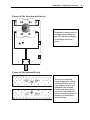
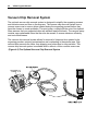
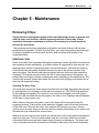
1
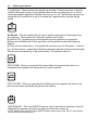
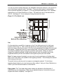
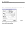
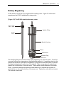
VE-810 Engraver
Operations Manual
Vision Engraving & Routing Systems
17621 N. Black Canyon Hwy.
Phoenix, AZ 85023
Technical Support 602-439-0700
Fax 602-439-0500
www.visionengravers.com
Copyright © 2007 Vision Engraving & Routing Systems
(A Division of Western Engravers Supply, Inc.)
All Rights Reserved
This publication is protected by copyright, and all rights are reserved. No part of this manual may be
reproduced or transmitted by any means or in any form, without prior written consent from Vision.
Limits of Liability/Disclaimer of Warranty for this Equipment Manual
The information contained within this manual has been carefully checked and is believed to be accurate,
however, Vision makes no representations or warranties for this manual, and assumes no responsibility for
inaccuracies, errors, or omissions that may be contained within this manual. In no event shall Vision be
liable for any loss of profit including (but not limited to) direct, indirect, special, incidental, consequential, or
other damages resulting from any defect or omission in this manual, even if previously advised of the
possibility of such damages.
In the interest of continued product development, Vision reserves the right to make improvements to this
manual and the products it describes at any time, without notice or obligation.
Table of Contents
iii
Table of Contents
CHAPTER 1 - BEFORE YOU BEGIN..................................................................................5
INTRODUCTION ....................................................................................................................5
SAFETY ..............................................................................................................................5
UNPACKING AND TAKING INVENTORY .....................................................................................6
MACHINE DESCRIPTION & TERMINOLOGY ..............................................................................7
CHAPTER 2 - INSTALLATION .........................................................................................13
SOFTWARE INSTALLATION ..................................................................................................13
CONNECTING THE TABLE ....................................................................................................20
CONFIGURING THE COMPUTER ...........................................................................................29
CHAPTER 3 - OPERATIONS ............................................................................................31
THE FRONT PANEL ............................................................................................................31
HOLDING DOWN MATERIAL ..................................................................................................36
DIAMOND DRAG ENGRAVING ..............................................................................................39
ROTARY ENGRAVING .........................................................................................................41
BURNISH ENGRAVING.........................................................................................................43
CHAPTER 4 - OPTIONAL ACCESSORIES ......................................................................47
CLAMPING DEVICES ...........................................................................................................47
VACUUM CHIP REMOVAL SYSTEM .......................................................................................52
CHAPTER 5 - MAINTENANCE .........................................................................................53
REMOVING CHIPS ..............................................................................................................53
LUBRICATION.....................................................................................................................54
CHANGING THE MOTOR BELT..............................................................................................56
CHANGING THE MOTOR BRUSHES .......................................................................................58
CLEANING THE FAN FILTER .................................................................................................61
REPLACING THE EXTERNAL FUSE ........................................................................................62
CHAPTER 6 - TROUBLESHOOTING ...............................................................................65
ENGRAVING PROBLEMS......................................................................................................65
MECHANICAL PROBLEMS ....................................................................................................68
INDEX ................................................................................................................................59
iv
VE810 Engraver Manual
0BChapter 1 - Before You Begin
5
Chapter 1 - Before You Begin
Introduction
About This Manual
This manual is designed to provide you with information about your Vision VE-810—
VE-810XD engraver, beginning with unpacking the machine and continuing through
installation and lifetime machine maintenance. This manual does not attempt to teach
you how to engrave, how to use a computer or how to use your engraving software.
Some previous knowledge of engraving terms and the engraving process is assumed.
For information on the Vision Engraving Software, see the Vision Engraving
Software manual. For more information on your individual computer system, see your
computer’s user manual or contact your computer distributor.
Safety
Safety Precautions for the VE-810 Engraver
¾ Keep hands clear of the bottom of the spindle during operation.
¾ Always stop the machine before making any adjustments.
¾ Do not operate the machine with the covers removed.
¾ Wear safety glasses when cutting any materials that emit chips.
¾ Use extreme caution when inserting or removing cutters.
¾ Before any servicing, disconnect the power cord.
¾ To avoid electric shock or equipment damage, ensure that the control unit is
connected to the appropriate electrical source as noted in the installation procedures.
¾ Never operate the equipment with damaged or frayed power cords, loose connections,
or exposed extension cords where someone can step on the cord and create a tripping
hazard.
¾ Be sure to hold the plug, not the cord, when disconnecting the controller from an
electrical socket or power source.
6
VE810 Engraver Manual
¾ Place the machine in a location with low humidity and a minimum of dust. Avoid
placing the equipment in direct sunlight or in locations with excessive heat. Follow the
maintenance instructions for proper cleaning of the controller air filter.
¾ If your machine does not operate properly; in particular, if there are any unusual
sounds or smells coming from it, immediately unplug it and contact a service
technician or your local distributor.
¾ Unplug the machine when it is going to be left unused for an extended period of time.
Unpacking and Taking Inventory
The VE-810 engraving system has been shipped in one carton, unless other accessories
have been ordered with the machine that will not fit in the box. Examine the condition of
the box for external damage. In the event of apparent external damage, notify your
shipping carrier upon receipt, and call your sales representative or Vision immediately.
Note: The shipping container is considered reusable and should be stored for use in the
event of service need or upgrade.
Step1:
Open the foam packed shipping carton. In the top of the carton will be a cardboard box
with all of the machine accessories (including this manual). Open the accessory box and
the following items should be included:
9
9
9
9
9
9
9
9
9
9
9
9
9
9
9
1 VE-810 or VE-810XD Machine
1 VE-810 Warranty Card
1 Vision All Products CD
1 VE810 Table Manual
1 Vision Software Manual
1 Vision Font Catalog
2 Spare 1.5 Amp Fuses (.6 Amp fuses when machine is 220 volt)
1 Power Cord
1 Serial Interface Cable
1 USB Cable
1 Interface Cable Adapter (25 pin to 9 pin)
1 Extra 13 3/4“ Motor Belt
1 Allen Wrench Set
1 Cutter Wrench
1 Quick Lock Vice (mounted on the T-Slot table)
Check to see that all of the items are included. Should any of the contents be missing,
damaged, or of the incorrect type, please call your sales representative or Vision
immediately.
Step 2:
Prepare a clean, level surface to put the engraving machine on. Carefully lift the machine
out of the carton and place it on the table.
0BChapter 1 - Before You Begin
7
Step 3:
After unpacking the machine, make sure that you SAVE THE CARTON, FOAM PACK and
ANY OTHER BOXES. They can be reused in the event the system must be transported
to another location or returned for service. Improper packaging for shipment can damage
the machine and may void the warranty.
Machine Description & Terminology
This chapter briefly describes the major components of the VE-810 table. Figure 1.1
shows a labeled drawing of the VE-810 Engraver. This chapter will help you identify the
parts of your table discussed elsewhere in the manual.
*Optional equipment such as accessory vises, clamps, fixtures or vacuum systems
may have been included with your system. For information regarding this
equipment, see the individual instructions for these options. For descriptions of
controllers, computers, and software used in your system, see the manuals from
the manufacturers of these units.
TABLE SPECIFICATIONS:
Z-Axis Clearance:
1 inch (25.4 mm)
(Definition: the distance between the bottom of the spindle and the work surface)
Z-Axis Stroke:
1 inch (25.4 mm)
(Definition: the travel distance of the Z-axis mechanism or spindle)
Table Resolution:
.001 inch
(Definition: the smallest controlled motion the table is capable of)
Engraving Area:
8” x 10“ (203.2 mm x 254 mm)
Overall Dimensions:
14 1/2” Tall x 19“ Wide x 22” Deep
368 mm Tall x 483 mm Wide x 559 mm Deep
Table Top:
Removable T-Slot
Shipping Weight:
65 lbs.
Shipping Dimensions:
27“ x 22” x 19“
8
VE810 Engraver Manual
0BChapter 1 - Before You Begin
9
DEFINITION OF TERMS (see Figure 1.1)
1. X-Axis Leadscrew - The screw that drives the left to right motion of the machine.
2. X-Axis Linear Rails - The 1/2” round rails that the carriage assembly rides on.
3. Y-Axis Linear Rails - The 1/2” round rails that the t-slot table rides on.
4. Y-Axis Leadscrew - The screw that drives the front to back motion of the machine.
5. T-Slot Table - Also referred to as the work surface, this aluminum bed supported by
the Y-Axis linear rails allows placement of the engraving material or special clamps and
fixtures. The slots in the table are shaped with an upside-down T, with the bottom of the T
being a single-line slot across the top of the table. The slots are used to hold various
accessory holders, clamps, and jigs.
6. Front Panel - This is the area in which you control the table movement. You can start,
stop, pause, cancel a job and set the spindle surface. Also, you can control the speed at
which the table moves and the spindle RPM.
7. Quick Lock Vise - This is the clamp assembly that is included with the VE-810
Engraver that allows you to lock your material on the T-Slot table.
8. Table Home Position - This is the place on the T-Slot table where you position your
engraving material. All work is referenced from this position.
9. Spindle - This is the part where the engraving cutters are inserted and adjusted for
depth of cut.
10. Spindle Motor Pulley - This is where the motor belt runs from. It runs from the
spindle motor pulley to the spindle causing the spindle to turn. (The spindle motor pulley is
hidden by the cover. In order to see it, you must remove the covers).
10
VE810 Engraver Manual
(Figure 1.1) The VE-810 top view
(See Figure 1.2)
11. Spindle Up/Down Knob - This knob raises and lowers the spindle when the power is
off. You will see it turn as the spindle moves up and down while engraving.
12. Down Pressure Spring Adjust - This knob adjusts the amount of pressure that the
spindle applies on the material being engraved. Looking down from the top, turning it
clockwise will increase pressure and turning it counter-clockwise will decrease pressure.
13. Spindle Pulley - This is the top part of the spindle where the motor belt rides.
14. Spindle Micrometer - This is the part of the spindle that you adjust to set the depth of
engraving. Turning it to the right will cause the engraving to be deeper.
15. Spindle Nose Cone - This is the part of the spindle that rides on the material while
engraving. The cutter protrudes from the bottom of the nose cone creating your depth of
cut.
(Figure 1.2) The VE-810 carriage view
0BChapter 1 - Before You Begin
11. Spindle Up/Down Knob
12. Down Pressure Spring Adjust
13. Spindle Pulley
14. Spindle Micrometer
15. Spindle Nose Cone
0
11
1BChapter 2 - Installation
13
Chapter 2 - Installation
Software Installation
The VISION installation program guides you step-by-step. All the information you need
appears on the screen as you install the program. Read each screen carefully and follow
all prompts. If you make an error in the installation, do not panic. All setup information
can be changed later from within VISION.
While running Windows, insert the VISION CD-ROM into the CD drive. If your CD-ROM
drive has the auto start feature enabled, the Vision Installation will start automatically. If
the auto start is not enabled, then you will need to do the following:
Select Start… Run… from the toolbar on the Windows desktop.
Type the location of the CD drive followed by ”:\setup.exe“ in the command line.
14
VE810 Engraver Manual
Click on OK...
The installation process
will now begin.
Click on Next…
Select Vision Windows™
Engraving Software and
click Next…
Note: You can install a demo version of Vision Pro at a later time if you would like. This
will allow you to evaluate the Vision Pro program.
The Vision Software installation will now continue.
1BChapter 2 - Installation
Please Note:
You must be logged to
Windows with
administrative
privileges. Otherwise,
Vision may not install
properly.
Click on Next…
The Vision Software License Agreement will now be shown. In order to continue the
Vision Installation, you must Accept this agreement.
15
16
VE810 Engraver Manual
Select a folder
or leave the default
folder as is and
click Next….
Select Complete
Installation and
click Next…
Select your
preferred language
and click Next…
1BChapter 2 - Installation
Select VE-810
Engraver and
click Next…
Select your
VE-810 model
and click Next…
17
18
VE810 Engraver Manual
Select a Program
Group Name or
leave it as it is and
select Finish
You will see the
Installation bar.
The software
installation is
now complete.
Select OK
Click OK
To run the Vision software, select the Vision icon from the desktop or from the Start Menu
- Programs - Vision Engraving Software group.
1BChapter 2 - Installation
19
IMPORTANT: This procedure must be followed before the Vision software will operate
properly.
1. Run the Vision software by clicking the Vision icon on the desktop of your computer.
2. Go to the System menu and then to Register software.
3. Please call 1-888-637-1737, 602-439-0700, or email [email protected]
with the following information:
a. Your company name
b. Address
c. Phone number
d. Email address
e. Vision machine serial numbers
f. The upgrade request number shown on the Register software screen in
Vision.
4. In the Upgrade Code box on the registration screen, type the word demo and click
OK. This will allow the Vision software to run for 14 days until the permanent
password is emailed or given to you from Vision.
5. You can now run the Vision software.
6. Once the password is emailed to you or given to you over the phone, go back into
the Vision software.
7. Go to the System menu and then to Register software in the Vision software.
8. Enter the password given to you in the Upgrade Code box and click OK.
9. The software is now completely registered.
Please give Vision a call if you have any questions at 602-439-0700.
20
VE810 Engraver Manual
Connecting the Table
There are two connections that must be made to the VE-810 engraver. The power input
and the serial or USB connection (See Figure 2.1)
(Figure 2.1) The VE-810 rear view
USB Connection
Power Input
Serial Connection
Fan
Power Switch
The power input is where you plug the power cord into the VE-810. The VE-810 can
accept 110 volt or 220 volt power depending on which option you’ve chosen. If your
system is configured for 220 volts, a yellow 220 volt label will be affixed to the back of
your machine. If there is no 220 volt label DO NOT PUT 220 VOLT power to the machine
as serious damage will occur.
The serial connection is where you connect the computer to the VE-810. The VE-810
accessory box contains a white serial cable. Connect one end to the VE-810 and screw in
the thumbscrews. The other end connects to your computer.
Your computer will have one of two different types of serial port connectors on the back.
One will be a 9-pin connector and the other will be a 25-pin connector. If you have a 9-pin
connector, you can plug the white serial cable directly into the computer. If your computer
has a 25-pin connector, you can use the 9-pin to 25-pin adapter included with the VE-810
to connect the cable to your computer. (See Fig 2.2 below)
(Figure 2.2) The 9 pin and 25 pin plug
1BChapter 2 - Installation
If no serial port is available on the PC, it can be connected to a USB port. Please follow
the steps below to connect and configure the USB connection.
1. Make sure that the Vision All Products CD is installed in the CD ROM drive of the
PC. Important: The Vision All Products CD must be in the CD ROM drive before
proceeding.
2. Plug one end of the USB cable into the VE810 and the other end into the PC.
3. The message below will appear in the lower right corner of the screen.
4. The following screen will appear. Select “No, not this time” and select Next.
5. The following screen will appear. Select “Install from a list or specific location
(Advanced)” and select Next.
21
22
VE810 Engraver Manual
6. Select “Search removable media (floppy, CD-ROM..)” and select Next.
7. The following screen will appear. Select “Continue Anyway”.
8. The following screen will appear. Select “Finish”.
1BChapter 2 - Installation
9. The following screen will appear. Select “No, not this time” and select Next.
10. The following screen will appear. Select “Install from a list or specific location
(Advanced)” and select Next.
11. Select “Search removable media (floppy, CD-ROM..)” and select Next.
23
24
VE810 Engraver Manual
12. The following screen will appear. Select “Continue Anyway”.
13. The following screen will appear. Select “Finish”.
14. You will see the message below in the lower right corner of the screen.
1BChapter 2 - Installation
15. Select the Start menu in the lower left corner of the screen. Right mouse click on
My Computer and select Manage.
16. The following screen will appear. Select “Device Manager” on the left side.
17. Double click on “Ports (COM & LPT)” on the right side.
18. Double click on “USB Serial Port (Com3)”. Note: The com number shown may be
different then 3.
25
26
VE810 Engraver Manual
19. The following screen will appear. Select the “Port Settings” tab.
20. Change the “Bits per second:” to 19200 and the “Flow control” to Hardware as per
the picture below making sure the other settings match the screen below also.
1BChapter 2 - Installation
27
21. Select the “Advanced” button. The following screen will appear.
22. Change the “COM Port Number:” to COM1 and select OK. Note: If COM1 shows it
is in use, select COM2.
23. Select OK.
28
VE810 Engraver Manual
24. Select the X in the upper right corner to close the screen below.
The USB port is now configured properly.
1BChapter 2 - Installation
29
Configuring the Computer
In order for the VE-810 to run properly, you must configure your computer’s serial port. If
the machine is connected through the USB cable, please disregard this section as it was
done in the previous section. To do this, follow this sequence: Right mouse click on the
My Computer icon on your Windows desktop. Go to manage. Click on Device Manager.
Double click on Ports and then double click on the serial port that the engraver is
connected to. Click on Port Settings. The settings should look like the picture below. If
not, change them to match.
Click on OK twice and then re start Vision.
Your computer is now configured to run Vision with the VE-810 Engraver.
2BChapter 3 - Operations
31
Chapter 3 - Operations
The Front Panel
The front panel controls all of the movement and speeds of the VE-810. Below is a
picture of the front panel.
X-Y Speed - This knob controls how fast the VE-810 will engrave. Turning the knob
clockwise will increase the speed and turning the knob counter clockwise will decrease
the speed.
You would change the engraving speed depending on the type of material you are
engraving and the type of cutter you are using. If you are using a diamond drag cutter
(non-rotating), you can generally run the machine very fast. If you are using a rotary
cutter, you will need to adjust the speed depending on what type of material you are
cutting. Harder materials such as acrylic and engravers brass will need to be engraved at
a slower speed. Softer materials such as engraving plastic can be engraved at a faster
speed.
A rule of thumb for setting the engraving speed is to start off engraving at a slow speed.
You can gradually increase the engraving speed while the machine is engraving. Keep
increasing the speed until you get to a speed where it sounds like the machine is working
freely. If your speed is too fast, the machine will sound like it is working very hard, or
putting a heavy load on the engraving spindle. If this happens, you can possibly dull the
engraving cutter or the engraving quality will not be very good.
32
VE810 Engraver Manual
Z Speed - This knob controls how fast the spindle will move down into the
material. Clockwise is faster, counter-clockwise is slower. Typically, you can leave this all
the way clockwise, unless you are engraving into hard materials such as Acrylic or deep
engraving into metals. In cases such as these, slow the speed down (counterclockwise).
Spindle Speed - This knob controls the revolutions per minute (RPM) of the engraving
spindle. Turning the knob clockwise will increase the RPM, and turning the knob counterclockwise will decrease the RPM.
You would change the RPM of the engraving spindle depending on the type of material
you are engraving or for different sizes of engraving cutters. The harder the material you
are using, the higher the RPM you would use. Also, the larger the cutter you are using,
the higher the RPM you would use.
A rule of thumb for setting the spindle speed is to start out at a higher RPM. You can
gradually lower the RPM while the machine is working. Keep lowering the spindle speed
until the spindle sounds like there is a load (or drag) on the spindle. When you reach that
point, you should turn the spindle speed knob up a little bit.
Start - The start button is used to start the engraving machine. You can tell that there is a
job in the VE-810 when the green light above the start button is flashing on and off. When
it is flashing, pressing the start button will start engraving. Also, if you have pressed the
pause or stop button to stop the engraving, pressing the start button will resume the job.
2BChapter 3 - Operations
33
Pause - The pause button is used to momentarily stop the machine from engraving. If
you press the pause button while the machine is engraving, the VE-810 will wait until the
end of the current letter or logo that it is engraving and then lift the cutter up, shut the
engraving motor off and stop. Pressing the start button will resume the engraving where it
left off.
Stop - The stop button is used to stop the machine from engraving. If you press the stop
button while the machine is engraving, the VE-810 will stop immediately, shut the
engraving motor off and lift the cutter up. Pressing the start button will resume the
engraving where it left off. While stopped, the Goto Home Button and Goto Offset Button
will return the cutter back to home or to the offset.
Hint: Holding the ALT button down
while pressing any jog button will
increase the jog speed.
X & Y Jog buttons - The X & Y jog buttons are used to move the position of the spindle
on the T-Slot table work area. The X jog buttons will move the engraving spindle left and
right. The Y jog buttons will move the t-slot table front to back. The machine will jog at the
speed that the XY speed knob is set at. Increase the XY speed knob to increase the jog
speed.
Hint: Holding the ALT button down
while pressing any jog button will
increase the jog speed.
34
VE810 Engraver Manual
Z-Jog Buttons - These will move the spindle up and down. These buttons are commonly
used for setting the surface of your material when you are not using the prox, or the lift
above the material regardless of whether the prox is on or off. The machine will jog at the
speed that the Z speed knob is set at. Increase the Z speed knob to increase the jog
speed.
Set Surface - The set surface button is used to set the surface point of the material you
are engraving. The procedure for setting the surface is as follows:
a) Use the X & Y jog buttons to move the spindle over the material to be engraved.
b) Press and hold down the Z down jog button until the spindle touches the engraving
material.
e) Press the set surface button. The spindle will now move up to its lift position. Use the Z
up or Z down buttons to adjust the lift between characters and then press set surface again.
This will move the spindle up to the home position. The surface is now set.
GOTO HOME - When you press the Goto Home button the engraver will return to its
mechanical home position and cancel the job from the machine.
GOTO OFFSET - When you press the Goto Offset button the engraver will return to the
previously set offset and cancel the job from the machine.
LIMITS ON/OFF - The Limits ON/OFF button is used to turn the limit switches on and off.
When the limit switches are active, the light above the button comes on.
NOTE: When holding down the Limits ON/OFF button while turning on the VE-810, the machine
will start with the limit switches off.
2BChapter 3 - Operations
35
B1 - The B1 button only works when using the Vision Software Program. When you press
this button, the controller will re-engrave the previously engraved job. If you press this
button while a job is engraving, the table will return to the home position and wait for you to
press the START button to re-engrave the job.
NOTE: The B1 button does nothing when using the Vision-PRO Software.
B2 - The B2 button only works when using the Vision Software Program. When you press
this button while a job is engraving, the table will backup one character. Each time you
press the B2 button, the table will move back another character until it reaches the first
character of the job. You will need to press the START button to resume engraving from
that point.
NOTE: The B2 button does nothing when using the Vision-PRO Software.
B3 Button - The B3 button only works when using the Vision Software Program. When you
press this button while a job is engraving, the table will backup one line. Each time you
press the B3 button, the table will move back another line until it reaches the first line of
the job. You will need to press the START button to resume engraving from that point.
NOTE: The B3 button does nothing when using the Vision-PRO Software.
4th AXIS Button - This button allows for a rotary axis to be used. This is for the optional
pen rotary attachment.
PROX ON/OFF Button - This button allows you to turn the Proximity Sensor on and off.
The Prox allows the spindle to sense where the surface you are engraving is. This feature
works when engraving with a nose cone or diamond drag only; it is not designed for nonnosecone engraving. When the light is green, the Prox is on, when its red, the Prox is off.
36
VE810 Engraver Manual
SPINDLE ON/OFF Button - You can turn the spindle on and off by pressing this button.
When the light is red, the spindle is off. When the light is flashing green and red, the
spindle is on. When the light is green, the spindle will automatically turn on and off at the
beginning and end of the engraving job. If you depress the PAUSE or STOP button, the
spindle will turn off for safety reasons. Always make sure you have the spindle turned on
when appropriate, otherwise you may run the risk of breaking your cutter.
AUX ON/OFF Button - This button will turn on and off the auxiliary output on the rear of
the machine. (This will most likely be used for your vacuum system.) When the light is red,
the auxiliary power is off. When the light flashes green and red, the auxiliary power is on.
When the light is green the auxiliary power will automatically turn on and off at the
beginning and end of the engraving job. If you depress the STOP button, the auxiliary
power device will turn off for safety reasons.
SET OFFSET Button - Use the Jog Buttons to move the spindle to a point you want to be
the offset position. Press the Set Offset Button. This is now set as your new offset
position.
Alternative Button – Holding this button while using the X, Y or Z jog keys will increase the
jog speed.
Holding down material
There are many ways to hold material down on the t-slot table. One of the major things to
remember is that the material must be placed in the upper left corner of the T-slot table
(unless you are using a versa vise attachment). This will insure that the engraving is in
the correct position on your material if the machine is homed correctly.
2BChapter 3 - Operations
37
You can use either double-sided tape, the ”MultiMat“ hold down material, or the quick lock
vise to hold down material to the T-slot table. (There are other types of optional hold
down methods explained in Chapter 4.) You can get double-sided tape or the ” MultiMat “
material from your Vision Distributor or Vision. The quick lock vise is included with the
VE-810. (See figure 3.1 for an example of using the quick lock vise.)
(Figure 3.1) The Quick Lock
Vise
Put the material you would like to engrave on the T-slot table and push it to the home
position corner (Fig 3.1). Next, loosen the quick lock vise locking screw and slide the
quick lock vise so that there is about 1/16 of an inch gap between the edge of the vise and
the material. Tighten the quick lock vise locking screw. Once this is done, the material
can easily be tightened up by turning the quick lock vise handle. When you want to
change the engraving material, simply loosen the quick lock vise handle, remove the
engraved material, put the new material in and tighten up the quick lock handle.
Note: For larger pieces of material, you may need to put a small piece of double-sided
tape on the T-slot table in the middle of the engraving material. This will keep the material
from bowing in the center.
The quick lock vise will only work on square or rectangular material. To hold down
irregular shaped objects, you must use some other method. Ask your Vision Distributor or
Vision if you need more information on this feature.
Edge guides: The T-slot table edge guides need to be adjusted to the thickness of
material that you are engraving. If they are not adjusted properly, the machine may not
engrave the letters completely. See figure 3.2.
38
VE810 Engraver Manual
(Figure 3.2) The Edge Guides
Edge Guide
Thumbscrews
Edge Guides
Edge Guide Thumbscrews
To adjust the edge guides, place the material you would like to engrave in the home
position. The edge guides should be level or slightly below the engraving material. If they
are not, loosen the edge guide thumbscrews and lower the edge guides. Tighten the
edge guide thumbscrews. The edge guides are now adjusted properly.
2BChapter 3 - Operations
39
Diamond Drag Engraving
In this section, we will set up to engrave with a non-rotating cutter, such as a diamond
drag cutter. Figure 3.1 (below) shows the VE-810 spindle with the optional diamond drag
adapter and how to install the adapter.
(Figure 3.1) The VE-810 spindle with diamond drag adapter
Spindle Pulley
Spindle Housing
Pointer
10
Retainer Ring
Nose Cone
Micrometer
Diamond
Drag Adaptor
To install the diamond drag adapter, you must first remove the retainer ring and nose. To
do this, unscrew the retainer ring from the micrometer. Next, screw the diamond drag
adapter onto the micrometer.
Turn the VE-810 Engraver on by flipping the switch on the back left side of the machine.
Set up the job you would like to engrave in the Vision Software. (For more information on
this, see the Vision Engraving Software manual.) Put the material on the T-slot table as
described in the previous section. Make sure that the prox is turned on and the light is
green on the prox button. If it is red, press the PROX button and it will change to green.
Make sure the SPINDLE ON/OFF button is red. If not, press the button until it turns red.
40
VE810 Engraver Manual
This will turn the spindle motor off for diamond drag engraving.
From the Vision software, press the F9 key to send the job to the VE-810 engraver. The
following screen will appear:
Click OK
You will see the green light near the start button start to flash. This means that there is a
job in the VE-810. Now press start. The job should now engrave. If there are any
problems, press the stop button immediately.
2BChapter 3 - Operations
41
Rotary Engraving
In this section, we will set up to engrave with a rotating cutter. Figure 3.2 on the next
page shows the VE-810 spindle with a rotary cutter.
(Figure 3.2) The VE-810 spindle with rotary cutter
Spindle Pulley
Spindle Housing
Pointer
10
Micrometer
Retainer Ring
Nose Cone
The first thing that you need to do when rotary engraving is to zero the cutter. To do this,
you must first turn the micrometer so that the pointer points to 0. Insert the cutter into the
spindle and screw the cutter knob completely in. Note that the cutter will screw in counterclockwise looking down from the top of the spindle. Take a scrap piece of material and
place it flat on the bottom of the nose cone. There will be a small setscrew in the cutter
knob. Loosen the setscrew and push the cutter down until it touches the flat piece of
material that you have at the bottom of the nose cone. Tighten the cutter knob set screw.
The cutter is now zeroed.
42
VE810 Engraver Manual
Now we must adjust the depth of cut. The depth you will need to set depends on the type
of material you are cutting. You can generally find out how deep to cut engraving plastic
from the manufacturer or distributor. As a general rule, you can start out shallow and
increase the depth while you are engraving. Since the cutter is zeroed, we will not get
any depth right now, so let’s set the depth. Turn the micrometer to the right 7 clicks. This
will engrave at a depth of .007 of an inch. If you need more depth, turn the micrometer to
the right. If you need less depth, turn the micrometer to the left. Each click is .001 of an
inch.
Turn the VE-810 Engraver on by flipping the switch on the back left side of the machine.
Set up the job you would like to engrave in the Vision Software. (For more information on
this, see the Vision Engraving Software manual.) Put the material on the T-slot table as
described in the previous section. Make sure the PROX button light is green. If it is red,
press the PROX button until the light on the PROX button is green. Make sure the
SPINDLE ON/OFF button is green. If not, press the SPINDLE ON/OFF button until it turns
green. Do the same fo the AUX button if you are usuing a vacuum system. From the
Vision software, press the F9 key to send the job to the VE-810 engraver. You will get the
following screen:
Click OK
You will see that the green light near the start button will start to flash. This means that
there is a job in the VE-810. Now press start. The job should now engrave. If there are
any problems, press the stop button immediately.
2BChapter 3 - Operations
43
Burnish Engraving
In this section, we will set up to engrave with a burnishing cutter. Figure 3.3 on the next
page shows the VE-810 spindle with a burnishing cutter and an optional ”EZ Rider“
burnishing adapter.
(Figure 3.3) The VE-810 spindle with burnishing cutter
Burnishing is different than standard rotary engraving mainly because you do not use the
nose cone to set the depth of cut. Burnishing does not actually cut deep into metals;
rather it cuts the lacquered surface off of the coated brass and aluminum material. To
effectively burnish, it is recommended to use an optional ”EZ Rider“ burnishing adapter.
This helps to control the pressure of the cutter on to the material.
Screw the ”EZ Rider“ into spindle. Note that the ”EZ Rider“ will screw in counter-clockwise
looking down from the top of the spindle. Next, insert the cutter through the ”EZ Rider“
and through the spindle so that the cutter sticks out below the nose cone approximately
1/8 of an inch. Tighten the setscrew in the ”EZ Rider“.
44
VE810 Engraver Manual
Turn the VE-810 Engraver on by flipping the switch on the back left side of the machine.
Set up the job you would like to engrave in the Vision Software. (For more information on
this, see the Vision Engraving Software manual.) Put the material on the T-slot table as
described in the previous section. Make sure the PROX is off and red. If the PROX light
is green, press the PROX button until it turns red. Use the X & Y jog keys to move the
spindle out over the material. Press and hold down the Z down jog button until the cutter
touches the engraving material. Press the Z down jog key a little bit more. There should
be a small gap underneath the set screw in the EZ Rider. This will ensure that the depth
of cut is consistent. Press the set surface button. The spindle will lift up a small amount.
Make sure there is some clearance between the bottom of the cutter and the material you
are engraving. If not, use the Z jog button to raise or lower the spindle so there is some
clearance. Press the set surface button again. The spindle will now move to its original
position. The surface is now set.
From the Vision software, press the F9 key to send the job to the VE-810 engraver. You
will get the following screen:
Click OK
You will see that the green light near the start button will start to flash. This means that
there is a job in the VE-810. Now press start. The job should now engrave. If there are
any problems, press the stop button immediately.
2BChapter 3 - Operations
45
Engraving a job at a position other than the top left
corner of the t-slot
If you would like to put your material to be engraved at a position other than the standard
home position, place your material on the t-slot table in the position you desire. Use the
XY jog buttons to move the spindle to the upper left corner of the piece you would like to
engrave. Now press the SET OFFSET button. The machine will now engrave from that
position.
Note: The machine will engrave from that point until the machine is turned off or you clear
the offset. To clear the offset press the GOTO HOME button. After the machine has
moved to the home position, press SET OFFSET. The home is now set back to the
default position.
3BChapter 4 - Optional Accessories
47
Chapter 4 - Optional Accessories
Clamping Devices
The optional versa vise is used for holding small or odd shaped items. It can be used as
a stand-alone clamp or other clamps can be used with the versa vise. Some of the other
types of clamps are explained later in this chapter. For a complete list of holding clamps,
please ask Vision for an accessory catalog or visit our web site at
www.visionengravers.com.
To install the versa vise, you must remove the T-slot table. To do this, remove the four
screws labeled in figure 4.1.
(Figure 4.1) Removing the t-slot table
T-Slot table hold
down screws
The T-slot table will now come off. Place the versa vise on to the flat plate where the Tslot table was and move it to the upper left corner of the plate. Included with the versa
vise should be 4 dowel pins. The dowel pins are used for locating the versa vise in the
correct position. See figure 4.2 for screw and dowel placement.
48
VE810 Engraver Manual
(Figure 4.2) Mounting the Versa Vise
Once the versa
vise is mounted,
you can set up to
engrave using
two different
home points.
One way is to use
a top left origin
and the other way
is to use a top
center origin.
Figure 4.3 shows
the two different
origin points.
(Figure 4.3) Versa Vise home points
If you insert the material in the top left
origin, you will set up to engrave the
same way that is discussed on page 33.
If you set up to engrave as a top center
origin, you will need to make some
changes. The first thing that you need to
do is to place your object into the versa
vise. Once it is in, use the X jog key to
move the spindle over to the top of the
object. Then use the Y jog key to move
the spindle over the top edge of the
material. Then Press SET OFFSET.
When you send the job to the engraver
(F9), you will change the driver select to
VeTCtr.cdf. This will tell the machine that
you are using the top center. Figure 4.4
shows where to change to the VeTCtr
driver.
3BChapter 4 - Optional Accessories
(Figure 4.4) Changing to Top Center Origin in Vision
Other clamps can be added to the versa vise to allow for the holding of irregular shaped
objects. Here are some figures that show different configurations.
(Figure 4.5) The Versa Vise with 9 inch jaws
These clamping bars are
specially designed to hold
both 1/16” and 1/8“ thick
materials and allow
engraving up to the edge of
the material without
nosecone interference.
Other uses include holding
metal engraving stock,
name badges or other
rectangular shapes.
49
9
8
7
6
5
4
3
2
1
1
2
3
4
5
6
7
8
9
50
VE810 Engraver Manual
(Figure 4.6) The Versa Vise with Universal Seal & Medallion holder
9
8
7
6
5
4
3
2
1
1
2
3
4
5
6
7
8
9
This universal clamp will
hold 1-3 round objects at a
time. It also has a place for
the ”eye“ of a medallion or
tag. This clamp may be
used to any diameter of
notary seal.
(Figure 4.7) The Versa Vise with Pen & Seal jig
These jaws enable
engraving on all types of
pens and other small
cylindrical objects. Rotating
the jaws 180º allows
engraving on medallions,
notary seals, pet tags and
other round objects.
3BChapter 4 - Optional Accessories
(Figure 4.8) The Versa Vise with Seal jig
Designed for notary seals of
all diameters. Rotating the
jaw 180º will allow clamping
of both large and small
sizes.
(Figure 4.9) The Universal Pin Jig
This is a true universal
clamp designed for holding
odd shaped items such as
state badges, hearts, and
medallions with unusual
borders, pet tags, jewelry
and more. The dowel pins
may be moved anywhere on
the jaw to accommodate
any odd shape.
51
52
VE810 Engraver Manual
Vacuum Chip Removal System
The optional vacuum chip removal system is designed to simplify the engraving process
and minimize wear and tear on the engraver. The vacuum chip removal system uses a
vacuum nose cone to remove chips created during the engraving process before they
have the chance to create problems. The quiet pump, coupled with the micro fine-layered
filters assures that your unwanted chips are whisked away effortlessly. The vacuum pump
canister uses replaceable filters that can also be reused, to assure maximum efficiency
and cost-effectiveness.
The vacuum chip removal system allows for removal of chips and dust created in the
engraving process, reducing contamination and overheating in the spindle area. Chip
removal also prevents the cutter from skipping over letters due to stray particles. This
vacuum chip removal system is available with or without a Vision vacuum nose cone.
(Figure 4.9) The Optional Vacuum Chip Removal System
4BChapter 5 - Maintenance
53
Chapter 5 - Maintenance
Removing Chips
Vision strives for the highest quality in their manufacturing process to provide you
with the most cost effective, reliable engraving machine in use today. Please
remember that proper maintenance and care is necessary to achieve maximum
product life expectancy.
The engraving environment generates small plastic and metal chips as well as other
particles during operation. As with any machinery, your engraving system should be kept
as clean as possible to minimize wear and tear, and to improve final quality of the
engraved product.
REMOVING CHIPS
Plastic and metal chips, generated during the engraving process, should be removed from
the engraving surface periodically. A portable vacuum is suggested for chip removal, but
applying direct suction to the spindle area is not recommended. Note that this cleaning
can be minimized and greatly simplified through the use of the optional vacuum chip
removal system. The vacuum chip removal system removes chips and dust created by
engraving. This system can also extend the life of other components in the system, as
prompt removal of chips reduces contamination and overheating in the spindle area. The
vacuum chip removal system also keeps the nose cone from skipping over letters due to
chips on the engraving surface.
Cleaning The Nose Cone
The nose cone around the cutter may accumulate dust and chips that cannot be removed
by sucking them off or blowing on them with low-pressure air. CAUTION! High-pressure
air can damage the spindle.) Two types of nose cones are available; one nose cone is
designed to be used with the vacuum system, the other is not. Cleaning methods depend
on the type of nose cone in use.
With a vacuum chip removal system, most of the chips will be removed during the
engraving process. If the suction nozzle becomes clogged, remove the hose connection
to the nose cone. Remove the cutter, then unscrew the vacuum nose cone. Using a
vacuum or an air hose, clean out the nose and the vacuum tube leading to the nose cone.
Reinstall the nose cone and the vacuum hose.
Without a vacuum chip removal system you should remove the cutter before attempting to
clean the nose cone. The nose cone retainer ring, the nose cone, and the micrometer
collar should all be removed and cleaned using a vacuum or blowing air. The three nose
cone components should be removed and cleaned at least every day, and as frequently
54
VE810 Engraver Manual
as necessary. Failure to clean the nose cone regularly will result in premature spindle
failure.
Cleaning the Vacuum Filter (only with the vacuum chip removal option)
On systems with a vacuum chip removal system, frequent cleaning of the vacuum filter is
necessary for proper performance. When engraving with the vacuum filter system, the
filter should be checked and cleaned several times a day, depending on the amount of
engraving done. If the vacuum does not appear to be functioning efficiently, clean the filter
more frequently as needed.
To clean the vacuum filter system, disconnect the vacuum hose from the canister. On the
lid of the canister, note the three wing nuts. Loosen these nuts enough to allow the
attached bolts to swing away from the lid, allowing removal of the lid. Do not loosen the
nuts enough to remove them completely. Remove the canister lid and inside you will find
two filters. Carefully remove the inner, paper filter. (The paper and cloth filters tend to stick
together.) Empty the paper filter, and shake it out completely, being careful not to damage
it, as the filters are reusable. After shaking out the paper filter remove and empty the cloth
filter in the same manner as the paper filter. Do not wash either filter. Place the paper filter
back inside the cloth filter, and place the cloth filter back inside the vacuum canister.
Lubrication
Lubricating the X&Y-Axis Linear Rails
Apply 2-3 drops of light oil (such as 3-in-1 oil) on the rails and rub it in with a paper towel.
Use the X jog button to move the spindle to the right and left to evenly distribute the oil.
Also, use the Y jog button to move the t-slot table front to back to evenly distribute the oil.
This should be done every 3-4 months.
(See Figure 5.1)
Lubricating the X-Y-Z-Axis lead screws
A light lubrication of the X, Y and Z lead screws should be performed once per month.
Use silicone lubricant only. To reach the Z-Axis lead screw, press the Z jog down button to
lower the spindle. This will expose the Z leadscrew so you can spray it with lubricant.
DO NOT use any lubricant other than silicone, as it may become sticky and cause a
buildup that can cause mechanical failure.
4BChapter 5 - Maintenance
55
(Figure 5.1) Lubricating the VE-810
What not to lubricate
Many of the bearings and assemblies in your engraving machine are sealed and/or coated
using special low-friction methods and should not be lubricated.
DO NOT attempt to lubricate the spindle or the spindle bearings. If you suspect lubrication
problems, call your dealer/representative for instructions, as further lubrication may harm
the machine.
DO NOT oil the X or Y stepper motors. None of the motors on the VE-810 require
lubrication. Oiling the stepper motors can permanently damage the motors.
56
VE810 Engraver Manual
Changing the Motor Belt
Over a period of time, the VE-810 motor belt will wear. When the motor belt wears it will
stretch and cause the spindle to slip or stall. When this happens, the motor belt generally
needs to be changed. The following explains the procedure for changing the motor belt.
(Figure 5.2) Cover
Screws
Press the X Jog key to
move the spindle to the
middle of the table. Use a
3/32” Allen wrench and
remove the two cover
screws shown in figure
5.2.
(Figure 5.3) Back Cover Screws
Use a 3/32“ Allen wrench
to remove the 4 back
cover screws shown in
figure 5.3.
4BChapter 5 - Maintenance
57
(Figure 5.4) Spindle Cover
The top cover can now
be pushed to the back.
Remove the front spindle
cover as seen in
figure 5.4.
Spindle Cover
0
(Figure 5.5) Carriage Cover
Remove the four
carriage cover screws
on each side of the
carriage cover using a
3/32” Allen wrench as
seen in figure 5.5.
58
VE810 Engraver Manual
(Figure 5.6) The Motor Belt
The motor belt is now
easily accessible as
seen in Figure 5.6.
Remove the old belt
and put a new one on.
Next, put the three covers that you just removed back on. The motor belt change is now
complete.
Changing the Motor Brushes
The motor brushes on the engraving motor should be inspected annually, and replaced
when worn. The motor brushes are worn when the length of the brush is less than 1/8 of
an inch.
Inspect the brushes for possible replacement annually using the following procedure.
Press the X Jog key to move the spindle to the middle of the table.
CAUTION: Disconnect the power cable going into the back of the VE-810 before
continuing!
(Figure 5.7) Cover Screws
Use a 3/32“ Allen
wrench and remove
the two cover screws
shown in figure 5.7.
(Figure 5.8) Back Cover
Screws
4BChapter 5 - Maintenance
Use a 3/32” Allen
wrench to remove the
4 back cover screws
shown in figure 5.8.
(Figure 5.9) Spindle Cover
The top cover can now
be pushed to the back.
Remove the front
spindle cover as seen
in figure 5.9.
Spindle Cover
0
59
60
VE810 Engraver Manual
(Figure 5.10) Carriage Cover
Remove the four
carriage cover screws
on each side of the
carriage cover using a
3/32“ Allen wrench as
seen in figure 5.10.
(Figure 5.11) Motor Brush Caps
Locate the motor
brush caps.
See figure 5.11
4BChapter 5 - Maintenance
(Figure 5.12) Motor Brush & Cap
Motor Brush
Motor Brush Cap
Use a flat blade
screwdriver to loosen the
motor brush cap. Inspect
the motor brush for length.
If the length is under 1/8
of an inch, the motor
brush needs to be
replaced. See figure 5.12.
Motor Brush Cap
If the motor brush is over 1/8 of an inch, put the existing brush back into the motor and
replace the motor brush cap.
Next, put the three covers that you just removed back on.
Cleaning the Fan Filter
Weekly preventative maintenance should be performed to ensure reliable operation of
your VE-810. It is recommended that the input fan filter be removed weekly and cleaned
to ensure proper cooling of the electronics.
1. Unplug the power cable that goes into the back of the VE-810.
2. Remove the filter guard by using a small flat blade screwdriver to pop the guard open.
See figure 5.13.
3. Remove the filter and blow out the filter with low-pressure compressed air.
4. Replace the filter and filter guard by snapping it back in place.
(Figure 5.13) Cooling fan
61
62
VE810 Engraver Manual
Replacing the External Fuse
If none of the lights on the VE-810 are illuminated, it is possible that the external fuse is
blown. Follow the procedure below to change the external fuses.
1. Unplug the power cable that goes into the back of the VE-810.
2. Locate the fuse holder at the rear of the machine.
See Figure 5.14
3. Use a small flat blade screwdriver to unscrew the fuse holder. Turn the fuse holder
counterclockwise until it pops out.
See Figure 5.15
4. Pull the fuse out of the fuse holder and replace it with a new 5-amp fuse.
5. Slide the fuse holder back into its place, and screw back into place with screwdriver.
(Figure 5.14) External Fuse Location
(Figure 5.15) External Fuse removal
4BChapter 5 - Maintenance
63
64
VE810 Engraver Manual
5BChapter 6 - Troubleshooting
65
Chapter 6 - Troubleshooting
Engraving Problems
Problem: Engraving on the plate is ”slanted“.
Possible solutions:
1. Check material for squareness. Maybe your shear did not cut squarely.
2. Check to see if the material on the table is indeed at a true home and is square to your
T-slot edge guides.
3. Check to insure that the T-slot edge guides are secure and flush to your T-Slot table.
Hint: Always inspect your job before removing your plate from the system. You may be
able to salvage it by re-engraving the job, or at a minimum, you may be able to analyze
the problem and prevent repeating it. Perhaps the plate moved during engraving.
Removing it without inspection would prevent you from detecting this problem.
Problem: You are using a nosecone, but your engraving is ”shallow“ across the top or left
margin of your plate. It engraves properly when the spindle is away from the edge.
Possible solutions:
1. Your nosecone is riding on the T-slot edge guides. Loosen and lower the edge guides
so that they are below the level of your material surface. Retighten the thumbscrews.
2. Check to see if your material is riding on the T-slot edge guides. It’s not hard to miss
during set-up especially if the plate is thin material.
Problem: You are using a nosecone and your engraving is uneven.
Possible solutions:
1. Your spindle is not ”zeroed“ to your material. Follow the steps in ”Chapter 3 - Rotary
Engraving“ to zero your spindle.
2. You are not using enough float and need to adjust the down stroke until your nosecone
touches the material with some pressure.
3. You may be engraving too fast for the type of material you are cutting. Check the
manufacturer’s recommendation. The cutter may be bouncing on the surface. Some hard
materials may exhibit this problem.
4. You may have a defective or broken cutter. Replace it.
5. Your material may be defective.
6. Your vac chip removal system is plugged or the hose is blocked and engraving chips
are caught between the nosecone and the material.
7. The nosecone or vac nose is loose.
66
VE810 Engraver Manual
Problem: ”Shadowing“ occurs while engraving certain materials.
Possible solutions:
1. Leave the protective film on the engraving material during engraving.
2. Use a plastic nosecone instead of a metal one.
3. The nosecone may be damaged. Inspect for burrs or roughness. Try using an emery
cloth to polish the nose.
4. Back off on the spring pressure. Excessive down pressure will leave a rub mark on
almost any plastic material.
Problem: You are not using a nosecone and you have uneven engraving.
Possible solutions:
1. Switch to a nose-riding method.
2. Use a different method of holding the material. If you use double-sided tape, it may be
thick enough to change your surface flatness by a few thousandths.
3. Table tolerances may not be able to maintain the accuracy level you want.
4. Table may not be on a level surface.
5. Make sure the Pressure knob is locked all the way down.
Hint: While it’s true that you can do non-nose riding engraving, it’s not easy to hold any
controlled accuracy on the depth. This takes flat material, a very flat bed and some
degree of skill and confidence. It also takes an application where some amount of uneven
engraving may be tolerated.
Problem: I’m getting ”tails“ or ”swirls“ in the corners of my engraving.
Possible solutions:
1. Your cutter speed is too fast relative to your x-y speed. Slow your spindle speed down
or increase your table speed.
2. Your cutter is worn or damaged. Replace or have re-sharpened.
Problem: I’m getting ”fuzz“, ”fur“ or can see lines in the bottom of my cut showing each
cutter path. I can even see steps in the bottom of my cut.
Possible solutions:
1. Sometimes caused by dull cutters, the wrong cutter, or not enough overlap for each cut.
Try changing cutter size slightly. You may get better clean up.
2. Try taking a second pass cut at .001-.002 deeper. This may clean up the roughness.
3. Resharpen the cutter. There are various cutter angles that can cause these kinds of
problems. There is a relief angle that if too great can cause noticeable ridges in the
bottom of the cut.
4. Ensure that the spindle is square in the mount or block. An unsquare spindle means an
unsquare cutter to the material surface.
5. Turn the spindle speed up.
5BChapter 6 - Troubleshooting
67
Problem: Poor letter quality.
Possible solutions:
1. You may be engraving too fast. Engraving quality improves with the right engraving and
spindle speeds.
2. If you are diamond drag engraving, you have too much down pressure or you are
engraving too deep. Also, check the grain of the material; it should be left to right.
3. You may have a worn or dull cutter.
4. Your material is not securely fastened to the table.
Problem: Ragged Type.
Possible solutions:
1. If the quality of cut is ragged or exhibits steps, you may have play in the cutter. This
could be in the gap between the cutter and the spindle shaft. Maybe the shaft is worn or
the spindle bearings need to be replaced. Once a shaft starts to wear and a cutter is
loose, the problem can worsen quickly.
2. The spindle is loose in the housing or block.
3. The carriage is loose or has excessive play, check the z-axis bearings or slide.
4. Lubricate lead screws with recommended lubricant as explained in Chapter 5 Lubrication.
Problem: My baseline is off.
Possible solutions:
1. You’re not at the mechanical or software home. Maybe the table or carriage was
bumped during set-up. Maybe the previous job was cut short and the system did not
return back to its mechanical home or limit switches. Move the table, bridge or carriage
physically to home or send it home via the software.
2. Check your software layout for keystroke errors.
Problem: While burnishing aluminum I have voids or non-engraved areas.
Possible solutions:
1. Try re-engraving the same plate again. Some of the anodized aluminum plates have
very hard surfaces and two passes are required.
2. Switch to a diamond burnisher. The more common carbide tools may have difficulty
getting through the tough surface and are more easily worn down, thus sometimes
skipping across the surface.
3. Increase the pressure of the z-axis or burnishing adapter.
4. Try other materials. Same reasons as above. Some materials, from some vendors, are
just plain tough.
Hints:
Always try to solve the problems yourself before seeking help. A little patience goes a long
way. Never work on any problem that gets you so frustrated that you become irritated at
the machine, the service technician, or the salesman. It’s only a machine, don’t let it get
the best of you. Contact your dealer.
68
VE810 Engraver Manual
Mechanical Problems
Problem: No X, Y or Z-Axis movement.
Possible solutions:
1. Check that the controller power is on.
2. Check the power cable to make sure it is plugged in properly to the VE-810.
3. If the power cord is plugged in to a power strip, make sure that the power strip is
working properly and turned on.
4. Check to make sure that the X-Y Speed knob on the front panel is turned all the way
clockwise.
5. Ensure that the job has been transferred to the controller (Green start light is flashing).
Problem: System has no movement in any one axis.
Possible solutions:
1. Try to jog the problem axis using the X/Y/Z jog keys on the front panel. If OK, retry the
job.
2. There is possibly a bad microstepper board in the machine. Contact your distributor or
Vision.
Problem: Unusually loud noises during the engraving process.
Possible solutions:
1. Isolate the cause of the unusual noise by:
a. Remove the cutter.
b. Turn the engraving motor to OFF.
c. Run the engraving job, or X/Y jog the system.
If the noise persists, it may be confined to the X, Y or Z-axis. Check for proper lubrication
of lead screws. Follow lubrication instructions in chapter 5 - Lubrication. If the noise goes
away and to further isolate the cause, do the following:
a. Remove the motor belt.
b. Run the engraving motor without starting a job. Loose motor belts may cause
some noises, so removal will narrow down the problem. If the noise is present with
the spindle motor on, check the motor brushes. If there is no unusual noise when
running the spindle motor with no belt attached, do the following:
a. Attach the motor belt.
b. Run the spindle motor and vary the RPM by changing the control unit
potentiometer.
Noise levels may vary. If the noise persists, check the spindle for overheating. Excessive
overheating of the outside housing of the spindle is a sign of defective bearings. The noise
may be caused by the bearings.
5BChapter 6 - Troubleshooting
69
Problem: Spindle is hot.
Possible solutions:
1. Ensure that the nose cone area is free of debris. Check the vacuum system (if used) for
clogging.
2. Inspect the spindle for other obstructions that may prevent proper rotation.
3. The spindle bearings may need to be replaced.
Problem: Spindle motor will not come on.
Possible solutions:
2. Check motor brushes. See chapter 5.
Problem: Motor belt will not stay on pulley.
Possible solutions:
1. Motor belt is probably worn and needs to be replaced. See Chapter 5 - Changing the motor belt
5BChapter 6 - Troubleshooting
INDEX
C
Changing the Motor Belt, 56
Changing the motor brushes, 58
Cleaning the Fan Filter, 61
Configuring the Computer, 29
Connecting the Table, 20
E
Engraving - Burnishing, 43
Engraving - Non Rotating, 39
Engraving - Rotary, 41
Engraving Problems, 65
M
Machine Description & Terminology, 7
Maintenance, 53
Mechanical Problems, 68
R
Replacing the External Fuses, 62
S
Safety, 5
Software Installation, 13
T
H
The Front Panel, 31
Holding down material, 39
U
I
Unpacking and Taking Inventory, 6
Installing The Vision Software, 13
Introduction, 5
V
L
Vacuum Chip Removal System, 52
Versa Vise, 47
Lubrication, 54
71