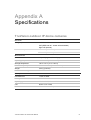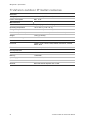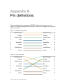
1
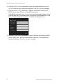
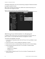
TruVision Outdoor IP Camera User Manual P/N 1072587A-EN • REV 1.0 • ISS 27AUG12 Copyright Trademarks and patents Manufacturer Certification FCC compliance European Union directives © 2012 UTC Fire & Security. All rights reserved. Interlogix, TruVision names and logos are trademarks of UTC Fire & Security. Other trade names used in this document may be trademarks or registered trademarks of the manufacturers or vendors of the respective products. UTC Fire & Security Americas Corporation, Inc. 2955 Red Hill Avenue, Costa Mesa, CA 92626-5923, USA Authorized EU manufacturing representative: UTC Fire & Security B.V. Kelvinstraat 7, 6003 DH Weert, The Netherlands N4131 Class B: This equipment has been tested and found to comply with the limits for a Class B digital device, pursuant to part 15 of the FCC Rules. These limits are designed to provide reasonable protection against harmful interference in a residential installation. This equipment generates, uses, and can radiate radio frequency energy and, if not installed and used in accordance with the instructions, may cause harmful interference to radio communications. There is no guarantee that interference will not occur in a particular installation. If this equipment does cause harmful interference to radio or television reception, which can be determined by turning the equipment off and on, the user is encouraged to try to correct the interference by one or more of the following measures: • Reorient or relocate the receiving antenna. • Increase the separation between the equipment and receiver. • Connect the equipment into an outlet on a circuit different from that to which the receiver is connected. • Consult the dealer or an experienced radio/TV technician for help. 12004/108/EC (EMC directive): Hereby, UTC Fire & Security declares that this device is in compliance with the essential requirements and other relevant provisions of Directive 2004/108/EC. 2002/96/EC (WEEE directive): Products marked with this symbol cannot be disposed of as unsorted municipal waste in the European Union. For proper recycling, return this product to your local supplier upon the purchase of equivalent new equipment, or dispose of it at designated collection points. For more information see: www.recyclethis.info. Contact information Customer support For contact information, see www.interlogix.com or www.utcfssecurityproducts.eu. www.interlogix.com/customer-support Content Chapter 1 Introduction 1 Product overview 1 Features 1 Chapter 2 Installation 3 Installation environment 3 Package contents 4 Cable requirements 4 Camera descriptions 5 Setting up the camera 6 Connecting the devices 6 Accessing the SDHC card 7 Mounting the dome cameras on a ceiling 8 Mounting the bullet camera 12 Using the camera with TVR 60/ TVN 20/ TVN 40/ LNVR and other systems 12 Using the camera with TruVision Navigator 13 Chapter 3 Network and streaming configuration 15 Checking your web browser security level 15 Accessing the camera over the internet 17 Overview of the camera web browser 18 Configuring the camera’s network settings 19 Information about the camera 22 Network parameters 22 Chapter 4 Camera configuration 25 Camera parameters 25 Defining how information is displayed 26 Defining the system time 27 Alarm parameters 28 Events scheduling 28 Defining recording parameters 29 Motion detection alarms 31 Adding extra on-screen text 34 Configuring the video image 34 Chapter 5 Camera management 37 User management 37 Formatting the SDHC card 39 Restoring default settings 40 Upgrading the firmware 40 Rebooting the camera 41 TruVision Outdoor IP Camera User Manual i Chapter 6 Camera operation 43 Logging on and off 43 Live view mode 43 Playing back recorded video 44 Searching event logs 46 Archiving recorded files 48 Controlling zoom and focus 49 Appendix A Specifications 51 TruVision outdoor IP dome cameras 51 TruVision outdoor IP bullet cameras 52 Appendix B Pin definitions 53 Index 55 ii TruVision Outdoor IP Camera User Manual Chapter 1 Introduction Product overview This is the user manual for TruVision Outdoor IP camera models: TVC-N225E-2M-N(-P) (IP bullet camera) TVC-M1245E-2M-N(-P) (1.3MPX WDR bullet camera) TVD-N225E-2M-N(-P) (IP dome camera) TVD-M1245E-2M-N(-P) (1.3MPX WDR dome camera) Features This section describes the camera features. Supports TCP/IP, HTTP, DHCP, DNS, DDNS, RTP/RTCP, PPPoE, SMTP, NTP protocols Programming and setup through a browser interface Live viewing over the network 50/60 Hz selectable flicker control 128dB Wide Dynamic Range (WDR models only) Motorized lens with zoom function Auto focus Supports remote upgrades and maintenance H.264 video compression with dual capability Supports HD (1.3MPX models), 4CIF, 2CIF, CIF and QCIF IP66 weather proof SDHC card for local storage (dome cameras only) Designed to ONVIF and PSIA open standards TruVision Outdoor IP Camera User Manual 1 0BChapter 1: Introduction 2 TruVision Outdoor IP Camera User Manual Chapter 2 Installation This chapter provides information on how to install the TruVision Outdoor IP dome and bullet cameras. Installation environment When installing your product, consider these factors: • Electrical: Install electrical wiring carefully. It should be done by qualified service personnel. Always use a proper PoE switch or a 12 VDC UL listed Class 2 or CE certified power supply to power the the bullet camera, and a proper PoE / PoE+ switch or a 24 VAC UL listed Class 2 or CE certified power supply to power the dome camera. Do not overload the power cord or adapter. • Ventilation: Ensure that the location planned for the installation of the camera is well ventilated. • Temperature: Do not operate the camera beyond the specified temperature, humidity or power source ratings. The operating temperature of the bullet camera is between -10 to +60°C (14°F to 140°F) and outdoor dome is between -40 to +60 °C (-40 to +140 °F) with th eheater and fan on. Humidity is below 90%. • Moisture: Do not expose the camera to rain or moisture, or try to operate it in wet areas. Turn the power off immediately if the camera is wet and ask a qualified service person for servicing. Moisture can damage the camera and also create the danger of electric shock. • Servicing: Do not attempt to service this camera yourself. Any attempt to dismantle or remove the covers from this product will invalidate the warranty and may also result in serious injury. Refer all servicing to qualified service personnel. • Cleaning: Do not touch the sensor modules with fingers. If cleaning is necessary, use a clean cloth with a some ethanol and wipe the camera gently. If the camera will not be used for an extended period of time, put on the lens cap to protect the sensors from dirt. TruVision Outdoor IP Camera User Manual 3 1BChapter 2: Installation Package contents Check the package and contents for visible damage. If any components are damaged or missing, do not attempt to use the unit; contact the supplier immediately. If the unit is returned, it must be shipped back in its original packaging. Package contents: • Camera • Hex wrench • Video cable for testing (except bullet cameras) • User manual • Quick start guide • CD with user manual and TruVision Device Finder. CAUTION: Use direct plug-in UL listed power supplies marked Class 2/CE certified or LPS (limited power source) of the required output rating as listed on the unit. Cable requirements For proper operation, adhere to the following cable and power requirements for the cameras. Category 5 cabling or better is recommended. All network cabling must be installed according to applicable codes and regulations. Table 1 below lists the requirements for the power cables that connect to the camera. Table 1: Recommended power cable requirements Bullet camera: 12 VDC power jack Dome camera: 24 VAC power jack 4 TruVision Outdoor IP Camera User Manual 1BChapter 2: Installation Camera descriptions Figure 1: Outdoor IP dome camera 1. Video output interface 2. LINK LED: The yellow LED is lit when the network is connected. 3. ACT LED: The blue LED blinks when the network is correctly functioning. 4. PWR LED: The red LED is lit when the camera is powered up. 5. Micro SD slot 6. Reset switch. Figure 2: Outdoor IP bullet camera Sun shield Safety cable TruVision Outdoor IP Camera User Manual Mounting bracket Threaded knockout for cable access 5 1BChapter 2: Installation Setting up the camera Note: If the light source where the camera is installed experiences rapid, widevariations in lighting, the camera may not operate as intended. To quickly put the dome camera into operation: 1. Prepare the mounting surface. 2. Connect the power and network cables to the camera. See “Connecting the devices” on page 6. 3. Mount the camera to the ceiling using the appropriate fasteners. See “Mounting the dome cameras on a ceiling” on page 8. 4. Set up the camera’s network and streaming parameters so that the camera can be controlled over the network. See “Chapter 3 Network and streaming configuration” on page 15. 5. Program the camera to suit its location. See “Chapter 4 Camera configuration” on page 25. To quickly put the bullet camera into operation: 1. Prepare the mounting surface. 2. Connect the power and network cables to the camera. See “Connecting the devices” on page 6. 3. Mount the camera to the ceiling using the appropriate fasteners. See Mounting the bullet camera” on page 8. 4. Set up the camera’s network and streaming parameters so that the camera can be controlled over the network. See “Chapter 3 Network and streaming configuration” on page 15. 5. Program the camera to suit its location. See “Chapter 4 Camera configuration” on page 25. Connecting the devices A qualified service person, complying with all applicable codes, should perform all required hardware installation. 6 TruVision Outdoor IP Camera User Manual 1BChapter 2: Installation Note: Do not attempt to extend the power/data cable connection using RJ45 couplers and Cat5 cable. Only use the data cable connection provided. Note: Use 24 VAC or PoE/PoE+. The built-in heater requires the camera to be powered by 24 VAC or PoE+ in order to operate. When powered by standard PoE, the heater is disabled but the camera still functions normally. Figure 3: Connections on the base of the dome cameras 1. Power supply Connect +24 VAC power supply. 2. Ethernet RJ45 PoE port Connect to network devices. Figure 4: Connections of the bullet cameras 1. Power supply Connect +12 VDC power supply. 2. Ethernet RJ45 PoE port Connect to network devices. Accessing the SDHC card Insert an SDHC card up to 32GB for local storage as a backup in case the network fails, for example (see Figure 1 on page 5). The card is not supplied with the camera. Video and log files stored on the SDHC card can only be accessed via the Web browser. You cannot access the card using TruVision Navigator or a recording device. TruVision Outdoor IP Camera User Manual 7 1BChapter 2: Installation Note: There is no SDHC card slot in the bullet cameras. Mounting the dome cameras on a ceiling Mount the dome camera on a ceiling or wall. To mount the dome on a ceiling: 1. Use the supplied template to mark out the mounting area. Drill the screw holes on the ceiling. If you need to route the cables from the camera base, cut a cable hole in the ceiling. Cable hole 2. Secure the housing to the ceiling with screws. 3. Loosen the screws on the dome enclosure (1) using the supplied hex wrench and remove the enclosure and the dome liner (2). 8 TruVision Outdoor IP Camera User Manual 1BChapter 2: Installation 4. Insert the dome module into the housing and pull the camera’s cables through the threaded knockout on the base of the housing. Note: The cables can also be passed through the threaded side knockout of the housing. Use a waterproof conduit for the cables and seal all joints to ensure so that no moisture can leak into the mounting surface. Side knockout 5. Connect the network and power cables. 6. While viewing the video on the monitor, adjust horizontally and vertically the camera pan and tilt. Adjust the lens focus to get optimal video effect. TruVision Outdoor IP Camera User Manual 9 1BChapter 2: Installation Rotate Pan Lock screw Tilt 7. Reattach the dome liner and enclosure. To mount the dome on a wall: 1. Use the supplied template to mark out the mounting area. Drill the screw holes on the wall. If you need to route the cables from the camera base, cut a cable hole in the wall. Cable hole 2. Secure the housing to the wall with screws. Note: Position the threaded side knockout facing downwards to prevent moisture from entering the camera. 10 TruVision Outdoor IP Camera User Manual 1BChapter 2: Installation 3. Loosen the screws on the dome enclosure (1) using the supplied hex wrench and remove the enclosure and the dome liner (2). 4. Insert the dome module into the housing and pull the camera’s cables through the threaded knockout on the base of the housing. Note: The cables can also be passed through the threaded side knockout of the housing. Use a waterproof conduit for the cables and seal all joints to ensure so that no moisture can leak into the mounting surface. 5. While viewing the video on the monitor, adjust horizontally and vertically the camera pan and tilt. Adjust the lens focus to get optimal video effect. TruVision Outdoor IP Camera User Manual 11 1BChapter 2: Installation Rotate Pan Lock screw Tilt 6. Reattach the dome liner and enclosure. Mounting the bullet camera Mount the bullet camera on a ceiling or wall. To mount the camera on a ceiling: 1. Using the mounting bracket as a template, place it level against the mounting surface and mark the position of the mounting holes. 2. Following all local codes, drill and prepare the mounting holes. 3. Securely fasten the mount to the mounting surface with the appropriate fasteners. Clip the camera’s safety cable to the building’s superstructure for security. 4. If needed, seal all mounting holes so that no moisture can leak into the mounting surface. 5. Connect a 75 ohm coaxial video cable to the network cable, and connect a 12 VDC power supply to the power cable. 6. Adjust the camera position and angle as required. Using the camera with TVR 60/ TVN 20/ TVN 40/ LNVR and other systems Please refer to the head-end user manuals for instructions on connecting and operating the camera with these systems. 12 TruVision Outdoor IP Camera User Manual 1BChapter 2: Installation Using the camera with TruVision Navigator A camera must be connected to a TVR 60/ TVN 20/ TVN 40 in order to be operated by TruVision Navigator. Please refer to the TruVision Navigator user manual for instructions on operating the camera with the TruVision Navigator. TruVision Outdoor IP Camera User Manual 13 1BChapter 2: Installation 14 TruVision Outdoor IP Camera User Manual Chapter 3 Network and streaming configuration This chapter explains how to configure the camera network settings. The cameras can be configured and controlled using an internet browser such as Microsoft Internet Explorer (IE). The procedures described use Microsoft Internet Explorer (IE) web browser. The steps are similar with other browsers. You must have administrator rights on your PC in order to configure the cameras over the internet. Checking your web browser security level When using the web browser interface, you can install ActiveX controls to connect and view video using Internet Explorer. However, you cannot download data, such as video and images due to the increased security measure. Consequently you should check the security level of your PC so that you are able to interact with the cameras over the Web and, if necessary, modify the Active X settings. Configuring IE ActiveX controls You should confirm the ActiveX settings of your web browser. To change the web browser’s security level: 1. In Internet Explorer click Internet Options on the Tools menu. 2. On the Security tab, click the zone to which you want to assign a web site under “Select a web content zone to specify its security settings”. 3. Click Custom Level. TruVision Outdoor IP Camera User Manual 15 2BChapter 3: Network and streaming configuring 4. Change the ActiveX controls and plug-ins options that are signed or marked as safe to Enable. Change the ActiveX controls and plug-ins options that are unsigned to Prompt or Disable. Click OK. - or Under Reset Custom Settings, click the security level for the whole zone in the Reset To box, and select Medium. Click Reset. Then click OK to the Internet Options Security tab screen. 5. Click Apply in the Internet Options Security tab screen. Windows Vista and 7 users Internet Explorer for Windows Vista and Windows 7 operating systems have increased security measures to protect your PC from any malicious software being installed. To have complete functionality of the Web browser interface with Windows Vista and Windows 7, do the following: 16 TruVision Outdoor IP Camera User Manual 2BChapter 3: Network and streaming configuring • Run the Browser interface and the DVR player application as an administrator in your workstation • Add the camera’s IP address to your browser’s list of trusted sites To add the camera’s IP address to Internet Explorer’s list of trusted sites: 1. Open Internet Explorer. 2. Click Tools, and then Internet Options. 3. Click the Security tab, and then select the Trusted sites icon. 4. Click the Sites button. 5. Clear the “Require server verification (https:) for all sites in this zone box. 6. Enter the IP address in the “Add this website to the zone” field. 7. Click Add, and then click Close. 8. Click OK in the Internet Options dialog screen. 9. Connect to the camera for full browser functionality. Accessing the camera over the internet Use the web browser to access and configure the camera over the internet. It is recommended that you change the administrator password once the set up is complete. Only authorized users should be able to modify camera settings. See “User management” on page 37 for further information. To access the camera online: 1. In the web browser enter the camera’s IP address (default is 192.168.1.70). Use the tool, TruVision Device Finder, enclosed on the CD to find the IP address of the camera. The Login dialog box appears. Note: Ensure that the Active X controls are enabled. 2. Enter your user name and password. User name: admin Password: 1234 3. Click OK. The Web browser window appears in live view mode. Note: You can stop and start live view by clicking the Start/stop live view button on the bottom of the window. TruVision Outdoor IP Camera User Manual 17 2BChapter 3: Network and streaming configuring Overview of the camera web browser The camera web browser lets you view, record, and play back recorded videos as well as manage the camera from any PC with Internet access. The browser’s easy-to-use controls give you quick access to all camera functions. See Figure 5 below. Only one camera is accessible from a single Web browser window. If there is more than one camera connected over the network, open a separate Web browser window for each individual camera. Note: Any changes made to the camera’s configuration only apply to this camera. The configuration of other devices that may be connected to the camera, such as cameras or DVRs, is not changed. Figure 5: Web browser interface Item Name Description 1. PTZ controls For autofocus. Note: Only the zoom function is available for fixed IP cameras with motorized lens. 18 TruVision Outdoor IP Camera User Manual 2BChapter 3: Network and streaming configuring Item Name Description 2. Live view Click to view live video. 3. Playback Click to play back video. 4. Log Click to search for event logs. There are four main information types: All, Alarm, Notification and Operation Note: The Playback and Log functions are only available when an SDHC card is inserted in the camera. 5. Configuration Click to display the configuration window for setting up the camera. See Figure 6 on page 20. 6. Viewer Click to view live or play back video. Time, date and camera name are displayed here. 7. Current user Displays current user logged on. 8. Exit Click to log out from the system. This can be done at anytime. 9. Full screen Click to view as full screen. The top toolbar is not visible in full-screen mode. 10. Start/stop live view Click to start/stop live view. 11. Capture Click to take a snapshot of the video. The snapshot will be saved to the default folder in JPEG format. See “Local configuration” on page 20 for more information. 12. Start/stop recording Click to record live video. 13. Video image settings Click the required icon in the pop-up window and then slide the bar to adjust video image settings such as brightness, contrast, saturation, hue and exposure time (exposure time is equivalent to shutter speed). Changes appear immediately and are also applied to the settings in the menu “Camera image settings” (see page 34). Click settings. 14. e-PTZ to return to default N/A Configuring the camera’s network settings Once the camera hardware has been installed, configure the camera’s network settings through the Web browser. The camera Web browser lets you configure the camera remotely using your PC. The camera is configured using on-screen display (OSD) menus. In the Web browser window click the Configuration button on the toolbar to display the TruVision Outdoor IP Camera User Manual 19 2BChapter 3: Network and streaming configuring configuration window. The Local configuration window appears. See Figure 6 on page 20. The camera is shipped with on-screen display (OSD) menus in English only. Figure 6: Example of a configuration window (Local configuration shown) Configuration panel Menu window Current user displayed Exit system Save changes There are two main folders in the configuration panel: Local configuration Remote configuration Local configuration Use the Local menu to manage the network type, display mode and local storage paths. In the Configuration panel, click “Local configuration” to display the Local settings window. See Figure 6 and Table 2 for descriptions of the different menu parameters. Table 2: Overview of the Local configuration window Parameters Description Protocol type Specifies the network protocol used. Options include: TCP and UDP. Stream type Specifies the streaming method used. Options include: Main stream and sub stream. Main is default. Display mode Specifies the width/height ratio of the image. Options include: Full screen, 4:3, 16:9 or adjustable. Package file size Specifies the maximum file size. Options include: 128 MB, 256 MB and 512 MB 20 TruVision Outdoor IP Camera User Manual 2BChapter 3: Network and streaming configuring Parameters Description Transmission performance Specifies the transmission speed. Options include: Shortest delay mode, good real time, normal real time and fluency, and good fluency. Save record file as Specifies the directory for recorded files. The default directory is C:\Program Data\Web\RecordFiles. Save captured picture as Specifies the directory for saving snapshot files. The default directory is C:\Program Data\Web\BMPCaptureFiles. Save playback captured picture as Specifies the directory for saving playback files. The default directory is C:\Program Data\Web\PlaybackFiles. Save download file as Specifies the directory for downloaded files. The default directory is C:\Program Data\Web\DownloadFiles. Remote configuration Use the “Remote configuration” panel to remotely configure the server, network, camera, alarms, users, transactions and other parameters such as upgrading the firmware. See Figure 7 and Table 3 for descriptions of the configuration folders available. Figure 7: Remote configuration panel (Basic information menu selected) Table 3: Overview of the Remote configuration panel Configuration folders Description Basic information Defines the camera name and RS-485 bus ID. This window also displays the MAC address, device type, device SN and the current firmware version. See “Information about the camera” on page 22. Channel parameters Defines the OSD properties of camera information, recording parameters and schedules, motion detection parameters, image quality, alarm responses, and overlay text. See “Camera configuration” on page 25. TruVision Outdoor IP Camera User Manual 21 2BChapter 3: Network and streaming configuring Configuration folders Description Network parameters Defines the network parameters required to access the camera over the internet. See “Network parameters” on page 22. Serial settings N/A. Deployment time Defines the schedules during which events are registered. See “Events scheduling” on page 28. User management Defines who can use the camera, their passwords and access privileges. See “User management” on page 37on page 37. HDD management Defines how to format the SDHC card used in the camera. See “Formatting the SDHC card” on page 39. Remote upgrade Defines how to upgrade the camera’s firmware. See “Upgrading the firmware” on page 40. Default Restores default settings. See “Restoring default settings” on page 40. Reboot device Reboots the camera. See “Rebooting the camera” on page 41. Information about the camera Use the “Basic information” menu to define the camera name and RS-485 bus ID. The default device name is “IP Camera” and device ID is 88. The camera can have up to 12 alphanumeric characters in its name. Several parameters are also prepopulated and cannot be changed manually such as the camera, encoder, panel and hardware versions. Network parameters Accessing the camera through a network requires that you define certain network settings. Use the “Network Parameters” folder to define the network settings. See Figure 8 on page 23 for further information. Note: When a network parameter is modified, the camera will prompt you to save and reboot. 22 TruVision Outdoor IP Camera User Manual 2BChapter 3: Network and streaming configuring Figure 8: Network subfolder window Table 4: Network parameters Parameters Description Network NIC type: Specifies the NIC type. Default is 10M/100M Auto. Other options include: 10M half-dup, 10M full-dup, 100M half-dup and 100M full-dup and 10M/100M auto. Default is 10M/100M. IP address: Specifies the IP address of the camera. Subnet mask: Specifies the subnet mask. Default value is 255.255.255.0. Gateway: Specifies the gateway IP address. Default value is 0.0.0.0. DNS server: Specifies the DNS server for your network. Default value is 0.0.0.0. HTTP port: Specifies the port used for the Internet Explorer (IE) browser. Default value is 80. PPPoE Use this option to retrieve a dynamic IP address. DDNS Specifies either DynDNS or IP server. E-mail Specifies the e-mail address to which messages are sent when an alarm occurs. It is not possible to send an attachment with the e-mail. To define the network parameters: 1. In the “Network Parameters” folder click the Network setting subfolder to open its window. From the NIC Type drop-down list, select the required value. Enter the values for the IP address, subnet mask, gateway, DNS server and HTTP port. Click Save to save changes. TruVision Outdoor IP Camera User Manual 23 2BChapter 3: Network and streaming configuring 2. Click the PPPoE setting subfolder to open its window and check Enable PPPoE. Enter the user name and password. Click Save to save changes. 3. Click the DDNS setting subfolder to open its window and check Enable DDNS. Enter either IP server or DynDNS as protocol. If DynDNS is selected, enter the user name and password registered to the DynDNS web site. The domain name is that of the DynDNS web site. Click Save to save changes and return to the “Network settings” menu. 4. Click the E-mail setting subfolder to open its window and enter the SMTP server, SMTP port, user name and password and the e-mail sender and receiver addresses. Click Save to save changes. 24 TruVision Outdoor IP Camera User Manual Chapter 4 Camera configuration This chapter explains how to configure the cameras through a Web browser. You must have administrator rights on your PC in order to configure the cameras over the internet. Camera parameters This section describes how to configure the camera settings from the Channel Parameters window. There are eight subfolders, which are described below: • Display settings: Defines how the date and time are displayed. By default the name appears in the lower right corner of the window and the date/time on the top. See “Defining how information is displayed” on page 26 for information on defining the camera name. • Video settings: Defines how the camera records an event. The stream mode, stream type, resolution, image quality, bit rate, frame rate, and video compression can all be modified. See “Defining the system time” on page 27 for more information. • Schedule record: Defines the recording schedule of the camera. See “Defining a recording schedule” on page 30. • Motion detection: Defines the on-screen area to trigger a response and the method of response. See “Motion detection alarm” on page 31. • Text overlay: Defines up to four lines of extra text on-screen. They can be positioned anywhere. See “Adding extra on-screen text” on page 34. • Camera image settings: Defines image quality parameters as well as camera behavior such as shutter speed, iris mode, day/night mode, IR mode, image flip, power mode and white balance. • Time & date: Defines the synchronization of the time and date with the NTP server. TruVision Outdoor IP Camera User Manual 25 3BChapter 4: Configuring the camera All changes made apply only to the camera being configured. Parameters cannot be copied to another camera. Note: When schedule parameters are modified, the camera will prompt you to reboot after the changes are saved. Figure 9: Channel parameters folder (Display setting menu shown) Defining how information is displayed In addition to the camera name, the camera also displays the system date and time on screen. You can also define how the text appears on screen. To position the date/time on screen: 1. In the Channel Parameters folder click the Display Setting subfolder to open its window. 2. Check the Date&Time box to display the date/time on screen. 3. Check the Week box to include the day of the week in the on-screen display. 4. Select the date format from the Date format list box. Formats include: • YYYY-MM-DD • MM-DD-YYYY (Default) • DD-MM-YYYY 5. Select the time format from the Time format list box. Formats include: 24hour and 12-hour. 26 TruVision Outdoor IP Camera User Manual 3BChapter 4: Configuring the camera 6. Select a display mode for the camera from the OSD Status list box. Display modes include: • Transparent & non-flashing. The image appears through the text. This is default. • Transparent & flashing. The image appears through the text. The text flashes on and off. • Non-Transparent & unflickering. The image is behind the text. • Non-Transparent & flashing. The image is behind the text. The text flashes on and off. 7. Click Save to save changes. Defining the system time NTP (Network Time Protocol) is a protocol for synchronizing the clocks of network devices, such as IP cameras and computers. Connecting network devices to a dedicated NTP time server ensures that they are all synchronized. To define the system time and date: 1. In the “Channel Parameters” folder click the Time & Date subfolder to open its window. 2. Check one of the options for setting the time and date: Synchronize with an NTP server: Check the enable box and enter the server NTP address. - Or Set manually: Enter the current date and time values. 3. Select your time zone. 4. Click Save to save changes. TruVision Outdoor IP Camera User Manual 27 3BChapter 4: Configuring the camera Alarm parameters For future use. Events scheduling Use the deployment time menu to schedule when events can be registered. Outside of these scheduled periods, the system cannot register any events. You can configure up to four event periods a day. For the event schedule to be operational, you must also define the motion detection parameters (see page 31) as well as the alarm input and output parameters (see page 28.) The recording schedule for motion detection must fall within the time period of the event schedule. Figure 10: Deployment time menu To define an event schedule: 1. Click the “Deployment” folder to open its window. 2. Under “Event type” select the option to be scheduled from the dropdown list. There are five options: Motion detection, input port 1, input port 2, output port 2 and output port 2. 3. Select the day of the week and the time period for the event schedule. The time periods must not overlap. 4. Select another day of the week to set up its event schedule. - Or Copy the event schedule to other days of the week by checking the days required and click Copy. 5. Click Save to save changes. 28 TruVision Outdoor IP Camera User Manual 3BChapter 4: Configuring the camera Defining recording parameters You can adjust the video recording parameters to obtain the picture quality and file size best suited to your needs. Figure 11 below lists the recording options you can configure for the camera. Figure 11: Video setting menu Parameter Description Channel name Name of the camera Encoding parameters Specifies the dual streaming method used. Options include: Main stream and sub stream. Default is Main. Stream type Specifies the stream type you wish to record. Select Video to record video stream only. Select Video&Audio to record both video and audio streams. Default value is Video&Audio. Resolution Specifies the recording resolution. A higher image resolution provides a higher image quality but also requires a higher bit rate. The resolution options listed depend on the type of camera and on whether main or sub stream is being used. If you make changes to this option, you must reboot the camera to implement the changes. The options are: Main stream: 352*240, 352 *288, 640*480, 704*480, 704*576, 800*600, 1280*720, 1280*960. Sub stream: 176*144, 320*240 and 352*240 Note: Resolutions can vary depending on the camera model. Image quality Specifies the quality level of the image. Value is prepopulated High. It cannot be changed. Bit rate type Specifies whether variable or fixed bit rate is used. Variable produces higher quality results suitable for video downloads and streaming. Default is Variable. TruVision Outdoor IP Camera User Manual 29 3BChapter 4: Configuring the camera Parameter Description Max bit rate Specifies the maximum allowed bit rate. A high image resolution requires that a high bit rate must also be selected. Options include: 32 bps, 48, 64, 80, 96, 128, 160, 192, 224, 256, 320, 384, 448, 512, 640, 768, 896, 1024, 1536, 1792, 2048, Custom (enter a value manually) Default is 2048. Frame rate Specifies the frame rate for the selected resolution. The frame rate is the number of video frames that are shown or sent per second. Default value is 25 (PAL)/ 30 (NTSC). I frame interval A video compression method. It is strongly recommended not to change the default value displayed: 25. Multicast address Specifies a D-class IP address between 224.0.0.0 to 239.255.255.255. You do not need to specify this option if you are not using the multicast function. Some routers prohibit the use of multicast function in case of a network storm. The default value is 0.0.0.0. RTSP port Specifies the RSTP port. The default value is 554. Video encoder type Specifies the video encoder used. Options include: H2.64 and MPEG4 Defining a recording schedule You can define a recording schedule for the camera in the “Schedule record” window. The recording is saved on to the SDHC card in the camera. Although all recordings are saved on a DVR, the camera’s SDHC card provides a backup in case of network failure, for example. The selected recording schedule applies to all alarm types. You will be prompted to reboot the camera after making any schedule modifications. Post-event recording times The post-event record time is used if you have the motion detection enabled. When a motion alarm is cleared, the camera will continue recording based on the value specified in this option. Options include: 5 (default), 10, 30 seconds, 1, 2, 5, and 10 minutes. To define a recording schedule: 1. In the “Channel parameters” folder click the Schedule record subfolder to open its window. 2. Click the Enable Recording box to enable recording. Note: To disable recording, deselect the option. 3. Select the post record time from the drop-down list. 4. Select whether the recording will be for the whole week (All day recording) or for specific days of the week (Section recording). 30 TruVision Outdoor IP Camera User Manual 3BChapter 4: Configuring the camera If you have selected “All day recording”, select one of the record types to record from the drop-down list box: • Schedule recording. This is continuous recording. • Motion detection 5. If you selected “Section recording”, click the day of the week required and then for section (period) 1 set the start and end times during which you want the camera to begin and end recording. From the drop-down list box select one of the record types to record. Repeat for additional periods in the day. Up to four time periods can be selected. Note: The four time periods cannot overlap. 6. Set the recording periods for the other days of the week if required. Use the Copy to option to copy the recording periods to another day of the week. 7. Click Save to save changes. Notes • The camera will prompt you to reboot in order for the schedule to take effect. • If you set the record type to “Motion detection”, you must also define the motion detection alarm in order to trigger motion recording. See “Motion detection alarms” below for more information. Motion detection alarms You can define motion detection alarms. A motion detection alarm refers to an alarm triggered when the camera detects motion. However, the motion alarm is only triggered if it occurs during a programmed time schedule. Select the level of sensitivity to motion as well as the target size so that only objects that could be of interest can trigger a motion recording. For example, the motion recording is triggered by the movement of a person but not that of a cat. You can define the area on screen where the motion is detected, the level of sensitivity to motion, the schedule when the camera is sensitive to detecting TruVision Outdoor IP Camera User Manual 31 3BChapter 4: Configuring the camera motion as well as which methods are used to alert you to a motion detection alarm. Use the “Motion detection” window in the “Channel parameters” folder to change the motion detection settings. The recording schedule of the motion detection must fall within the time period of the event schedule in order to operate correctly. See “Events scheduling” on page 28 for more information. Figure 12: Motion detection menu Defining a motion detection alarm requires the following tasks: 1. Events schedule: Define the schedule during which the system inputs and outputs are operational to detect alarms. See “Events scheduling” on page 28. 2. Recording schedule: Define the schedule during which motion detection can be recorded. See “Defining a recording schedule” (see page 30). 3. Settings areas: Define the on-screen area that can trigger a motion detection alarm and the detection sensitivity level. See below. 4. Linkage: Specify the method of response to the alarm. See below. To define the motion detection areas and response method: Note: The deployment and motion detection recording schedules must also be defined for motion to be detected and recorded. See “Events scheduling” on page 28 and “Defining a recording schedule” on page 30. 1. In the Channel Parameters folder click the Motion detection subfolder to open its window. 32 TruVision Outdoor IP Camera User Manual 3BChapter 4: Configuring the camera 2. Check the Enable Motion Detection box. Note: Deselect the “Enable Motion Detection” option to disable the motion detection alarm. 3. Define the motion detection area or areas. Click the Zone settings tab to display the motion detection window. Place your mouse pointer at a point on the window from where you want to start marking the motion detection area and it to mark the area sensitive to motion. Several areas can be defined. Note: You cannot adjust an area already drawn. Click Clear All to delete all areas marked and restart drawing. 4. Select the motion detection sensitivity level from the drop-down list. All areas will have the same sensitivity level. 5. Click the Linkage tab. The Linkage window appears. 6. Check one or more response methods for the system when a motion detection alarm is triggered. Audible warning Triggers an audible beep when a notification or alarm is detected. Notify surveillance center Sends a signal to TruVision Navigator or other software applications when an alarm or notification is detected Send Email Sends an e-mail to a specified address when there is a motion detection alarm. See “Network parameters” on page 22 for further information. Upload to FTP Upload a video image snapshot to a user-defined FTP server. Trigger channel Triggers the recording to start in the camera (A1). 7. Click Save to save changes. TruVision Outdoor IP Camera User Manual 33 3BChapter 4: Configuring the camera Adding extra on-screen text You can add up to four lines of text on screen. This option can be used, for example, to display emergency contact details. Each text line can be positioned anywhere on screen. To add on-screen text: 1. In the Channel Parameters folder click the Text Overlay subfolder to open its window. 2. Check the OSD text box for the first line of text. 3. Enter the text in the Text information column. Up to 22 alphanumeric characters can be used. 4. Enter the X and Y position co-ordinates of the text line on screen. The position values can be between 1 and 512. 5. Repeat steps 2 and 4 for each extra line of text, selecting the next string number. 6. Click Save to save changes. Configuring the video image You may need to adjust the camera image depending on the camera model or location background in order to get the best image quality. You can adjust the brightness, contrast, saturation and sharpness of the video image. See Figure 14 below. Brightness, contrast, saturation, hue and shutter speed can also be modified in live view using the pop-up video image menu. See item 13 in Figure 13 on page 35 for more information. Use this menu to also adjust camera behavior parameters such as shutter speed, iris mode, day/night mode, IR mode, image flip, power mode and white balance. 34 TruVision Outdoor IP Camera User Manual 3BChapter 4: Configuring the camera Figure 13: Camera image settings menu (4CIF camera shown) Parameter Description Brightness Video saturation Sharpness Modifies the different elements of picture quality by adjusting the position of the values for each of parameter. Shutter The shutter speed controls the length of time that the aperture is open to let light into the camera through the lens. Select a higher value to see movement and a lower value to see clearer images. The settings available depend on the lens type used. Iris mode There are two settings, Manual and DC Iris. The type of lens determines which setting is used. Power mode The camera cannot auto-sense the power supply. Select 50 Hz (PAL) or 60 Hz (NTSC) depending on your region. IR mode Defines whether the camera is in day or night mode. The day (color) option could be used, for example, if the camera is located indoors where light levels are always good. Options: Day: Camera is always in day mode. Night: Camera is always in night mode. Auto: The camera automatically detects which mode to use. Default is Auto. Day/Night Adjusts the sensitivity of the camera to color or black and white. Options: Low, Normal or High. Default is Normal. IR cut delay Adjusts the delay time to change between day and night mode. TruVision Outdoor IP Camera User Manual 35 3BChapter 4: Configuring the camera Parameter Description WDR level 1 WDR level 2 1.3MPX onlyWhen enabled, this feature (wide dynamic range) allows you to see details of objects in shadows or details of objects in bright areas of frames that have high contrast between light and dark areas. N/A WDR contrast level N/A BLC N/A Image flip Use this function to flip the original image into a mirror image. This could be used, for example, when the camera needs to be installed upside down. The image can be flipped horizontally (up/down), vertically (right/left) or centered. Default is None. Note: The on-screen text does not flip. White balance White balance (WB) tells the camera what the color white looks like. Based on this information, the camera will then continue to display all colors correctly even when the color temperature of the scene changes such as from daylight to fluorescent lighting, for example. Select one of the options: Auto: White balance is determined automatically. White balance 1: White balance for indoor environments. White balance 2: White balance for outdoor environments. This option is only available on 4CIF camera models. 36 TruVision Outdoor IP Camera User Manual Chapter 5 Camera management This chapter describes how to use the camera once it is installed and configured. The camera is accessed through a Web browser. User management This section describes how to manage users from the “User Management” window. You can: Add or delete users Modify passwords Only the administrator can manage users. The administrator can create up to 15 additional individual users. When new users are added to the list, the administrator can define individual passwords or each user can use a default password. See Figure 14 below. Figure 14: User management window Passwords limit access to the camera and the same password can be used by several users. When creating a new user, you must give the user a password. There is no default password provided for all users. Users can modify their password. However, only the administrator can create a password for a user. Admin passwords can have up to four digits, ranging from 1 to 4. Note: Keep the admin password in a safe place. If you should forget it, contact technical support. TruVision Outdoor IP Camera User Manual 37 4BChapter 5: Camera management You can control who can connect to a camera by the user IP and physical (MAC) addresses entered for a user. Setting up a user with a MAC address from the user’s computer prohibits access to the camera from other computers. All users can connect to a camera when IP and MAC addresses are set to zero. The user access rights must be set up for each camera individually. Types of users A user’s access privileges to the system are automatically defined by their user type. There are three types of user: Admin: This is the system administrator. The administrator can configure all settings. Only the administrator can create and delete user accounts. Admin cannot be deleted. Operator: This user can only change the configuration of his/her own account. An operator cannot create or delete other users. Viewer: This user can use the live view, record and playback modes as well as take snapshots. However, they cannot change any configuration settings nor search the logs for events. Adding and deleting users The administrator can create up to 15 users. Only the system administrator can create or delete users. To add a user: 1. Click the User management folder to open its window. 2. Select the Add button. The user management window appears. Note: Only the administrator can create a user. 3. Enter a user name. The name can have up to 16 alphanumeric characters. 4. Assign the user a password. Passwords can have up to 16 alphanumeric characters. 5. Enter the IP address and physical address (MAC address) of the user’s computer. 6. Select the type of user from the drop-down list. The options are Viewer and Operator. 7. Click OK to save the changes and return to the main “User management” window. 38 TruVision Outdoor IP Camera User Manual 4BChapter 5: Camera management To delete a user: 1. Click the User management folder to open its window. 2. Select the Delete button. The user management window appears. Note: Only the administrator can delete a user. 3. Click the desired user in the list. Select Delete. Confirm that you want to delete the user. 4. Click OK to save the changes. Modifying user information You can easily change the information about a user such as their name, password or computer ID. To modify user information: 1. Click the User management folder to open its window. 2. Select the user. 3. Click the Modify button The user management window appears. 4. Change the information required. Note: The user “Admin” can only be changed by entering the admin password. 5. Click OK to save the changes. Formatting the SDHC card Use the HDD Configuration window to display the capacity and free space available on the SDHC card in the camera as well as the working status of the HDD. You can also format the card. Note: This function is not available for bullet cameras. Before formatting the HDD (the SDHC card) stop all recording. Once formatting is completed, reboot the camera as otherwise the device will not function properly. When the card becomes full, it overwrites the oldest recordings. TruVision Outdoor IP Camera User Manual 39 4BChapter 5: Camera management To format the SDHC card: 1. Click the HDD Management folder to open its window. 2. Click Select All in the HDD Number column to select the SDHC card. Only one HDD option is listed. 3. Click Format. A window appears showing the formatting status. Restoring default settings Use the Default menu to restore default settings to the camera. There are two options available: Full mode: All parameters are restored to factory default settings. Basic mode: All parameters are restored to factory default settings except for the network settings IP address, subnet mask gate and port. You can also do a hard reset by pressing the INITIAL SET button on the base of the camera (see Figure 3 on page 7). To restore default settings: 1. Click the Default folder to open its window. 2. Click either Full mode or Basic mode. You will receive a prompt asking you to reboot the camera. Upgrading the firmware The camera firmware is stored in the flash memory. Use the upgrade function to write the firmware file (digicap.DAV) into the flash memory. You need to upgrade firmware when it has become outdated. When you upgrade the firmware, all existing settings are unchanged. Only the new features are added with their default settings. 40 TruVision Outdoor IP Camera User Manual 4BChapter 5: Camera management To upgrade the firmware through the Web browser: 1. Download on to your computer the latest firmware from our web site at: www.utcfssecurityproductspages.eu/videoupgrades/ 2. In the “Remote configuration” folder select the subfolder “Remotely upgrade” to open the “Remotely upgrade” window. 3. Click the Browse button to locate the latest digicap.DAV file on your computer. 4. Click Update. You will receive a prompt asking you to reboot the camera. Rebooting the camera The camera can be easily rebooted remotely. Click the folder Reboot device to open its window. Click OK to the question “Restart the device?” The camera reboots. TruVision Outdoor IP Camera User Manual 41 4BChapter 5: Camera management 42 TruVision Outdoor IP Camera User Manual Chapter 6 Camera operation This chapter describes how to use the camera once it is installed and configured. Logging on and off You can easily login and out of the camera browser window by clicking the Login button on the menu toolbar. You will be asked each time to enter your user name and password when logging in. Figure 15: Login dialog box Only one camera is accessible from a Web browser window. If there is more than one camera connected to the network, open a separate Web browser window for each individual camera. Live view mode Once logged in, open the camera’s Web browser window and click “Live” on the menu toolbar to access live view mode. See “Figure 5: Web browser interface” on page 18 for the description of the interface. You can stop and start live view by clicking the Start/stop live view button on the bottom of the screen. TruVision Outdoor IP Camera User Manual 43 5BChapter 6: Camera operation Adjusting the image quality Click the image quality button in the live view window to get a pop-up window that lets you adjust video image settings such as brightness, contrast, saturation, hue and exposure time (see Figure 5 on page 18). Changes appear immediately and are also applied to the settings in the menu “Camera image settings” (see page 34). Manual recording You can manually record live video and store the images on your computer’s desk top. In the live view window, click the Record button at the bottom of the screen. To stop recording, click the button again. A folder with the recording automatically opens on your computer desktop when recording stops. Note: You must have manual recording rights to manually record images. See “Modifying user information” on page 39 for more information. Taking a snapshot You can take a snapshot of a scene when in live view. Simply click the snapshot button located at the bottom of the screen to save an image. The image is in jpeg format. Snapshots are saved on the hard drive. Playing back recorded video You can easily search and play back recorded video from the dome cameras. Note: There must be an SDHC card inserted in the camera to be able to use the playback functions. Playback is not available for the bullet cameras as they cannot be used with an SDHC card. To search recorded video stored on the camera’s SDHC card for playback, click Playback on the menu toolbar. The Playback window displays. See Figure 16 on page 45. 44 TruVision Outdoor IP Camera User Manual 5BChapter 6: Camera operation Figure 16: Playback window Item Name Description 1. Playback button Click to open the Playback window. 2. Full screen Click to view as full screen. 3. Current status Displays recording type currently being played. 4. Search calendar Click the day required to search. You cannot search by particular criteria such as alarm type or time. However, the type of recording is displayed in the recording type bar (see item 9). The color codes of the recording types are shown in item 11. 5. Locate time Click to enter a specific time period to search. 6. Start search Start search. Results are listed in the file list box underneath and are arranged by start time. 7. Download Click to download the selected file to your computer desktop. 8. Control playback Click to control how the selected file is played back: play, stop, reverse and fast forward playback. 9. Timeline bar The timeline bar displays the 24-hour period of the day being played back. It moves left (oldest) to right (newest). The bar is color-coded to display the type of recording. Click a location on the timeline to move the cursor to where you want playback to start. The timeline can also be scrolled to earlier or later periods for play back. 10. Time moment Vertical bar shows where you are in the playback recording. The current time and date are also displayed. TruVision Outdoor IP Camera User Manual 45 5BChapter 6: Camera operation Item Name Description 11. Recording type The color code displays the recording type. Recording types are schedule recording, alarm recording and manual recording. The recording type name is also displayed in the current status window. 12. Archive functions Click these buttons for the following archive actions: Capture a snapshot image of the playback video. Save the selected file onto your desktop. 13. Audio Adjust the audio level. To play back a recorded file Note: You must have playback rights to playback recorded images. See “Modifying user information” on page 39 for more information. 1. Search for the desired video files using the Playback window. Recordings can be searched by date and time. They are listed in the file list box and are arranged by start time. 2. Double-click a video file in the file list box to start playback. Only the selected file is played. While playing back a video, the timeline bar displays the type and time of the recording. The timeline can be manually scrolled using the mouse. Searching event logs There must be an SD card inserted in the camera to be able to record logs. The log function is not available for the bullet cameras as they cannot be used with an SD card. The number of event logs that can be stored on a SD card depends on the capacity of the card. When this capacity is reached, the system starts deleting older logs. To view logs stored on the camera’s SD card, click Log on the menu toolbar. The Log window appears. See Figure 17 on page 47. Note: You must have view log access rights to search and view logs. See “User management” on page 37 for more information. 46 TruVision Outdoor IP Camera User Manual 5BChapter 6: Camera operation Figure 17: Log window 1. Logs type 4. Start search 2. Date search 5. Export log. Save selected logs to your computer desktop. 3. Start and end search times You can search for recorded logs by the following criteria: Log type: There are three types of logs: Alarm, Notification and Operation. See Table 5 below for their descriptions. Date: Logs can be searched by date. Time: Logs can be searched by start and end recording times. Table 5: Types of logs Log type Description of events included Alarm External Alarm In, External Alarm Out, Motion Detect Start, Motion Detect Stop, View Tamper Start, and View Tamper Stop Notification Video Signal Loss, Illegal Access, Hard Disk Error, Hard Disk Full, IP Conflict, and DCD Lost Operation Power On, Shut Down, Abnormal Shut, Panel Login, Panel Logout, Panel Config, Panel File Play, Panel Time Play, Local Start Record, Local Stop Record, Panel PTZ, Panel Preview, Panel Set Time, Local Upgrade, Net Login, Net Logout, Net Start Record, Net Stop Record, Net Start Transparent Channel, Net Stop Transparent Channel, Net Get Parameter, Net Config, Net get Status, Net Alert On, Net Alert Off, Net Reboot, BiComStart (Start Voice Talk), BiComStop (Stop Voice Talk), Net Upgrade, Net File Play, Net Time Play, Net PTZ TruVision Outdoor IP Camera User Manual 47 5BChapter 6: Camera operation To search logs by type: 1. Click Log in the menu toolbar to display the Log window. 2. In the Log Type drop-down list select the desired option. 3. Click Search to start your search. The results appear in the window. To search logs by date and time: 1. Click Log in the menu toolbar to display the Log window. 2. Select a date to be searched. Only one day can be searched at a time. 3. Enter a start and end time. 4. Click Search to start your search. The results appear in the window. Archiving recorded files Export recorded files onto your computer desktop for archiving. You can also archive specific incidents in a file. Use the standard file player software to play back the videos on your PC. Video that is manually recorded during live view mode is saved directly to your computer desktop (see page 44). Note: You must have playback privileges to play back recorded files. Avoid moving the external recording device when backing up information onto it. To archive a recorded video file: 1. Search for the required recorded file. For more information on searching for recorded files, see “Playing back recorded video” on page 44 and “Searching event logs” on page 46. 2. Select the file that you want to archive. 3. In playback mode: Click Download to start archiving the file to your computer desktop. - Or While playing back a video, click the save button to start archiving the file to your computer desktop. Click again to stop archiving. In log results: Click the Export log to start archiving the file to your computer desktop To archive a recorded video segment during playback: 1. While playing back a recorded file click the snapshot button to start recording and click it again to stop recording. A video segment is created. 48 TruVision Outdoor IP Camera User Manual 5BChapter 6: Camera operation 2. Repeat step 1 to create additional segments. You can generate up to 30 additional segments. The video segments are saved onto your computer desktop. Controlling zoom and focus In live view you can control the focus and zoom functions of the camera. PTZ control panel Use the PTZ control panel to control the focus and zoom functions of the cameras. In live view, click / to display/hide the PTZ control panel. Figure 18: PTZ control panel Table 6: Description of the PTZ control panel Item Description 1. Directional pad/auto-scan buttons: Controls the movements and directions of the PTZ. Center button is used to start auto-pan by the PTZ dome camera. 2. Zoom, focus and iris: Adjusts zoom, focus and iris. 3. PTZ movement: Adjusts the speed of PTZ movement. 4. Turns on/off camera light 5. Turns on/off camera wiper 6. Auto focus 7. Initializes the lens TruVision Outdoor IP Camera User Manual 49 5BChapter 6: Camera operation 50 TruVision Outdoor IP Camera User Manual Appendix A Specifications TruVision outdoor IP dome cameras Electrical Voltage input 24 VAC ± 10% PoE (IEEE 802.3af - heater will be disabled) High PoE (802.3at) Power consumption Max. 12 W (w/o heater) Max. 24 W (heater on) Miscellaneous Connectors AC jack flying lead, RJ45 flying lead Operating temperature -40 to +60 °C (-40 to +140 °F) Storage temperature -20 to +70 °C (-4 to +158 °F) Dimensions (D × H) Φ 160 × 146 mm (Φ 6.29 × 5.75 in.) Weight 2100 g (4.62 lbs) Environmental rating IP66 PC requirements Intel-based PC 1 GHz or faster Memory 1 GB RAM Operating system Windows® XP, Vista or Windows 7 CGI Direct X 9.0 or later Browser Microsoft Internet Explorer 6.0 or later TruVision Outdoor IP Camera User Manual 51 6BAppendix A: Specifications TruVision outdoor IP bullet cameras Electrical Voltage input 12 VDC, PoE (IEEE 802.3af) Power consumption Max. 12 W Miscellaneous Connectors DC jack flying lead, RJ45 flying lead Operating temperature -10 to +60 °C (14 to 140 °F) Storage temperature -20 to +70 °C (-4 to +158 °F) Dimensions (L × W × H) 98 × 88.6 × 328.8 mm (3.86” ×3.49” × 12.94 in.) Weight 1700 g (3.75 lbs) Environmental rating IP66 Network Protocols TCP/IP, HTTP, DHCP, DNS, DDNS, RTP/RTCP, PPPoE, SMTP, NTP Ethernet/IP CoS 802.1 p/Q, QoS, IPv4 PC requirements Intel-based PC 1 GHz or faster Memory 1 GB RAM Operating system Windows® XP, Vista or Windows 7 CGI Direct X 9.0 or later Browser Microsoft Internet Explorer 6.0 or later 52 TruVision Outdoor IP Camera User Manual Appendix B Pin definitions There are eight wires on a standard UTP/STP cable and each wire is colorcoded. The following shows the pin allocation and color of straight and crossover cable connection: Figure 19: Straight-through cable 1 White/Orange 2 Orange 3 White-Green 4 Blue 5 White/Blue 6 Green 7 White/Brown 8 Brown White/Orange 1 Orange 2 White-Green 3 Blue 4 White/Blue 5 Green 6 White/Brown 7 Brown 8 White/Orange 1 Orange 2 White-Green 3 Blue 4 White/Blue 5 Green 6 White/Brown 7 Brown 8 Figure 20: Cross-over cable 1 White/Orange 2 Orange 3 White-Green 4 Blue 5 White/Blue 6 Green 7 White/Brown 8 Brown TruVision Outdoor IP Camera User Manual 53 7BAppendix B: Pin definitions Please make sure your connected cables have the same pin assignment and color as above before deploying the cables in your network. 54 TruVision Outdoor IP Camera User Manual Index A Alarm configuration, 28 response method, 28 Alarm inputs configuration, 28 Alarm outputs configuration, 28 Alarm types motion detection, 31 Archived files playing back, 48 Archiving files recorded files, 48 set up default directories, 20 snapshots of recorded files, 48 display, 22 Display information on-screen set up, 26 E E-mail setup alarm response method, 28 configuring, 23 Events searching logs, 46 Events schedule defining, 28 Exposure time setup, 19 F B Brightness setup, 19, 35 Firmware upgrade, 40 Frame rate configuring, 30 C Cabling requirements, 4 Camera configuration, 25 Camera descriptions, 5 Camera image configuring, 34 day/night, 35 flip, 36 white balance, 36 Camera name changing, 22 display, 26 Camera recording schedule configuring, 30 Ceiling mounting bullet camera, 12 dome camera, 8 Channel configuration, 25 Contrast setup, 19, 35 D Date format set up, 26 Day/night setup, 35 Default settings restore, 40 Device information TruVision Outdoor IP Camera User Manual H Hard drive capacity, 39 card full, 39 formatting, 39 Heater, 7 Hue setup, 19 I Image flip, 36 Installing the cameras, 6 IP address configuring, 23 finding IP address of camera, 17 L Language, 20 Live view mode starting, 43 Logging on and off, 43 Logs information type, 47 search logs, 46 viewing logs, 46 55 Index M Motion detection configuring, 31 marking the detection areas, 33 Mounting bullet cameras on a ceiling, 12 Mounting dome cameras on a ceiling, 8 on a wall, 10 N Network parameters, 22 Network protocol setup, 20 Network settings configuring, 19, 23 overview of local camera parameters, 20 NTP synchronization, 27 NTSC format selecting, 35 P PAL format selecting, 35 Passwords modifying, 39 Playback play back recorded files, 46 screen, 44 searching recorded video, 44 Post-event recording times description, 30 R Reboot camera, 41 Recording defining events schedule, 28 defining recoding schedule, 30 manual recording, 44 playback, 44 snapshots from recorded files, 48 snapshots in live view mode, 44 Recording parameters setup, 29 Resolution configuring, 29 S Saturation setup, 19, 35 SDHC card accessing in camera, 7 56 capacity, 39 card full, 39 formatting, 39 free space available, 39 Sharpness setup, 35 Shutter speed setup, 35 Snapshots archiving snapshots from recorded files, 48 saving during live view mode, 44 Streaming main/sub setup, 20 System time set up, 27 T Text adding extra lines of text on screen, 34 Text display on screen appearance, 26 Time format set up, 26 TruVision Device Finder, 17 TruVision Navigator using with, 13 TVR 60/TVN 20 using with, 12 U User settings, 37 Users adding new users, 38 deleting a user, 39 modifying computer ID, 39 modifying password, 39 types of users, 38 V Video quality, 34 W Wall mounting dome camera, 10 Web browser accessing the camera, 17 overview of the interface, 18 Web browser security level checking, 15 White balance setup, 36 Wiring the bullet camera, 7 Wiring the dome camera, 7 TruVision Outdoor IP Camera User Manual