1
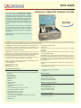
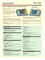
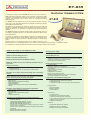
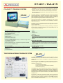
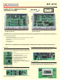
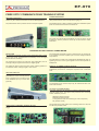
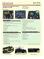
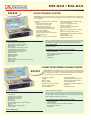
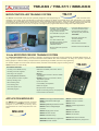
ELECTRONIC TRAINING EQUIPMENT DIGITAL COMMUNICATIONS TRAINING SYSTEM ANALOGUE COMMUNICATIONS TRAINING SYSTEM FIBRE OPTIC COMMUNICATIONS TRAINING SYSTEM COLOUR TV TRAINING SYSTEM VIDEO CASSETE RECORDER TRAINING SYSTEM COMPACT DISK TRAINING SYSTEM RADIO TRAINING SYSTEM CASSETTE RECORDER TRAINING SYSTEM AMPLIFIER TRAINING SYSTEM COMPUTER TRAINING SYSTEM TELEVISION ANTENNA TRAINING SYSTEM (Universal Terrestrial, Cable TV and Satellite Training System) TELEPHONY TRAINING SYSTEM (Analogue & Digital ISDN) MICROPROCESSOR TRAINING SYSTEM MICROCONTROLLER TRAINING SYSTEM APPLICATION MODULES PROGRAMMABLE DEVICES EO-865 For two decades now, PROMAX ELECTRONICA has been designing education related instruments. Over the last few years, we have assigned a laboratory specifically for designing a range of latest-generation educational instruments to help train future professionals in the analysis and repair of communications and consumer electronic instruments, among many others. PERSONAL COMPUTER TRAINING SYSTEM EO-865 Our interests are mainly centred on providing the student with the tools to learn the theory and perform exercises so that he may be capable of localising breakdowns and repair instruments. Below we present a brief list of our Educational range products. The EO-865 is an advanced educational instrument, designed to illustrate the theoretical and practical aspects of the following areas: PC assembly, installation and configuration; hardware architecture and operation and PC testing and diagnosis tasks; allowing, furthermore, the ability to introduce real hardware and software faults and virus for its later elimination. The EO-865 permits the assembly, installation and configuration of all the components composing a multimedia PC of latest generation. It is composed of widely spread and high reliability hardware components manufactured with the latest technology. The EO-865 incorporates a blocks diagram showing the functional modules of a PC. Its multiple Test Points enable the main signals of the PC hardware and its peripherals to be measured, with the aim that the student may establish failure diagnostic and repairing methods. The training system includes software and hardware methods to simulate faults over the different modules of the computer. In order to access and evaluate internal signals, the EO-865 is provided with the requisite hardware and software to: - View POST codes - Show power supply status - Monitor DMA - Monitor interruptions (IRQ) PC Hardware Characteristics: - Intel Pentium® II processor 450 MHz or greater - AMI Atlantis circuit board with AGP port (Advanced Graphics Port) or greater - 32 MB SDRAM - BIOS in flash ROM - 1 AGP slot (64 bits) - 5 PCI slots - 2 ISA slot - 2 USB connectors - 2 Series ports - 1 Infrared (IrDA) series connector - 1 Parallel port - 1 AGP 4 MB video board (64 bits) or greater - 1 Sound board (16 bits)* or greater - 1 Floppy disk drive 3 1/2 1,44 MB - Hard disk drive 4,3 GB or greater - 1 CD-ROM drive, X32 or greater - 1 14'' colour monitor (PHILIPS) Black Matrix 0,28 1024/768 - 1 WIN 98 105 keys - 1 Speaker set* - Detect IRQ and DMA conflicts - Detect resets - Access the ISA bus (board offering the possibility of developing prototypes ) - Test ports The system is designed with the maximum safety measures in order to guarantee student integrity The EO-865 training system comes with the MS-DOS (version 7.0) and the Microsoft Windows 98 Operating Systems on CD-ROM support with an Authenticity Certificate and User's Manual. Also different products are supplied in order the student familiarises himself with PC maintenance tasks: - Diagnostic and repair software to certificate the correct operation of the PC. - Analysis, diagnostic and repair kit (for emergency situations, when it is not possible to boot the PC). - 1 Internal modem of 56k o greater* - 1 Mouse Included software: - Microsoft Windows 98 and MS-DOS operating system - Virus simulation software - Diagnosis and repair software * - Breakdown generation software Diagnosis and Repair Hardware:* - ISA bus analysis and prototype development board - Bus expander board - POST codes detector module - Series port testing module - Parallel port testing modulle Supplied Documentation: - Training System Instructions manual - Technical Documentation EC-796 DIGITAL COMMUNICATIONS TRAINING SYSTEM EC-796 The EC-796 is an ideal equipment for teaching digital transmission systems. It allows to cover the theory and practice of the different stages of a transmission system with ease: sampling, quantification, modulation, simulation of channel and reception; essential to lay the foundations for the modern telecommunication digital network. The Emitter and Receiver modules have a test points prepared for the monitoring of the signals. The EC-796 allows the development of experiments at five levels: - Analysis of the sampling and quantification of analogical signals, with acoustic and visual experimentation of the effect of the sampling frequency (aliasing) and of the number of bits used in the generation of the PCM signal. - Study of digital modulations on continuous wave in amplitude, frequency and phase. - Experimentation of the characteristics of circuit alternatives in the emission and reception modules. Signal inlets and outlets -Inlets for Function Generator, TTL signals and microphone. -Outlet for headphone and connectors for oscilloscope. PCM signal, base band Sampling and quantification: -Clock: 1.333 MHz -T bit: 12 ms -11 bit frame: 1 start, 8 code, 1 stop and 1 parity. -Antialiasing filter BW 3dB: 280-3400 Hz -Compander and expander for microphone. Modulators ASK (OOK) -Bandwidth modulator: DC - 60 kHz. FSK - Band width modulator: DC - 60 kHz (DFD reception) DC - 100 kHz (FSK reception) BPSK and DBPSK - Band width modulator: DC - 45 kHz QAM,QPSK and DQPSK - Bandwidth modulator: DC - 45 kHz - Levels: 8 Demodulators ASK (OOK) Type: Band pass filter, detector of envelope and comparator. FSK Types: - Dual band pass filters - PLL direct detector BPSK and DBPSK Pass band: - Referring to the microphone and signal input: all the antialiasing filter. - Referring to the TTL input: DC - 45 kHz QPSK, DQPSK and QAM (AFK) Pass band: - Referring to the microphone and signal Input: all the antialiasing filter. - Referring to the TTL input: DC - 45 kHz EMITTER CHARACTERISTICS Twin Cable Emitter: Output level (measured at connector): - receiver not connected: 0 at ±4 V (according to modulation) - receiver connected: 0 at ±3 V (according to modulation) Connector: banana female adapter Coaxial Cable Emitter: Output level (measured at connector): - receiver not connected: 0 at ±4 V (according to modulation) - receiver connected: 0 at ±3 V (according to modulation) Connector: BNC female adapter. - Analysis of the effect of disturbance in the channel (interference, noise, bandwidth and attenuation) on the different modulations. - Experimentation on different means of transmission: coaxial cable, two-wire, infrared, radio and optical fibre. The EC-796 is presented in stackable desks, very easy to set up, designed both for graphic demonstrations of the theory explained in class, and for the student to carry out very attractive practices with basic instrumentation. The instruments recommended for operation are a function generator and an oscilloscope. Fibre Optic Emitter: Emission by LED Emission wave-length: 850 nm (red) Infrared Emitter: Emission by LED Emission wave-length: 950 nm 27 MHz Emitter: Output level on 50 W: 10 dBm Antenna: Monopole. 5 mm cable and 150 cm length Connector: BNC female Carrier frequency: 27 MHz (crystal) Modulation on AM: Modulation index of 10 to 40%, according to selected RECEIVER CHARACTERISTICS Twin-Line Cable Receiver:: Type: Direct Connector: Banana adapter Coaxial Cable Receiver: Type: Direct Connector: BNC adapter Fibre Optic Receiver: Type: Photo-diode (PIN). Reception band: 400 - 1,100 nm (for 90% efficiency) FSMA connector Infrared Receiver: Type: Photo-diode (PIN). Reception band: 800 - 1,000 nm (for 50% efficiency) 27 MHz Receiver: Type: Envelope detector Reception band: 27 MHz Antenna: Monopole. 5 mm cable, 150 cm long Connector: BNC female adapter Accessories and documentation included -Antenna connection cables -Optical fibre PMMA with FSMA connectors -Headphone and dynamic microphone -Instruction manual -Theory manual -Practice manual -Electric diagrams and Technical Documentation EC-696 EC-696 ANALOGUE COMMUNICATIONS TRAINING SYSTEM The analogue communications training system EC-696 has several types of emitters, transmission channels, receivers, modulators and demodulators, in order to shape a transmission system easily. For instance, it permits to compare the advantages of several transmission systems to others, including those fibre-optics based, or to analyse interference phenomena. Easy to use and the capability to measure the electrical signals throughout the equipment has been taken into account by means of a series of test points. To this end, circuitry is located into a desk-like cabinet, with a transparent fold-down cover for a complete access. The equipment is composed of one Emitter set and one Receiver set, to be linked during training, by the selected transmission method. EMMITER MODULE EC-696/E The EC-696/E emitting system is provided with several inputs where generators or microphones can be connected. A set of sequential controls allows the equipment to be configured quickly, by selecting the input, modulation (AM, FM, PWM) or transmission modes through five different channels: bifilar, coaxial, fibre-optic, infrared or radio. EC-696/E EMMITER MODULE Signal inputs CO1 and CO2 Maximum level Bandwidth Input impedance MIC1 and MIC2 Sensitivity Input impedance Modulators AM Modulator Carrier frequency Modulation index Bandwidth FM Modulator Carrier frequency Frequency deviation Bandwidth Pulse Modulator (PWM) Carrier frequency Input from a generator ±3V DC to 20 kHz ³ 20 kW (1 kHz) Microphone inputs 6 mVpp, adjustable ³ 20 kW (1 kHz) Voltage-controlled gain amplifier 100 kHz 0 to 100% DC to 20 kHz Voltage-controlled oscillator 100 kHz ± 50 kHz DC to 20 kHz 100 kHz Working range Bandwidth FDM/FM Modulator Carrier frequency Channel bandwidth Emitters Bifilar cable transmitter Maximum level Coaxial cable transmitter Maximum level Fibre optic transmitter Emission Emitting band Infrared ray transmitter Emission Emitting band 27 MHz Emitter Output level Modulation index Antenna 40 to 70% DC to 20 kHz Voltage-controlled oscillator 300 kHz or 100 kHz, selectable DC to 20 kHz Output through operational amplifier ±3V Output through operational amplifier ±3V By LED Photodetector 650 nm (red colour) By LED Photodetector 950 nm 0 dBm 50 % 1.5 m cable Monopole RECEIVER MODULE EC-696/R Signals processed by the EC-696/E can be received and demodulated by the EC-696/R. This system is configured by four pushbuttons and a logic control, the same way as in the emitter. The demodulated and separate signals received can be displayed on the screen of an oscilloscope or monitored by means of earphones. RECEIVER MODULE Receivers Bifilar cable receiver Coaxial cable receiver Fibre optics receiver Type Receiving band Infrared receiver Type Receiving band Radio receiver Peak detector Receiving band Antenna Direct, without processing Direct, without processing (PIN) type Photodiode 400 to 1100 nm (90% efficiency) PIN type photodiode 800 to 1000 nm (50% efficiency) 27 MHz 1.5 m Cable Demodulator specifications AM Demodulator Fast detector Bandwidth DC to 20 kHz (bifilar and coaxial) 300 Hz to 20 kHz (fibre, infrared and radio) FM Demodulator Carrier frequency Bandwidth Pulse demodulator (PWM) Carrier frequency Bandwidth FDM/FM Demodulator Carrier frequency Multiplex bandwidth DPLL type 100 kHz DC to 20 kHz (bifilar and coaxial) Integrator type 100 kHz DC to 20 kHz (bifilar and coaxial) 300 Hz to 20 kHz (fibre, infrared and radio) DPLL type 300 or 100 kHz selectable DC to 20 kHz (bifilar and coaxial) 300 Hz to 20 kHz (fibre, infrared and radio) Output specifications Earphone output Output stage AB Class Volume control Independent for left and right channels Output power 200 mWpp over 32 W (3 Vpp in C) Oscilloscope S1 and S2 outputs Output level ³ 400 m Vpp (3 Vpp in A) ET-835 TELEPHONY TRAINING SYSTEM The telephony training system ET-835 allows the theory and practice of PABX and internal telephone networks to be covered. It incorporates a PABX exchange, internal telephone lines and external lines, charging generator modules, fault simulator and connection points for analogue and digital (ISDN) terminals. ET-835 The ET-835 has block diagrams of each of its constituent modules, and also of its wiring. In the same block diagrams it is possible to measure the signals of the ISDN and analogue lines. The trainer can be connected by modem or directly to a PC from which the operation of the PABX exchange can be managed and configured, in order to initiate the student in the principles of programming of internal telephone networks. The ET-835 simulates the external analogue lines of the exchange, and so it is possible to generate calls from or to the exterior without the need to have actual external lines. It moreover incorporates a pulse generator module which manages the rating of the external calls and in which different situations are simulated which allow the student to observe the effect of defective reception of the charging pulses. Different faults can be simulated either in the PABX exchange, in the transmission lines or in the analogue terminal. The student can thus diagnose and trace faults in a telephone network. It is presented in a casing stackable with the other units of the range in order to aid its storage. GENERAL FEATURES OF THE TRAINING SYSTEM ISDN/ Analogue Telephone Exchange of latest generation Number of external analogue lines: 2 Number of internal analogue lines: 2 Number of internal basic ports So (B+B+D): 4 internal Maximum number of lines: 96 considering both ISDN and analogue lines Telephone terminals: - 1 ISDN terminal with alphanumeric display - 1 analogue terminal - 1 analogue terminal that can be used to simulate failures Simulation of an Urban Telephone Exchange and of the billing circuits Block diagrams with test points and telephone connection points, consisting of the following subsystems: - External Urban Telephone Exchange (2 lines) - Billing circuits - ISDN / Analogue Telephone Exchange - External distributor - Internal distributor - Telephone Terminal that can be used to simulate failures - Wiring Simulation of breakdowns in the following subsystems: - External Urban Telephone Exchange - Billing Circuits - ISDN/ Analogue Telephone Exchange - Wiring - Telephone terminals Composition of the ISDN/ Analogue Telephone Exchange: - Processing Unit (CU) consisting of: - Processor 80C186 - 1 MB Flash EPROM (software memory) - 256 KB RAM Stable (operating memory) - 256 KB Flash EPROM (data memory) - Control unit of communication ESCC2 (Enhanced Serial Communication Controller). - Control of the connection area EPIC (Extended PCM Interface Controller). - DSP (Digital Signal Processor) - Modem, CCITT V21 standard Switching power supply - Primary voltage: 115 V/230 V (configurable), ±10 %, 50/60 Hz Internal ISDN lines unit - 4 basic ports So (CCITT I.430) stimulation mode (B+B+D) - Possible connection to the same basic access of the 2 ISDN terminals with a different consumer's number. - Powering of the terminals (-48 V) External Analogue Lines Unit - 2 analogue lines - Dialling by impulse or multi-frequency - Temporal switching from impulses to multi-frequency - Flash Signals - Control of the loop voltage - Billing at 12 kHz - Call detection at 25/50 Hz - Maximum call voltage 150 Veff - Protection against polarity inversion and overvoltage - Galvanised insulation from the mains Components of the ET-835 Training System - Telephone terminals: - 1 ISDN terminal with alphanumeric display - 1 analogue terminal - 1 analogue terminal that can be used to simulate failures - Documentation: - Instruction Manual - Teacher´s Manual - Practice Manual - Accessories: - 1 mounting pliers - 20 meters of 4-wired telephone cable - 1 cable Exchange-PC (9 pin connector) - 1 cable Training system-Terminal that can be used to simulate failure (25 pin connector) - Telephone Connectors - Software: - Configuration Software (1 diskette) - Software for failures (1 diskette) - Software for Exchange (4 diskettes) ET-891 / EA-815 COLOUR TV TRAINING SYSTEM The ET-891 is an ideal piece of training equipment to teach the operation of colour TV receivers, which allows the student to familiarise himself with the most advanced technological innovations. The tutor includes a fault generation module and a trainer for the I2C communications Bus. ET-891 The block diagrams of the ET-891 intuitively shows the different modules which make up the colour TV receiver. Its over 50 test points allow the analysis and monitoring of the electric signals in the different functional blocks of the receiver. It is safe to operate since all the test points are protected against possible accidental short-circuits. Using the fault module it is possible to simulate the most common faults which can occur in the receiver with thus establishing methods of diagnosis and tracing. The trainer moreover incorporates a microcontroller which makes2 it possible to carry out practices related to the operation of the I C communications BUS. Special attention has been paid to its design, obtaining a small-sized functional piece of equipment. Moreover, in its rest position, it can be used as a domestic desktop TV. COLOUR TV RECEIVER - 14" screen PAL B/G/I and SECAM B/G/L/L systems. NTSC M (ET-891/1 Option) - Euroconnector * - Stereophonic sound and dual system* - Zweiton system* - NICAM audio digital system* - Teletext with FLOF function * - On screen messages (OSD) - Tuning by synthesis of manual voltage or autostore through search and automatic memorisation - Infrared remote control - Advanced hybrid technology: conventional components and SMD * Not available with ET-891/1 Option BLOCK DIAGRAMS The block diagrams are composed of the following functional modules: - Power supply - IF and demodulator - Video - Sound - Microcontroller - Teletext - Deflection FAULT SIMULATOR A set of 48 microswitches allows over 35 faults to be provoked. These have been divided into the different functional stages of the receiver. TUTOR FOR THE I2C BUS A set of microswitches allows the start and stop bits to be modified, in addition to the words of the data which are sent to the integrated circuits connected. The words received by the ICs are displayed by a series of LEDs. DOCUMENTATION INCLUDED - Instruction Manual - Practice Manual - Technical Documentation Manual TELEVISION ANTENNA TRAINING SYSTEM EA-815 The EA-815 Universal Antenna trainer for MATV (Master Antenna Television), SMATV (Satellite Master Antenna Television) and CATV (Cable Television) system is designed for study and training on installations The main purpose of the EA-815 is to enable the student to calculate, install, configure, adjust, alter, analyse and localise breakdowns in distribution networks using: - Terrestrial television (MATV) - Analogue and digital satellite television (SMATV) - Cable television (CATV). The EA-815 trainer offers a flexibility which enables an endless number of real MATV, SMATV (analogue and digital) and CATV installations to be reproduced. It is possible to recreate the more common breakdowns and problems the student will come across on the field. It allows him furthermore to test and compare the efficiency of the different solutions available to him. The student will be able to familiarise himself with the professional equipment used in real installations and advanced instruments such as field strength meters, spectrum analysers or the ST-240 (included). This is a satellite band signal generator, used in testing satellite receivers and external units or LNBs. EA-815 TELEVISION ANTENNA TRAINING SYSTEM EA-815 The work book presents practical exercises designed to facilitate the learning process. The proposed exercises have the aim of calculating and performing measurements on different types of installations and localising the more common problems which the student will come across in future installations. The trainer components are laid out on an erasable board, which allows the teacher to draw the configuration of the reception, amplification and distribution system the student has to set up. This diagram will be used by the student as a guide and from it he can easily assemble the installation. The white board may be used as a note pad by the student to write down the measurements taken beside each component when analysing an installation or trying to localise a breakdown, so that he can immediately determine the attenuation of the each section of the installation. ANTENNAS - 27 element UHF antenna (channels 21-69) - 90 cm centred focus parabolic antenna containing: - Reflector - Double LNB (H and V) (power adapter included) - Accessories: rods and power accessories MECHANICAL ACCESSORIES - 150 cm mast for terrestrial antenna - 80 cm mast for parabolic antenna - Mobile stand for antennas with wheels PARABOLIC ANTENNA MOTOR - Motorised arm for aiming parabolic antenna HEAD END EQUIPMENT- MATV - MATV - Set of 8 programmable UHF amplifiers - VHF amplifier - Power supply - SMATV (analogue and digital) for RF - Programmable IF-UHF (stereo) internal units - Universal programmer - Power supply for internal units - SMATV (analogue and digital) for IF - Adjustable IF amplifiers (x4) with terrestrial signal mixing and amplification - Power supplies for LNBs and IF amplifiers COLLECTIVE AND INDIVIDUAL MATV DISTRIBUTION COLLECTIVE AND INDIVIDUAL SMATV DISTRIBUTION (ANALOGUE AND DIGITAL) BY INTERMEDIATE FREQUENCY - Splitters/combiners - Taps - Through outlets and end outlets - Splitter outlets - IF splitters - H and V commutable IF splitters - IF outlets COLLECTIVE AND INDIVIDUAL SMATV DISTRIBUTION (ANALOGUE AND DIGITAL) BY CHANNEL PROCESSING MIXED COLLECTIVE AND INDIVIDUAL SMATV DISTRIBUTION COLLECTIVE CATV DISTRIBUTION - CATV line amplifier with attenuator, equaliser and pre-emphasiser - Active return channel with gain control USER EQUIPMENT - Tuner-receiver and antenna positioner - Remote control MINI-SATELLITE AND RECEIVER AND LNB TESTER - ST-240 ACCESSORIES FOR AIMING ANTENNAS - Inclinometer - Compass ACCESSORIES AND CABLES - Roll of coaxial cable - 6-conductor cable - Markers for the white board OTHER ACCESSORIES - Load adapters - Bridges - Polarising connector DOCUMENTATION - Instruction Manual - Practice Manual - Technical documentation - Assembly instructions EF-970 FIBRE OPTIC COMMUNICATIONS TRAINING SYSTEM TRANSMITTER MODULE EF-970 CLASS 1 LASER PRODUCT RECEIVER MODULE The EF-970 trainer is an innovative system designed for training, demonstration and experimentation with the Fibre Optics communication systems, the phenomenon related to light and the principles of transmission through Optical Fibres; as well as the latest tendencies like LASER and WDM ( wavelength multiplexing). The equipment consists of: - Emitter module, two independent channels with photo-emitters and LASER - Receptor module with optical power measurements. - Accessories. - A set of Optic Fibres - Documentation. EMITTER KIT, CONSISTING OF TWO INDEPENDENT CHANNELS WITH LED AND LASER-PHOTOEMITTERS BF GENERATOR (SQUARE, TRIANGULAR, SINUSOIDAL) 8 INPUTS The instrument possesses eight selectionable inputs. The input signal may be selected, either channel 1 (CH 1) or channel 2 (CH 2), the same input may also be used for both channels. 1- BF generator: sinusoidal, triangular or square (internal) signal 2- DC analogue input (75 W) (external) 3- AC analogue input (75 W) (external) 4- Microphone (monophonic) (external) 5- Digital input (External) 6- Inverted digital input (External) 7- Digital input permanently on "1" (internal) 8- Digital switch "1" / "0", using the TL1 key (internal) CHANNEL 1 AND 2 The emitter kit consists of 2 independent channels (channel 1 and channel 2) that enable signals to be transmitted from any optical input and control the amplification of the input signal level. Includes channel overload or saturation indicator. The BF generator possesses four control buttons to select the wave form (square, triangular or sinusoidal) and the frequency MILLIAMMETER The emitter kit consists of a digital milliammeter showing the polarisation current flowing through the chosen photoemitter. The channel to be measured is selected with the "A METER CH1/CH2" button. EF-970 FIBRE OPTIC COMMUNICATIONS TRAINING SYSTEM OPTICAL OUTPUTS LASER FEEDBACK The emitter kit has six cyclically selectable photoemitters. Two photoemitters may be activated at the same time for the WDM application. The nature of the LASER means that its optical power may be influenced by external factors such as temperature, ageing, etc. The photoemitters have a protection circuit to limit optical power. The feedback circuit is able to maintain a stable and unalterable optical power no matter what the external conditions are The system can operate with the feedback circuit On or OFF so to test its efficiency and the problems caused by its disconnection and/or malfunction RECEIVER KIT WITH OPTICAL POWER METER RECEIVER The receiver kit principally consists of two independent blocks (except for the input circuits: photodetectors and switches), one for the signal and the other for measuring. The signal block contains two channels, also independent, one for receiving analogue signals and the other for digital signals. The measuring block contains the power meter, enabling operation in four different modes: analogue, digital, 1 kHz and DC. The signal block possesses a switch to select the type of coupling, DC or AC, applied to the first amplifier input and to the analogue channel output section. The audio section consists of an independently-adjustable low-pass for regulating the level of the signal applied to the internal speaker or headphones. DIGITAL CHANNEL SIGNAL BLOCK The signal entering the digital channel follows a series of filtering and amplification processes for subsequent comparison with a reference level. OPTICAL INPUTS The receiver has four incorporated photodetectors and an external photodetector (optional) that connects to the "EXT. SENSOR" input by a coaxial cable (optional). The amplitude of the channel output may be selected as either TTL level or RS-232 level. OPTICAL POWER METER This block performs the absolute or relative measurement of the received optical power. The optical meter possesses four measuring modes, selected by the user ANALOG (monitoring mode) DIGITAL (monitoring mode) 1 kHz (precision mode, for measuring the 1 kHz component) DC (precision mode) ANALOGUE CHANNEL SIGNAL BLOCK The analogue channel has a gain of 40 dB, using two 20 dB amplifier stages. The resolution of the power meter in the monitoring modes is 0.1 dB, and 0.01 dB in the precision modes. EF-970 FIBRE OPTIC COMMUNICATIONS TRAINING SYSTEM EF-970 OPT -970-01 INCLUDED ACCESSORIES - 1 variable attenuator - 3 ST adapters for the photodetectors - 1 ST adapter for 650 nm filter photodetectors - Cleaning components:: - 1 ST adapter for 850 nm filter photodetectors - 1 box with anti-static cleaning cloths - 1 shutter (diaphragm) - 1 isopropyl alcohol container (the isopropyl alcohol is not supplied) - 1 reflection sensor - 3, 1 m pieces of optical fibre - 1, 1 m piece of optical fibre without protective covering - 1, 50 m optical fibre - 1 reflecting lamina - 1 U-sensor - 1 liquid container - 1 external photodetector (1 mm Si PIN) - 2 ST-ST adapters - 1 measurement adapter (for external photodetector) - 1 magnifying lens - 1 shielded connector cable for external photodetector - 1 microphone - 1 screwdriver - 1 headphones OPT-970-01 OPTIONAL ACCESSORIES: EXERCISES KIT OPT-970-02 OPTIONAL ACCESSORIES: CONNECTION KIT - 1, 2 m piece of optical fibre - 1 tool for removing the protective covering from optical fibre - 1, 2 m piece of optical fibre without protective covering - 1 set of modal filters (cylindrical hoops with various radiuses) - 2 clips for modal filters - 1 set of plaques for generating high-density microcurves - 1 set of plaques for generating low-density microcurves - 1 optical fibre arm - 1 ST crimping tool - 1 polishing disk - 1 set of abrasive laminas - 1 elastic polishing pad - 1 rigid pad - 1 liquid container - 1, 10 m optical fibre cable - 2 fixed WDM devices - 10 ST connectors - 1 variable WDM device - 1 white light source (powered by two LR03 1.5 V alkaline batteries, not supplied) - 1 set of neutral optical filters - 1 universal bracket (No 1) Composition and quantities subject to variation - 1 universal bracket (No 2) OPTICAL FIBRE ARM VARIABLE OPTICAL ATTENUATOR VARIABLE WDM DEVICE EF-970 FIBRE OPTIC COMMUNICATIONS TRAINING SYSTEM EMITTER MODULE The emitter kit for the simultaneous transmission of two independent channels of up to 10 MHz consists of the following blocks: EF-970 - WDM system multiplexer-demultiplexer - Device for creating microcurvatures in optical fibres - Connector tools SUPPLIED DOCUMENTATION Inputs - Analogue (separate DC and AC) - Functions generator (internal) - Microphone - Digital (with possibility of inversion) Emitter stage - Channel 1 - Channel 2, with actionable laser feedback Amperimeter, for adjusting photoemitter polarisation current Photoemmitters - 526 nm Led - 590 nm Led - 660 nm Led - 850 nm Led - 1300 nm Led - 650 nm Laser Fault simulator RECEIVER MODULE Photoreceptors - 1 mm Si PIN - 1 mm InGaAs PIN - 0.1 mm Ge APD (variable internal gain photodetector) - 2.5 mm Si PIN - 1 mm Si PIN (included with the optional OPT-970-01 Optical Fibre Experiment Kit) Precision measurement channels - 1 kHz, to prevent influence from external optical sources - Very low DC noise, for very precise measurements Receptor stages (with variable inverse polarisation) - Analogue channel - Digital channel Optical power meter (dBm and mW) with absolute and relative mea surements Outputs - Analogue (high or low impedance) - Digital (TTL or RS-232) - Speaker (internal) and headphones Fault simulator OPTICAL FIBRE AND OPTIONAL ACCESSORIES - Optical fibre arm - Variable optical attenuator - Instruction Manual - Practice Manual PARTIAL LIST OF EXERCISES - Measuring optical power - Measuring the attenuation of an optical fibre - Insertion losses method - Measuring the attenuation of an optical fibre - Spectral dependence of the attenuation of an optical fibre - Influence of ambient light - Connecting optical fibre using ST-ST adapters. - Measuring repeatability - Measuring the P/I characteristics of photoemitters - Measuring the optical stability of photoemitters - Measuring the V/I characteristics of photoemitters - Frequency characteristics of photoemitter modulation - Spectral dependence of photodetectors - Inverse voltage in photodetectors - Bandwidth of photodetectors - Transmission of analogue signals - Transmission of audio signals - Transmission of video signals - Transmission of digital signals - RS-232 transmission by optical fibres - Sensitivity of optical fibre to curvature (Macrocurves) - Radiation characteristics of optical fibre - Measuring numeric aperture - Measuring sliding in optical fibre connections - Characteristics of a fixed WDM device - Characteristics of a variable WDM device - Measurements with neutral optical fibres - Measuring insertion loss by the variable optical attenuator - Comparing noise characteristics between PIN and APD photodetectors - WDM: multiplexation and demultiplexation - WDM system - WDM transmission - Transmission sensor - Reflection sensor - Liquid level sensor - Liquid presence transmission sensor - Connections with the optical fibre connector tool kit The trainer may be extended with the OPT-970-01 Optical Fibre Experiment Kit and the OPT-970-02 Connector Kit. ED-823 COMPACT DISC TRAINING SYSTEM The ED-823 Compact Disc Player Trainer is an educational device for the theoretical and practical study of the digital audio in CD format. Its functional structure enables the user to view the movements of the mechanical elements and to analyse the electrical signals of the various functional modules that comprise the player system. Furthermore, the instrument includes a malfunction simulator for the study of troubleshooting and diagnostic methods. The E D - 8 2 3 is equipped with a player of high-level features, which is widespread on both the professional and domestic markets, it is considered a leading-edge instrument. The ED-823 trainer is built into a console-type cabinet which incorporates a compact disc player. Beneath the top cover of the trainer there is a panel that shows the block diagram of the sound reproduction system, the servosystems, the signal processing, the pickup, the audio, and the power supply. Many test points have been inserted in the block diagram for the purpose of analysing the electrical signals that are involved in its functioning. In addition, the ED-823 includes new concepts such as the possibility of making repairs and adjustments using remote control and the keyboard. ED-823 The malfunction simulator is operated by activating the microswitches, protected by key, which can generate multiple failures in the various modules of the device. TEST DISCS FOR DIGITAL PLAYERS (C.D.) A set of two test discs for the adjustment and checking of compact disk players. DISC I This disc has 56 tracks with audio information of different frequency, level, with and without pre-emphasis; as well as other tracks to analyse the circuits from the A/D converter to the low frequency output stage. DISC II This disc has 50 tracks with information for the testing and adjustment of the servos. It has tracking and velocity errors; errors in the length of the pits and signal drop-outs, which make it very easy to check and adjust the circuits. LASER - Fixed laser mechanism - Semiconductor (l=780 nm) - Duration of the emission: continuous 44.6 mW FREQUENCY RESPONSE - From 2 Hz to 20 kHz ± 0.5 dB SIGNAL TO NOISE RATIO - More than 102 dB DYNAMIC RANGE - More than 98 dB HARMONIC DISTORTION - Less than 0.0035 % CHANNEL SEPARATION - More than 100 dB OUTPUTS - Line Out (maximum level output 2 V at 50 kW) - Digital Out (optical output, maximum level -18 dBm) - Headphones (maximum level output 10mW at 32 W) VOLUME CONTROL OUTPUTS - Up to -20 dB REMOTE CONTROL - Infrared remote control ADVANCED FUNCTIONS - Shuffle - Repetition - Musical calendar - Music Scan - Own program creation - Synchronised editing - Fader (gradual appearance and disappearance of sound - Automatic introduction of spaces BLOCK DIAGRAMS The block diagrams consist of the following functional modules, each of which has points for testing the most important signals involved in their functioning - Pickup block - Drivers - RF amplification - Servosystems - Digital processing - System Control - Keyboard, remote control, display - Power supply - Audio Furthermore, the current of the laser diode can be measured on the block diagram. MALFUNCTION SIMULATOR The malfunction simulator manipulates the electrical points of the compact disk player and can simulate thirty real failures. ACCESORIES AND DOCUMENTATION INCLUDED - Instruction Manual - Practice Manual - Electric diagrams and Technical Documentation - Set of transparencies - Test Disc - Amplified speakers (self powered) - Leads and batteries (remote control) EV-830 / EP-834 VIDEO CASSETE RECORDER TRAINING SYSTEM The EV-830 video trainer is a teaching equipment intended for training Professional students in an easy and enjoyable manner, which makes them possible to assimilate the operation and the repair techniques of VHS video equipment. It is accompanied by extensive documentation which includes theory, practices, mechanical and faults manuals. The EV-830 has been designed on a multifunctional support which aids the analysis of the most important electric signals in the different modes of operation of the video, the inspection of all the movements of the mechanical elements, including the mechanical parts normally hidden by the video tape, and the simulation of the most frequent faults. Under the upper cover of the equipment, there are block diagrams of the video with over 50 test points, which allow the visualisation and monitoring of the different electric signals in any mode of operation. All the test points are protected against possible accidental short-circuits. EV-830 The units can be stacked with the rest of the range and in their rest position they can be used as domestic desktop apparatus. VIDEO RECORDER-PLAYER The EV-830 incorporates a video recorder manufactured with the most advanced technology, equipped with a high level of features and with a wide diffusion on the market. From among its characteristics we can highlight: - PAL system - Automatic tuning - Two heads - Self-cleaning - Auto-tracking digital - 2 Euroconnectors - Frame-by-frame and pause - Electronic blocking - Automatic System for failure detection BLOCK DIAGRAMS The block diagrams consist of the following functional modules, each with the test points of the most important electric signals involved in its operation: AMPLIFIER TRAINING SYSTEM EP-834 - Tuning - Video - Sound - Servosystems - Control System - Power supply FAULT SIMULATOR The fault simulator manipulates electric points of the video, allowing over 35 real faults to be simulated. ACCESSORIES AND DOCUMENTATION INCLUDED - Instruction Manual - Practice Manual - Electric diagrams and Technical Documentation - Set of transparencies - Video Pattern tape: TM-4 - Video tape in transparent casing:TM-5 The EP-834 has been designed from a high end power amplifier equipped with the most advanced technology and design. From among its characteristics we can highlight: - DIN power output (4W at 1 kHz): 70 W + 70 W - Protection against short circuits - Tone control: bass and treble - Loudness control - Balance adjustment - Subsonic filter - 6 audio inputs - Source Direct (to listen directly to the input signal) - Tape monitor - EON-LINK connection (switch to EON programme with RDS broadcast stations) BLOCK DIAGRAMS The block diagrams consist of the following functional modules: Input signal source - Input signal source control - Equalisers - Loudness filter - Power section - Speakers protections - System control - Power supply Each one of the functional sections have several test points which permit the analysis and monitoring of the main electrical signals of the amplifier. Safe to operate, all the test points are protected against possible accidental short-circuits. - Headphone output - Non-vibration chassis - Total harmonic distortion: less than 0.008% (at 10 W output) - Frequency response: - PHONO (20 Hz - 20 kHz): RIAA equalisation curve ± 0.5 dB - TUNER, CD, AUX, TAPE1/DAT, TAPE2/MD: 7 Hz - 70 kHz ± 0.3 dB - S/N ratio - PHONO: 80 dB - TUNER, CD, AUX, TAPE1/DAT, TAPE2/MD:105 dB FAULT SIMULATOR The fault simulator manipulates electric points of the amplifier, allowing to simulate a large number of real faults. ACCESSORIES AND DOCUMENTATION INCLUDED - Instruction Manual - Practice Manual - Electric diagrams and Technical Documentation - Speakers - loads - Remote control ER-832 / EG-833 ER-832 RADIO TRAINING SYSTEM The ER-832 has been designed from a stereo radio tuner equipped with the Radio Data System (RDS) and with the most advanced reception circuits. From among its characteristics we can highlight: - Radio Data System (RDS). Incorporated functions: - Name of the broadcast station - Traffic Announcements (TA) - Alternative Frequency (AF) - Automatic switch to stations which transmit traffic information, news or informative programs. - Current Time display (CT) - Broadcast station search according to program type (PTY) - Radiotext - Display of emergency announcements. - Digital signal level meter (display range from 16 to 70 dBmV) - Frequency range (FM, MW, LW) - FM: 87.5 108 MHz - AM: 522-1611 kHz, 144-288 kHz - 30 pre-set memories - Direct tuning through frequency introduction - Automatic broadcast station search - Automatic alphabetical ordering of the broadcast stations - Menu selection system - Display personalization Each one of the functional sections has several test points which permit the analysis and monitoring of the main electrical signals of the tuner. All the test points are protected against possible accidental short-circuits. BLOCK DIAGRAMS The block diagrams consist of the following functional modules: - AM radio-frequency input section - AM intermediate frequency amplifier - AM oscillator and mixer section - AM detection - PLL synthesiser and frequency divider - FM radio-frequency input section - FM intermediate frequency amplifier - FM oscillator and mixer section - FM demodulator - Multiplex decoder - RDS demodulator - Output section - System control - Automatic tuning system and memories section - Audio section - Power supply FAULT SIMULATOR The fault simulator manipulates electric points of the tuner, allowing to simulate real faults.. ACCESSORIES AND DOCUMENTATION INCLUDED - Instruction Manual - Electric diagrams and Technical Documentation - Auto-amplified speakers - AM Antenna - FM Antenna CASSETTE RECORDER TRAINING SYSTEM The EG-833 has been designed from a stereo cassette deck equipped with DOLBY B and C noise reduction systems and with the new circuit HX-PRO which adapts the recording to the appropriate modulation level automatically. From among its characteristics we can highlight: EG-833 - 2 Super density heads - 2 Motors - Dolby©B and C - Dolby HX-PRO© - Automatic Tape Selector (ATS) - Ceramic cassette holder - Cassette stabiliser BLOCK DIAGRAMS The block diagrams consist of the following functional modules: - Input section - Recording process section - Playback process section - Oscillator and erase head - HX-PRO © - Output section - Noise reduction systems: Dolby© B and C - System control - Servos - Automatic Music Search (AMS) - Power supply FAULT SIMULATOR The fault simulator manipulates electric points of the cassette deck, - Signal level indicator - Automatic calibration of the bias level - Automatic Music Search (AMS) - Selectable MPX filter - Controlled from SONY amplifiers or receivers - Headphones output allowing to simulate real faults. Each one of the functional sections has several test points which permit the analysis and monitoring of the main electrical signals of the cassette deck. It is safe to operate, all the test points are protected against possible accidental short-circuits. ACCESSORIES AND DOCUMENTATION INCLUDED - Instruction Manual - Practice Manual - Electric diagrams and Technical Documentation - Auto-amplified speakers - Test Tape TM-683 / TM-311 / MM-6XX MICROCONTROLLER TRAINING SYSTEM TM-311 The TM-311 microcontroller trainer has been specifically designed to teach programming and use of the most commonly used commercial microcontrollers on the market, quickly and efficiently.The instrument is based on the 80537 microcontroller whose main characteristic is its complete compatibility with the 8031/8051 range of microcontrollers, widely distributed throughout industry. This is the basic starting point for training future microcontroller experts. Furthermore, the 80537 being a much more up-to-date microcontroller, it includes a multitude of improvements that make it more powerful and easier to use, such as: 9 I/O ports, 12 analogue inputs, programmable reference voltage and multiple data pointers. - Equipped with a 80537 microcontroller, 100% compatible with software for the 8031/8051 range of microcontrollers. - 32 k EPROM for program code. - 32 k static RAM for program code. - Connector allowing access to the microcontroller I/O ports - Communication with PCs by RS-232C (2 ports) or RS-485 FEATURES - Assembler, diagnosis and simulator software - 32 k static RAM for data. - Application connector compatible with MM-6XX series PROMAX modules. - Microcontroller bus expansion connector - RS-232C cable - Technical Documentation - Software and exercise Manual 16 bits MICROPROCESSOR TRAINING SYSTEM The TM-683 MICROINSTRUCTOR is intended for developing and debugging application programs related with the 68000 Microprocessor, by using a personal computer or a terminal as control elements. Definite features have been considered in its design so to produce a prominent training equipment in fields covered by microprocessors and, specifically by the 68000, its structure and programming. The software supplied is a three-module structure: Monitor, Simulator and Assembler programs. Working with the TM-683 is efficient and user-friendly. SOFTWARE FEATURES HARDWARE FEATURES - Handling of the TM-683 memory - CPU Uses the 68000 mP at 8 MHz without wait states - Handling of the CPU registers - Executing a user program - File handling (Motorola S28 format) - Further specific functions of system - Memory handling menu - Block handling menu - Port handling menu - Execution options menu - Assembler program TM-683 - Memory Provided with 64 k words of 16 bits in SRAM (128 kbytes) - EPROM memory for 32 k words of 16 bits, expandable up to 64k - Inputs and outputs - Connectability and expansion - 68000 own signals - Microprocessor control signal - Signals for decoding memory and peripherals - Communication with terminal APPLICATION MODULES MM-600 Power Supply for MM-6XX Modules MM-610 Universal Controller The MM-6XX family modules have been conceived as extensions to PROMAX micro-instructors, designed to make using and learning about microprocessors as control components that much easier. MM-601 Crossroad with Traffic Lights Simulator MM-612 Centronics Interface MM-602 Digital/Analogue Double Converter MM-6XX MM-603 8 Channel Analogue/Digital Converter MM-604 Stepping Motor Control MM-605 DC Motor Control MM-606 Solid-State Relays MM-607B EPROM Memory Programmer MM-608B RS-232C Interface MM-613 Printer MM-614 Hardware Applications Extension MM-615 MODEM MM-616 Audio Module MM-617 Lift Simulator MM-619 Basic Exercise Module MM-620 EPROM Memory Programmer TM-530 APPLICATION PROGRAMMING AND DEVELOPMENT TRAINER WITH PROGRAMMABLE LOGIC DEVICES The TM-530 trainer is an innovative educational tool specifically created for easily learning the design, programming and development of applications using programmable logic devices (PLD). It may also be used professionally as an agile testing instrument for designing logic circuits without the need of creating connections or welding, or wasting time building circuits. TM-530 The instrument consists of: - Wiring configuration and programming software - PLD application design, compilation and simulation software - Hardware module + ISP devices (in system programmable) - Documentation The configuration software enables PLD connections to be graphically assigned to the various components that make up the hardware module, without the need of the student to physically having to create the connections. The same software loads the application files (previously generated by the design software) onto the hardware module ISP device, "in system programmable". devices (ispGAL22V10 and ispLSI1024), null insertion socket for GAL devices and a wide range of inputs/outputs (micro-switches, buttons, clocks, LEDs, displays and A/D and D/A converters, etc.) assigned by the configuration software. It also has a parallel bus output that is compatible with MM-6XX series Promax modules. Using the PLD application design, compilation and simulation software, the student enters the logic circuit design with diagrams or ABEL-HDL to generate the JEDEC file, which is then recorded in the PLD. Operation of the design may be functionally simulated before recording. The hardware module is then used by the student to test the real operation of the application. The hardware module includes two Lattice Documentation consists of an Instructions Manual, a Theory Manual* and an advisory Exercise Manual. Programming GAL-type logic devices: 16V8, 20V8 and 22V10 Null insertion sockets for PLDs Programming ispGAL22V10 and ispLSI1024 logic devices on boards. Trainer board for testing applications Flexible input/output software assignation of the logic device according to application Available inputs/outputs: - 1, 8-bit D/A converter - 1, 8-channel, 8-bit A/D converter - 2, 7-segment displays - 2 relay outputs - 16 switches - 1 variable oscillator - 16 led diodes - 2 buttons - 1 hexadecimal keyboard - 1 application connector Output compatible with PROMAX series MM-6XX educational modules Communication between the trainer/programmer and a PC using the RS-232 port Exercises (extract):: - Basic gates: NOT, AND, OR, NAND, NOR, XOR, NXOR - Multiplexer/ Demultiplexer - Encoder/Decoder - bit adder 4, 8, ... - Comparator - Counter - Sequence detector - Multiplier - Chronometer - Keyboard - A/D conversion - D/A conversion - Adding/subtracting analogue signals - Multimeter with 7-segment display - Function generator - High-pass and low-pass digital filters - Traffic simulator 1 - Lift1 - Audio amplifier 1 - Stepping motor control 1 - DC motor control 1 Requirements: - PC-486 or greater - Windows 3.1x or Windows 9x platform 1With MM-6xx modules Included power supply PROMAX ELECTRONICA, S.A. Francesc Moragas, 71 * Apartado 118 * 08907 L'HOSPITALET DE LLOBREGAT * SPAIN Tel: 93 260 20 00 * Tel Intl: (+34) 93 260 20 02 * Fax: 93 338 11 26 * Fax intl: (+34) 93 338 11 26 * http://www.promax.es * E-mail:[email protected] 0 IP4557 The design and specifications of all the instruments are subject to changes without prior warning CHARACTERISTICS Agreeable working conditions *To be published soon