1
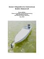
Sensor Integration for Autonomous
Robotic Watercraft
Bruce White
Master of Science in Electrical Engineering
Applied Research Project
San Francisco State University
May 2006
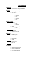
Table of Contents
1. Background
•
General Description of Autonomous Operations
•
General Description of Project
2. Logistics
•
•
•
Navigation System Description
Lake Bottom Depth
Water Quality
•
Humminbird Matrix 55
o
Capabilities
o
Power
o
Communication
Hach Environmental MiniSonde MS 4a
o
Capabilities
o
Power
o
Communication
3. Sensors
•
4. Sensor Computer
•
Hardware
o
o
o
o
o
•
Software
o
o
o
Microcontroller
Power
Main board
Interface Board
Boat Mounting
Depth
Water Quality
Data Transfer
5. Troubleshooting
•
System Clock
•
Stop Bits & Frame Length
•
Initial Byte Capture
6. Operation
•
•
•
Lake Bottom Depth
Water Quality
Data Transfer
7. Results
•
•
•
8. Conclusion
•
•
Boat Route
Result Reliability
Anomaly
Lessons Learned
Future Work
9. References
10. Appendix
•
•
•
•
•
•
•
Test Run Examples
ATmega32 C Code
Initialization Program Flowchart
Interrupt Program Flowchart
Sonde Program Flowchart
Matrix Program Flowchart
Sensor Computer Schematic
2
1. Background
In today’s world, many tasks considered dull, dirty, or dangerous are
increasingly performed by robotic and autonomous systems. Such is
the case with the collection of scientific data. Exhibiting superior
efficiency, precision, reliability and repeatability, autonomous systems
allow measurement without human oversight or intervention. This
streamlines the scientific process, allowing resources once required for
data collection to be reallocated to data analysis, facilitating faster
interpretation and hastening breakthroughs.
The goal of this project was to investigate sensor integration
possibilities for an autonomous boat created in the San Francisco State
University Autonomous Vehicle Lab1. Built by Mechanical & Electrical
Engineering students and overseen by Dr Michael Holden, PhD,
Assistant Professor of Mechanical Engineering, the boat was intended
for use by students in San Francisco State’s Civil Engineering program
to autonomously describe lake bottom contours and monitor water
quality in Lake Merced1, a reservoir in San Francisco.
2. Logistics
The boat was to be driven by a navigation computer attached to a
Global Positioning System (GPS)2. The minutia of this system will not
be discussed here, but a brief overview is necessary for full
comprehension of navigation and sensor system linkages. A
predetermined course would be entered into the navigation computer
with specific waypoints along the route2, and the boat would be placed
in the water and activated. The navigation computer would then use
the real-time data from the GPS to determine the boat’s current
location, and steer and throttle accordingly to reach the next
waypoint2. These waypoints would be ideal locations to take sensor
readings, as any data would be meaningless without an associated
location.
The purpose of the boat was to describe lake bottom contours and
monitor water quality, and each of these tasks would require its own
dedicated sensor. In the early planning stages it was noted that the
water quality sensor likely to be used would be bulky and require a
deeper submersion than the hull of the boat itself, whereas the depth
sensor would not have the same constraints. As such, it was decided
the boat would set out initially with only the depth sensor. One course
3
would be completed by the boat, with a depth measurement taken at
each waypoint along the route.
Once the course was completed, the boat would return to shore and
the sensor computer would be connected to a laptop for transfer of
depth results. Based on this, the water quality sensor tow cable length
would then be changed to prevent the sensor from being accidentally
dragged on the bottom of the lake and damaged. Assuming a safe
depth at each waypoint, the boat would then be sent back out with
only the water quality sensor, to repeat the same course. Upon
completion of the course, the boat would return to shore and the
results would be transferred to the laptop for later analysis.
3. Sensors
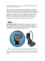
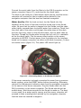
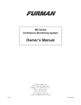
Lake Bottom Depth: To map lake bottom contours, a depth sensor
was required. Humminbird fish finders was contacted, and they
graciously donated one of their Matrix 55 depth finders. To detect lake
bottom depth, the Matrix uses a transom-mount sonar transducer
coupled with a transceiver/central processing unit.
Figure 1 – Humminbird Matrix 55 Transceiver and Sonar Transducer3
Between 10-20Vdc is required to power the sensor4, and as such it had
to be wired directly to the boat power supply, a 12V sealed lead-acid
battery.
4
The Matrix transducer is connected to a transceiver, which performs
analog-to-digital conversion of the sonar signal. Digital data are sent
from the transceiver via RS-232 serial communication protocol at 4800
baud, 8 data bits, no parity, and 1 stop bit5. Only a passive mode of
operation is available, so the Matrix cannot be externally triggered to
take a reading. A string of 8-bit ASCII characters is output once per
second from the device, each “sentence” adhering to the NMEA 0183
standard5, and reading the data is a matter of recognizing and storing
the desired parameters within the string. The depth reading is output
only in meters.
Water Quality: To adequately monitor water quality, the obvious first
choice of instrument was an integrated device with multiple sensors.
Selection was left to students in the San Francisco State University
Civil Engineering Department, who would be doing the analysis of any
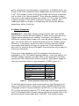
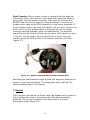
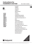
water quality data. The final choice was the Hach Hydrolab MS4a
MiniSonde. Measuring water temperature [C, F, K], pH [pH Units],
sensor depth [m, f, psi], dissolved oxygen [%sat, mg/L], and specific
conductivity [mS, µS]6, it was an appropriate choice.
Figure 2 – Hach Hydrolab MS4a MiniSonde7
The Sonde runs on 12Vdc supplied by 8 internal AA batteries6. This
simplified power requirements for the boat, as it was not necessary to
connect the instrument to the boat’s internal battery.
The Sonde communicates digitally via RS-232 serial communication
protocol at 9600 baud, 8 data bits, even parity, and 1 stop bit8. It
features Modbus 3 and TTY modes of operation8 that allow for both
5
active and passive communication, respectively. In Modbus mode, the
Sonde is idle until a specific 8-byte hexadecimal string is sent to wake
it up8. Once awake, further 8-byte hex strings can be sent to activate
one or more of its internal sensors8. Once a sensor reading is taken,
the result is returned as a 9-byte hex string8. In TTY mode, the Sonde
outputs a string of 8-bit ASCII characters once per second6, and
reading the data is a matter of recognizing and storing the desired
parameters within the string.
4. Sensor Computer
Hardware: To take water-quality measurements, the most flexible
option was to use the Sonde’s Modbus 3 mode, which required active
triggering and detection of a reading. Conversely, the Matrix’s
effectively constant data stream only required passive detection. Either
way, the results had to be received and stored by an outside system.
Moreover, a low-power, small-form factor solution was also desired
since space and battery life were at a premium. These constraints
were met by using an Atmel ATmega32 microcontroller as the heart of
the sensor computer.
Power to all boat hardware, with the exception of the Sonde, is
provided by a 12V 7Ah sealed lead-acid battery. From this battery, an
LM7805 voltage regulator provides 5Vdc to the Atmega32 and other
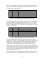
peripherals that comprise the sensor computer. Peak power usage for
the entire sensing system is approximately 4.265W (figure 3).
Component
ATmega32
Power Indicator LED
MAX232
Matrix 55
LM7805
Total
Power
35mW9
160mW
696mW10
1.344W
2.03W
4.265W
Figure 3 – Sensing System Component Power Usage
To facilitate asynchronous serial communication, the ATmega line of
chips is commonly used in conjunction with a MAX232 RS-232 driver
integrated circuit to convert between the RS-232 (±3-25V) logic of a
PC or other peripherals, and the TTL (0-5V) logic of the microcontroller
itself. Dr Michael Holden already had a printed circuit board laid out for
general Atmel ATmega usage with a MAX232. This board is widely
6
used by students in the SFSU Autonomous Vehicle Lab, and was an
appropriate choice for the main board of this project. The sensor
computer was assembled on one of these using mostly surface-mount
parts.
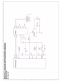
Components include one Atmel ATmega32L, one MAX232, five 1µF
ceramic capacitors required for MAX232 operation10, and various
header pins for outside connections to pins on the ATmega32. Serial
communication is achieved via the T1OUT (transmit) and R1IN
(receive) pins of the MAX23210, connected to pins 3 and 2 of a DB-9
connector, respectively. Pin 5 of the connector is wired to ground. See
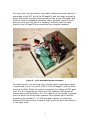
figure 4 for the full schematic.
Figure 4 – Sensor Computer Schematic
An interface had to be created for the sensor computer to facilitate
sensor selection, chip reset, and data transfer. A small square of
prototyping PCB serves as the base for this interface board. For sensor
selection, one terminal of a single-pole single-throw switch connects to
pin 4 of port A (PA4) on the ATmega32, and the other terminal to
5Vdc. When the switch is open (0Vdc at PA4), the ATmega32 goes into
water-quality measurement mode. When the switch is closed (5Vdc at
PA4), lake bottom depth measurement mode is selected. A 10kΩ pulldown resistor is also connected between PA4 and ground, to assure
0Vdc at the pin when the switch is in the open state.
7
For chip reset, one terminal of a normally-closed momentary switch is
connected to the VCC pin of the ATmega32, and the other terminal to
5Vdc. The switch normally allows power to flow to the ATmega32 and
MAX232 chips for standard operation. When pressed, power to both
devices is cut until the switch is released, at which time any data
stored in the ATmega32 are erased and the program reloaded.
Figure 5 – Fully Assembled Sensor Computer
For data transfer, one terminal of a normally-open momentary switch
is connected to pin 2 of port D (PD2) on the ATmega32, and the other
terminal to 5Vdc. When the switch is pressed, the voltage of PD2 goes
from 0 to 5V, triggering an interrupt in the software that dumps all
stored data to the serial port. A 0.1µF capacitor is connected in parallel
with the switch to prevent any bounces from registering as multiple
presses in the software11. A 10kΩ pull-down resistor is connected
between PD2 and ground, to assure 0Vdc at the pin when the switch is
in the open state.
8
The final interface connection is a simple wire from pin 5 of port A
(PA5) on the ATmega32 to pin 2 of port D (PD2) on the navigation
computer. When the boat reaches a waypoint, software in the
navigation computer sets its PD2 to 5V which is registered at PA5 of
the ATmega32, triggering the software to take a reading. A 10kΩ pulldown resistor is connected between PA5 and ground, to assure 0Vdc at
the wire when not at a waypoint.
Between 5V and ground, an LED is wired in series with a 100Ω resistor
to serve as a power indicator light. The LM7805 voltage regulator
mentioned earlier is also contained on this board, as well as an input
for 12V from the boat battery and a 12V output to power the Matrix.
A 5” x 5.5” piece of tinted lexan with strategically drilled holes serves
as a panel for the reset button, data dump button, sensor select
switch, and DB-9 connector. The main board, interface board, and
lexan piece are all mounted on standoffs of varying heights, which are
screwed onto a small piece of plywood. The result is an organized and
compact user interface (figure 5).
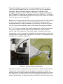
Figure 6 – Sensor Mount Configurations
Two strips of velcro, adhered to the inside of the boat hull just inside
of the front access hatch, secure the sensor computer in place. A
similar system is used to secure the Matrix transceiver just aft of that.
The Matrix’ sonar transducer is screw-mounted to the transom at the
aft end of the boat. An aluminum plate is bolted to the fore deck, and
9
a carabiner is threaded through a hole drilled in the end of it. The
Sonde is then secured in place by clipping it to the carabiner via a
screw eye on the Sonde collar (figure 6).
Software: The ATmega32 can be programmed using assembly or C
languages9. For this project, C was used exclusively. The full code can
be found in the appendix, and specific line numbers will be used in this
section for reference to it. Upon power-up, the software in the
ATmega32 enters an initialization process (1-35). All program
variables are defined, including characters, arrays, floating point
numbers, and counters. In any C code written for a PC, getchar and
putchar routines retrieve characters from the keyboard and send
characters to the screen respectively. In an embedded system such as
this one that has no keyboard or monitor, the getchar and putchar
routines use the serial port to retrieve and send characters. At this
point in the software, these routines are redefined to check for even
parity with every character transmitted or received in even parity
mode, as communication with the Sonde requires this (38-82). Next
comes the data transfer interrupt code, which will be discussed later.
Various ports and timers are then initialized, and the ATmega32’s
USART (serial port) and interrupts are enabled (138-238).
The program then checks PINA.4 of the ATmega32 to see whether 5V
is present. This pin is connected to the sensor select switch on the
interface panel. If the pin is at 5V, the program enters Matrix (lake
bottom depth) mode (247). Otherwise, Sonde (water quality) mode is
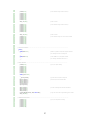
selected (473). See Initialization Program Flowchart in the appendix
for a visual representation of initialization program flow.
If Matrix mode is selected, the program initializes the ATmega32 to
4800 baud, 8 data bits, no parity, & 1 stop bit; required parameters
for communicating with the Matrix (475-477). This is followed by an
indefinite idle period until 5V is seen at PINA.5 (482-489). This pin is
connected to the navigation computer, and a 5V signal indicates that
the boat has reached a waypoint. Once PINA.5 returns to 0V, the
program analyzes each incoming character at the serial port until hex
0x50 (ASCII letter P) is detected (494-497). The only time the Matrix
outputs P is just before a depth reading, which can be viewed in a
terminal window as DPT,X.X, where the X’s are depth digits5. Once P is
detected, the next five characters are temporarily stored (498-502).
The fourth character, which is the first digit of the depth reading, is
reassigned to a slot in an array via a digit counter. The digit counter is
then incremented, and the sixth character, which is the second digit of
the depth reading, is stored in a similar manner. The digit counter is
10
then incremented again (503-506). At this point a variable, cntstop, is
assigned the number in the master counter, and the master counter
incremented (508,509). The ATmega32 has 1000 bytes of storage9,
and each Matrix reading is 2 bytes, so no more than 500 depth
readings may be taken. Using the number assigned to the variable
cntstop from the master counter, a while loop stops depth operations if
500 readings have been taken (510-513). At this point the program
again idles indefinitely until 5V is seen at PINA.5, when the loop
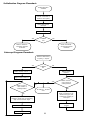
resumes again for another reading. See Matrix Program Flowchart in
the appendix for a visual representation of Matrix program flow. In this
configuration the sensor computer cannot measure lake depths greater
than 9.9 meters. However, this is still greater than the deepest water
level recorded at Lake Merced since at least the mid-1960’s13, so it is
more than adequate.
If Sonde mode is selected, the program initializes the ATmega32 to
9600 baud, 8 data bits, even parity, & two stop bits; required
parameters for communicating with the Sonde (249-251). The Sonde
specification stipulates only one stop bit, but this proved problematic
(see Troubleshooting). The program then waits for the Sonde’s plug-in
string. When the Sonde is plugged into any active serial port, it
automatically sends an initial hexadecimal string of 0x3F3F3F3FFB.
The ATmega32 software gets each of these characters at the serial
port until 0xFB is detected (253-256). After waiting for one second, an
8-byte hex string is sent to the Sonde three times, with a one second
delay between each query, to wake the Sonde from sleep mode
permanently8 (257-288). This is followed by an indefinite idle period
until 5V is seen at PINA.5 (295-302). This pin is connected to the
navigation computer, and a 5V signal indicates that the boat has
reached a waypoint. Once PINA.5 returns to 0V, a round of sensor
readings begins. Each of the five sensors in the Sonde can be triggered
by a specific 8-byte hex string (figure 7)8.
Sensor
Sensor Depth [m]
Temperature [C]
pH [pH Units]
Dissolved Oxygen [mg/L]
Conductivity [mS]
Hex Activation String
01 03 00 30 00 02 C4 04
01 03 00 00 00 02 C4 0B
01 03 00 06 00 02 24 0A
01 03 00 16 00 02 25 CF
01 03 00 0A 00 02 E4 09
Figure 7 – Hex Activation String for Each Sonde Sensor8
Each byte of a given activation string is critical to commanding the
specified reading from the Sonde (figure 8). If any byte is incorrect,
the sensor will not function. The ATmega32 queries the Sonde for a
11
sensor depth reading by sending the string 0x010300300002C404
(307-314). The Sonde responds immediately with a result in the form
of a 9-byte hex string (figure 9)8.
Byte
1
2
3
4
5
6
7
8
Hex Number
01
03
Varies
Varies
Varies
Varies
Varies
Varies
Assignment
Slave Address
Modbus Command 3 – Read Holding Registers
Address of First Register – High Byte
Address of First Register – Low Byte
Number of Registers to Read – High Byte
Number of Registers to Read – Low Byte
Cyclic Redundancy Check – High Byte
Cyclic Redundancy Check – Low Byte
Figure 8 – Byte Designations of a Sonde Activation String8
The first two bytes of the response string are ignored. The ATmega32
proceeds to take in the result once the third byte, 0x04, is detected.
The four bytes of data following contain the sensor result, and are
stored in a dummy array. The final two cyclic redundancy check bytes
are ignored (316-325).
Byte
1
2
3
4
5
6
7
8
9
Hex Number
01
03
04
Varies
Varies
Varies
Varies
Varies
Varies
Assignment
Slave address
Modbus Command 3 – Read Holding Registers
Number of Registers Read x 2
Sensor Reading – Low Word, High Byte
Sensor Reading – Low Word, Low Byte
Sensor Reading - High Word, High Byte
Sensor Reading - high Word, Low Byte
Cyclic Redundancy Check – High Byte
Cyclic Redundancy Check – Low Byte
Figure 9 – Byte Designations of a Sonde Response String8
For correct display later, the sensor result must be converted to a
floating point number. The 4-byte IEEE floating point number format12,
readable by C, stipulates a byte order of high word/high byte, high
word/low byte, low word/high byte, low word/low byte. The four
stored bytes containing the sensor reading, as received from the
Sonde, are not in this order. The issue is resolved by taking the four
bytes from the dummy array and rearranging them into a second array
in the correct order. At this point they are copied sequentially into the
memory location of a float variable and are ready for later output in
the correct format (327-332).
The program waits one second before proceeding to repeat the same
query, response, and rearrangement process for temperature, pH,
12
dissolved oxygen, and conductivity (338-456). Then a variable,
cntstop, is assigned the number in the master counter, and the master
counter incremented (461,462). The ATmega32 has 1000 bytes of
storage, and each Sonde reading is 4 bytes x 5 sensors, so no more
than 50 readings may be taken. Using the number assigned to the
cntstop variable from the master counter, a while loop stops depth
operations if 50 readings have been taken (463-466). At this point the
program again idles indefinitely until 5V is seen at PINA.5, when the
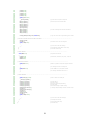
loop resumes again for another reading. See Sonde Program Flowchart
in the appendix for a visual representation of Sonde program flow.
Once all the required Matrix or Sonde readings are recorded, the user
must be able to access the data. This is done by pressing the DATA
button on the interface panel, which briefly sends 5V to pin 2 of port D
(PD2) on the ATmega32, which is also the chip’s external interrupt
pin9. Once an external interrupt is detected, the software breaks from
whatever it is doing and executes the interrupt code. If the button is
pressed and the cntstop variable is 0 (no readings taken), “No sensor
readings taken!” is printed to the serial port (93-96). Otherwise the
program looks to see which sensor is currently selected by detecting
the voltage at PINA.4 of the ATmega32 (99).
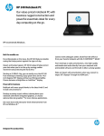
If the Sonde is selected (PINA.4 is 0V), one waypoint number and its
associated sensor depth, temperature, pH, dissolved oxygen, and
conductivity readings are all printed to the serial port (figure 10). The
master counter, set to zero at the start of the interrupt code,
increments and prints the next reading in the same fashion (104-111).
The process ends when the number in the master counter is greater
than the number of total readings saved in the cntstop variable (102).
Figure 10 – Data Transfer Screenshots from Both Sensors
If the Matrix is selected (PINA.4 is 5V), one waypoint number and its
associated lake bottom depth reading are printed to the serial port
(figure 10). The master and digit counters, set to zero at the start of
13
the interrupt code, increment once and twice respectively in the course
of printing one reading (120-129). The process ends when the number
in the master counter is greater than the number of total readings
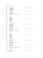
saved in the cntstop variable (118). See Interrupt Program Flowchart
in the appendix for a visual representation of interrupt program flow.
5. Troubleshooting
A number of problems were encountered during the course of this
project. The Sonde communicates at 9600 baud, so the ATmega32 had
to be set to this baud rate as well. ATmega32s come with their system
clock set to a default frequency of 1 MHz. At this clock rate, at 9600
baud, an error was introduced which made communication impossible.
Transmissions from the Sonde were seemingly random strings of
strange characters, a far cry from the specific 9-byte string expected.
The baud rate of an ATmega32 is set via its USART Baud Rate Register
(UBBR) which can only contain integers9. Communication at 9600 baud
using a 1MHz system clock requires that UBBR be set to 5.51, which is
not possible. The closest settings of 5 or 6 allow for baud rates of
10417 or 8929, errors of 8.5 and 6.9% respectively. These errors are
too large for effective communication. The solution was to set the
system clock to 4MHz. At this frequency UBBR can be set to 25, which
allows for a baud rate of 9615. The resulting error was only 0.15% off
of the desired baud rate of 9600, well within reasonable limits. This
also required modifying all baud rate initializations in the code to
comply with the new system clock frequency.
By far the most perplexing problem encountered was an anomaly
where the Sonde would readily respond to an 8-byte hex string sent
from a terminal program on a PC, but would ignore the exact same
string sent from the ATmega32. Cables and adaptors that allowed for
viewing of transmissions between the Sonde and ATmega32 were
purchased and soldered together, verifying that the hex strings sent
from the terminal window and the ATmega32 were seemingly
identical. Finally, an oscilloscope was used to analyze the outputs of
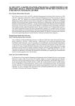
both devices, and the results were telling. At 9600 baud, one bit
should be 104 µS long. Since one frame from each device contained
one start bit, 8 data bits, one parity bit, and one stop bit for a total of
11 bits of data, the total frame length should have been 1144 µS.
However, in this case the stop bit had to be discounted; it could not be
seen since it was a 0V bit that blended seamlessly into the 0V idle
signal that followed it. So the lengths of the frames were considered
using only the visible bits, which now should have been 1040 µS long.
14
The oscilloscope showed that the frame length of the terminal was
longer than 1040 µS, approximately 1175 µS, and that the frame
length of the ATmega32 was shorter, approximately 1000 µS (figure
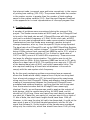
11). It was immediately evident from this that the Sonde prefers a
too-long frame to a too-short one. The most probable explanation is
that while the frame from the terminal was too long, the excess length
of the stop bit easily allowed the Sonde to see the end of the string
and ready itself for the next one. Conversely, the Sonde did not
register the shortened stop bit of the ATmega32 as a full stop bit, so
was never able to recognize the end of the string. The problem was
entirely resolved by modifying the ATmega32 code to send two stop
bits with every frame, which the Sonde could easily recognize as the
end of the string.
Figure 11 – Terminal Frame Length (Top) & ATmega32 Frame Length
(Bottom) @ 250µS/Div
The final problem encountered involved the ATmega32’s inability to
recognize the first incoming byte of a response just after sending out a
string to the Sonde. Each Sonde reading was triggered by an 8-byte
hex string sent by the ATmega32, and the Sonde immediately
responded at a rate seemingly too quick for the ATmega32. Many
different code tricks were tried, without success, to obtain the first
byte of the response string. The string could not be delayed because
the Sonde itself could not be reprogrammed. The first three bytes of
any Sonde response do not vary, so the problem was resolved by
looking for the third byte (0x04) of the response string instead of the
first one.
6. Operation
Lake Bottom Depth: To prepare for a lake bottom contour course,
15
open the fore deck hatch on the boat. Be sure that power is not
connected to the sensor computer. Check to see that the sonar
transducer, serial and power cables are all plugged into their
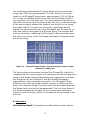
respective sockets on the Matrix. Each socket is specific to its plug, so
there should be no confusion (figure 12).
Figure 12 – Matrix Sensor Connections: (Right to Left) Power, Serial Cable &
Sonar Transducer
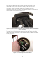
Connect the red & black power connector from the Matrix into either
red & black power connector on the interface board, it does not matter
which (figure 13).
Figure 13 – Connecting Power to the Matrix
16
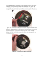
Connect power from the battery to the interface board on the sensor
computer via the remaining red & black connector; the power LED
should light up. Connect the red waypoint indicator cable from the
navigation computer to the same on the sensor computer (figure 14).
Figure 14 – Connecting the Navigation Computer Waypoint Indicator Cable
Press the POWER button on the Matrix 55. The device will turn on and
eventually stop at a government warning screen. Press the EXIT
button one time to exit this screen; the Matrix will automatically go
into depth mode.
Figure 15 – Connecting The Matrix Serial Cable
17
Connect the serial cable from the Matrix to the DB-9 connector on the
sensor computer (figure 15), and close the fore deck hatch.
The boat is now ready for a lake bottom depth course, and the sensor
computer will proceed to take a reading when alerted by the
navigation computer that the boat has reached a waypoint.
Water Quality: With the boat on land, clip the Sonde into the
carabiner at the front of the boat via either screw eye on the Sonde
collar. Be sure that the cable is plugged into the Sonde, and the cable
collar tightly screwed down to prevent water from entering. Check that
the other end of the cable runs through the cable-stays on the deck
and into the entry notch on the aft deck hatch, with no slack cable on
the deck. Thread the Sonde cable through the hull until it is reachable
at the fore deck hatch. Flip the sensor select switch on the sensor
computer to WATER. Connect power from the battery to the interface
board on the sensor computer via either red & black connector; It does
not matter which (figure 16). The power LED should light up.
Figure 16 – Connecting Power to the Sensor Computer
If the sensor computer is already connected to power from a previous
depth reading, press the RESET button before proceeding. Otherwise,
connect the red waypoint indicator cable from the navigation computer
to the same on the sensor computer. Plug the Sonde cable into the
DB-9 connector on the sensor computer. The Sonde should emit an
audible beep. Wait three seconds for the Sonde to wake up. The boat
is now ready for a water quality course, and the sensor computer will
proceed to take a reading when alerted by the navigation computer
that the boat has reached a waypoint.
18
Data Transfer: Once a sensor course is complete and the boat has
returned to shore, open the fore deck hatch and unplug the sensor’s
serial cable from the sensor computer. Take care not to bump the
RESET button as this will erase any stored readings. Connect a null
modem serial cable to the DB-9 connector on the sensor computer. If
a null modem cable is not used, the transfer will not work! Connect the
other end of the null modem cable to the serial port of any laptop
running a terminal program, such as Hyperterminal. The terminal
connection should have the following properties: 4800 baud, no parity,
1 stop bit, no flow control. Once connected to an active terminal
window, press the DATA button on the sensor computer one time
(figure 17).
Figure 17 – Sensor Computer Data Transfer Configuration
Assuming the boat passed through at least one waypoint, data should
appear in the terminal window. If no waypoints were reached, “No
sensor readings taken!” will appear.
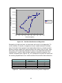
7. Results
Test runs were carried out on South Lake, the largest body of water in
the Lake Merced complex, and meaningful data was successfully
gathered. The course consisted of four waypoints in a roughly
rectangular shape (figure 18).
19
4175500
4175490
North (m, utm grid 10)
4175480
4175470
Boat Route
4175460
Waypoints
4175450
4175440
4175430
4175420
54396 54397 54398 54399 54400 54401 54402 54403 54404 54405
0
0
0
0
0
0
0
0
0
0
East (m, utm grid 10)
Figure 18 – Test Run Boat Route and Waypoints
Examples of captured test run data can be found in the appendix. To
verify validity of results, comparisons were made between the data
from the boat’s first waypoint and past data taken by outside parties.
Where possible, data from approximately the same time of year (late
May) was used. Although deviations were to be expected because of
temperature, rainfall, and pollution variation between samples, the
results compared well (figure 19). All indications are that the boat and
its sensing capabilities are a viable method of scientific data collection.
Measurement
Depth [ft]
Temperature [degrees C]
pH [pH units]
Dissolved Oxygen [mg/L]
Conductivity [mS]
Autonomous Boat
(Waypoint 1)
13.4
19.6
9.3
11.9
0.51
Outside Party Results
13.014
19.115
8.615
10.016
0.6516
Figure 19 – Autonomous Boat & Outside Party Data Comparison
20
8. Conclusion
This project was a success. The sensor computer, on cue from the
navigation computer, was able to activate the sensors and record their
returning data. Once sensing was finished, the sensor computer
successfully transmitted the data to a terminal program on a PC.
Without question it is ready for future use by students looking to
investigate lake bottom depth and water quality, as well as scientists
looking to gather large amounts of data with few logistics.
This project was subjected to just about every asynchronous serial
communications setback possible. Many lessons were learned. Some of
the more significant examples include:
•
•
•
•
•
How to deal with multiple devices communicating at different baud
rates and parities within a single program.
How to compensate for devices that are not communicating at
exactly their specified baud rates.
How to construct a single floating point number from four 8-bit
hex characters in C.
Baud rate errors can be corrected by adjusting system clock
frequency.
Occasionally a device may not be able to react quickly enough to
another device to carry out a given command.
Future Work: There is room for much future work on this platform,
including but not limited to the following:
•
•
•
Currently the data obtained from the sensor computer must be
cross-referenced to a separate list of waypoints reached by the
boat during its water course, to determine which waypoint the
data came from. One possible solution would be to implement
serial communication from the navigation computer to the sensor
computer via their respective SPI ports, allowing latitude &
longitude to be appended to associated sensor data.
The Matrix also outputs water temperature. This could be used to
cross-check temperature readings taken by the Sonde.
Code to calculate a checksum or cyclic redundancy check could be
implemented to reduce errors.
21
9. References
1 – Holden, M. “Autonomous Water Quality Measurements”
2 – Holden, M. “Low-Cost Autonomous Vehicles Using Just GPS”, American Society
of Engineering Education general conference, Salt Lake City, Utah, June 2004
3 - Image taken from www.humminbird.com
4 – Humminbird, “Matrix 55 & 65 Operations Manual”
5 – Humminbird, "Outputting Digital Depth from a Matrix Product to a PC"
6 – Hach Environmental, "DataSonde 4 and MiniSonde Water Quality Multiprobes
User's Manual"
7 - Image taken from www.hachenvironmental.com
8 – Hach Environmental, "Modbus - Function 3 - READ Holding Register"
9 – Atmel Corp, "8-bit AVR Microcontroller with 32K Bytes In-System Programmable
Flash - ATmega32/ATmega32L"
10 – Maxim Integrated Products, "+5V-Powered, Multichannel RS-232
Drivers/Receivers"
11 - "http://www.ece.utep.edu/courses/web3376/concepts/debounce.html"
12 – “http://en.wikipedia.org/wiki/IEEE_floating-point_standard”
13 - “http://www.lakemerced.org/Data/data.html#water”
14 – “http://sfwater.org/Files/Statistics/LakeLevelManagementPlanReport_Dec.pdf”
15 – “http://sfwater.org/Files/Statistics/LLMPApp%20Bpart_2.pdf”
16 - “http://bss.sfsu.edu/holzman/lakemerced/water.htm”
22
10. Appendix
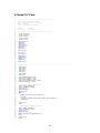
Test Run Examples:
Waypoint 1
-----------------------------Lakebottom Depth = 4.1 meters
Waypoint 1
-----------------------------Sensor Depth = 2.18455 meters
Temperature = 19.55774 degrees C
pH = 9.31965 pH units
Dissolved Oxygen = 11.89111 mg/l
Conductivity = 0.51776 mS
Waypoint 2
-----------------------------Lakebottom Depth = 4.1 meters
Waypoint 2
-----------------------------Sensor Depth = 2.09320 meters
Temperature = 19.49988 degrees C
pH = 9.32011 pH units
Dissolved Oxygen = 11.89142 mg/l
Conductivity = 0.51667 mS
Waypoint 3
-----------------------------Lakebottom Depth = 4.1 meters
Waypoint 4
-----------------------------Lakebottom Depth = 4.2 meters
Waypoint 3
-----------------------------Sensor Depth = 2.13870 meters
Temperature = 19.46908 degrees C
pH = 9.32028 pH units
Dissolved Oxygen = 12.02866 mg/l
Conductivity = 0.51805 mS
\\\\\\\\\\\\\\\\\\\\\\\\\\\\\\\\
Waypoint 1
-----------------------------Lakebottom Depth = 4.2 meters
Waypoint 4
-----------------------------Sensor Depth = 2.07160 meters
Temperature = 19.53631 degrees C
pH = 9.32753 pH units
Dissolved Oxygen = 12.03609 mg/l
Conductivity = 0.51494 mS
Waypoint 2
-----------------------------Lakebottom Depth = 4.2 meters
Waypoint 3
-----------------------------Lakebottom Depth = 4.2 meters
\\\\\\\\\\\\\\\\\\\\\\\\\\\\\\\\
Waypoint 4
-----------------------------Lakebottom Depth = 4.3 meters
Waypoint 1
-----------------------------Sensor Depth = 2.24751 meters
Temperature = 20.01107 degrees C
pH = 8.89823 pH units
Dissolved Oxygen = 10.61682 mg/l
Conductivity = 0.53149 mS
Waypoint 2
-----------------------------Sensor Depth = 2.15318 meters
Temperature = 20.18652 degrees C
pH = 8.94813 pH units
Dissolved Oxygen = 10.66874 mg/l
Conductivity = 0.53187 mS
Waypoint 3
-----------------------------Sensor Depth = 2.14175 meters
Temperature = 20.15548 degrees C
pH = 8.97146 pH units
Dissolved Oxygen = 10.70356 mg/l
Conductivity = 0.53068 mS
Waypoint 4
-----------------------------Sensor Depth = 2.16265 meters
Temperature = 20.07570 degrees C
pH = 8.96583 pH units
Dissolved Oxygen = 10.76794 mg/l
Conductivity = 0.53322 mS
23
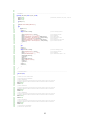
ATmega32 C Code:
1
2
3
4
5
6
7
8
9
10
11
12
13
14
15
16
17
18
19
20
21
22
23
24
25
26
27
28
29
30
31
32
33
34
35
36
37
38
39
40
41
42
43
44
45
46
47
48
49
50
51
52
53
54
55
56
57
58
59
60
61
62
63
64
65
66
67
68
69
70
71
72
73
74
75
76
77
78
79
80
81
82
/*****************************************************
Project : Autonomous Boat Sensor Code
Date : Spring 2006 (Finished on 17May2006)
Author : Bruce White
Company : San Francisco State University
Chip type
: ATmega32
Clock frequency
: 4.000000 MHz
*****************************************************/
#include
#include
#include
#include
#include
char
char
char
char
char
char
char
char
<mega32.h>
<mega32.h>
<stdio.h>
<string.h>
<delay.h>
wakeup=0xFF;
plugin;
data[4];
ignore=0xFF;
dummy[6];
fake[4];
dpt[75];
cntstop=0;
int counter=1;
int counter2=1;
float
float
float
float
float
depth[20];
temp[20];
ph[20];
ldo[20];
cond[20];
// PARITY CHECK--------------------------------------------------------------------------------------------------#define
#define
#define
#define
#define
#define
#define
RXB8 1
TXB8 0
UPE 2
OVR 3
FE 4
UDRE 5
RXC 7
#define
#define
#define
#define
#define
FRAMING_ERROR (1<<FE)
PARITY_ERROR (1<<UPE)
DATA_OVERRUN (1<<OVR)
DATA_REGISTER_EMPTY (1<<UDRE)
RX_COMPLETE (1<<RXC)
// Get a character from the USART Receiver
#ifndef _DEBUG_TERMINAL_IO_
#define _ALTERNATE_GETCHAR_
#pragma used+
char getchar(void)
{
char status,data;
while (1)
{
while (((status=UCSRA) & RX_COMPLETE)==0);
data=UDR;
if ((status & (FRAMING_ERROR | PARITY_ERROR | DATA_OVERRUN))==0)
return data;
};
}
#pragma used#endif
// Write a character to the USART Transmitter
#ifndef _DEBUG_TERMINAL_IO_
#define _ALTERNATE_PUTCHAR_
#pragma used+
void putchar(char c)
{
while ((UCSRA & DATA_REGISTER_EMPTY)==0);
UDR=c;
}
#pragma used#endif
24
83
84
85
86
87
88
89
90
91
92
93
94
95
96
97
98
99
100
101
102
103
104
105
106
107
108
109
110
111
112
113
114
115
116
117
118
119
120
121
122
123
124
125
126
127
128
129
130
131
132
133
134
135
136
137
138
139
140
141
142
143
144
145
146
147
148
149
150
151
152
153
154
155
156
157
158
159
160
161
162
163
164
165
166
167
168
169
170
// INTERRUPT----------------------------------------------------------------------------------------------------------interrupt [EXT_INT0] void ext_int0_isr(void)
{
UCSRC=0x86;
UBRRH=0x00;
UBRRL=0x33;
// 4800 baud, 8 data bits, no parity, 1 stop bit
if(cntstop==0)
{
printf("No sensor readings taken!\n\r");
}
else
{
if(PINA.4==0)
{
counter=1;
while(counter<=cntstop)
{
printf("Waypoint %d\n\r", counter);
printf("------------------------------\n\r");
printf("Sensor Depth = %f meters\n\r", depth[counter]);
printf("Temperature = %f degrees C\n\r", temp[counter]);
printf("pH = %f pH units\n\r", ph[counter]);
printf("Dissolved Oxygen = %f mg/l\n\r", ldo[counter]);
printf("Conductivity = %f mS\n\r\n\r\n\r", cond[counter]);
counter++;
}
}
else
{
counter=1;
counter2=1;
while(counter<=cntstop)
{
printf("Waypoint %d\n\r", counter);
printf("------------------------------\n\r");
printf("Lakebottom Depth = ");
putchar(dpt[counter2]);
counter2++;
printf(".");
putchar(dpt[counter2]);
printf(" meters\n\r\n\r\n\r");
counter++;
counter2++;
}
counter=1;
counter2=1;
}
}
// max 50 readings printed
//
//
//
//
//
//
//
print
print
print
print
print
print
print
waypoint number
separator
depth value
temperature value
ph value
dissolved oxygen value
conductivity value
// max 500 readings printed
// print waypoint number
// print separator
// print "Lakebottom Depth = X.X"
}
// INITIALIZATIONS----------------------------------------------------------------------------------------------------void main(void)
{
// Declare your local variables here
// Input/Output Ports initialization
// Port A initialization
// Func7=In Func6=In Func5=In Func4=In Func3=In Func2=In Func1=In Func0=In
// State7=T State6=T State5=T State4=T State3=T State2=T State1=T State0=T
PORTA=0x00;
DDRA=0x00;
// Port B initialization
// Func7=In Func6=In Func5=In Func4=In Func3=In Func2=In Func1=In Func0=In
// State7=T State6=T State5=T State4=T State3=T State2=T State1=T State0=T
PORTB=0x00;
DDRB=0x00;
// Port C initialization
// Func7=In Func6=In Func5=In Func4=In Func3=In Func2=In Func1=In Func0=In
// State7=T State6=T State5=T State4=T State3=T State2=T State1=T State0=T
PORTC=0x00;
DDRC=0x00;
// Port D initialization
// Func7=In Func6=In Func5=In Func4=In Func3=In Func2=In Func1=In Func0=In
// State7=T State6=T State5=T State4=T State3=T State2=T State1=T State0=T
PORTD=0x00;
DDRD=0x00;
// Timer/Counter 0 initialization
// Clock source: System Clock
25
171
172
173
174
175
176
177
178
179
180
181
182
183
184
185
186
187
188
189
190
191
192
193
194
195
196
197
198
199
200
201
202
203
204
205
206
207
208
209
210
211
212
213
214
215
216
217
218
219
220
221
222
223
224
225
226
227
228
229
230
231
232
233
234
235
236
237
238
239
240
241
242
243
244
245
246
247
248
249
250
251
252
253
254
255
256
257
mode
// Clock value: Timer 0 Stopped
// Mode: Normal top=FFh
// OC0 output: Disconnected
TCCR0=0x00;
TCNT0=0x00;
OCR0=0x00;
// Timer/Counter 1 initialization
// Clock source: System Clock
// Clock value: Timer 1 Stopped
// Mode: Normal top=FFFFh
// OC1A output: Discon.
// OC1B output: Discon.
// Noise Canceler: Off
// Input Capture on Falling Edge
// Timer 1 Overflow Interrupt: Off
// Input Capture Interrupt: Off
// Compare A Match Interrupt: Off
// Compare B Match Interrupt: Off
TCCR1A=0x00;
TCCR1B=0x00;
TCNT1H=0x00;
TCNT1L=0x00;
ICR1H=0x00;
ICR1L=0x00;
OCR1AH=0x00;
OCR1AL=0x00;
OCR1BH=0x00;
OCR1BL=0x00;
// Timer/Counter 2 initialization
// Clock source: System Clock
// Clock value: Timer 2 Stopped
// Mode: Normal top=FFh
// OC2 output: Disconnected
ASSR=0x00;
TCCR2=0x00;
TCNT2=0x00;
OCR2=0x00;
// External Interrupt(s) initialization
// INT0: On
// INT0 Mode: Falling Edge
// INT1: Off
// INT2: Off
GICR|=0x40;
MCUCR=0x02;
MCUCSR=0x00;
GIFR=0x40;
// Timer(s)/Counter(s) Interrupt(s) initialization
TIMSK=0x00;
// USART initialization
// USART Receiver: On
// USART Transmitter: On
// USART Mode: Asynchronous
UCSRA=0x00;
UCSRB=0x18;
// Analog Comparator initialization
// Analog Comparator: Off
// Analog Comparator Input Capture by Timer/Counter 1: Off
ACSR=0x80;
SFIOR=0x00;
// Global enable interrupts
#asm("sei")
while(1)
{
// SENSOR SELECTION---------------------------------------------------------------------------------------------------while(PINA.4==0)
{
UCSRC=0xAE;
UBRRH=0x00;
UBRRL=0x19;
// if PINA.6 is low, sonde is selected sensor
// otherwise depth sensor selected
// 9600 baud, 8 data bits, even parity, 2 stop bits
while(plugin!=0xFB)
{
plugin=getchar();
}
delay_ms(1000);
// look for sonde plugin string ending in FB
// wait 1 second for sonde to go into modbus/even parity
26
258
259
260
261
262
263
264
265
266
267
268
269
270
271
272
273
274
275
276
277
278
279
280
281
282
283
284
285
286
287
288
289
290
291
292
293
294
295
296
297
298
299
300
301
302
303
304
305
306
307
308
309
310
311
312
313
314
315
316
317
318
319
320
321
322
323
324
325
326
327
328
329
330
331
332
333
334
335
336
337
338
339
340
341
342
343
344
345
putchar(0x01);
putchar(0x03);
putchar(0x00);
putchar(0x30);
putchar(0x00);
putchar(0x02);
putchar(0xC4);
putchar(0x04);
// send modbus string to wake sonde up
delay_ms(1000);
// wait 1 second
putchar(0x01);
putchar(0x03);
putchar(0x00);
putchar(0x06);
putchar(0x00);
putchar(0x02);
putchar(0x24);
putchar(0x0A);
// send modbus string to wake sonde up
delay_ms(1000);
// wait 1 second
putchar(0x01);
putchar(0x03);
putchar(0x00);
putchar(0x30);
putchar(0x00);
putchar(0x02);
putchar(0xC4);
putchar(0x04);
// send modbus string to be sure sonde is awake
// WAIT FOR WAYPOINT--------------------------------------------------------------------------------------------------while(1)
{
while(PINA.5==0)
{
;
}
while(PINA.5!=0)
{
;
}
// PINA.5 is guidance computer waypoint indicator
// do nothing when not at a waypoint
// when PINA.5 is 5V, waypoint reached
// do nothing until PINA.5 returns to 0
// DEPTH READING------------------------------------------------------------------------------------------------------putchar(0x01);
putchar(0x03);
putchar(0x00);
putchar(0x30);
putchar(0x00);
putchar(0x02);
putchar(0xC4);
putchar(0x04);
// query for depth reading
while(ignore!=0x04)
{
ignore=getchar();
}
fake[0]=getchar();
fake[1]=getchar();
fake[2]=getchar();
fake[3]=getchar();
ignore=getchar();
ignore=getchar();
// ignore first three bytes of response
// last four bytes are relevant data
data[3]=fake[2];
data[2]=fake[3];
data[1]=fake[0];
data[0]=fake[1];
// number rearrangement for float calculation
memcpy(&depth[counter], data, sizeof data);
delay_ms(1000);
// copy four chars into a single floating point number
// TEMPERATURE READING------------------------------------------------------------------------------------------------putchar(0x01);
putchar(0x03);
putchar(0x00);
putchar(0x00);
putchar(0x00);
putchar(0x02);
putchar(0xC4);
putchar(0x0B);
// query for temperature reading
27
346
347
348
349
350
351
352
353
354
355
356
357
358
359
360
361
362
363
364
365
366
367
368
369
370
371
372
373
374
375
376
377
378
379
380
381
382
383
384
385
386
387
388
389
390
391
392
393
394
395
396
397
398
399
400
401
402
403
404
405
406
407
408
409
410
411
412
413
414
415
416
417
418
419
420
421
422
423
424
425
426
427
428
429
430
431
432
433
while(ignore!=0x04)
{
ignore=getchar();
}
fake[0]=getchar();
fake[1]=getchar();
fake[2]=getchar();
fake[3]=getchar();
ignore=getchar();
ignore=getchar();
// ignore first three bytes of response
// last four bytes are relevant data
data[3]=fake[2];
data[2]=fake[3];
data[1]=fake[0];
data[0]=fake[1];
// number rearrangement for float calculation
memcpy(&temp[counter], data, sizeof data);
delay_ms(1000);
// copy four chars into a single floating point number
// PH READING---------------------------------------------------------------------------------------------------------putchar(0x01);
putchar(0x03);
putchar(0x00);
putchar(0x06);
putchar(0x00);
putchar(0x02);
putchar(0x24);
putchar(0x0A);
// query for ph reading
while(ignore!=0x04)
{
ignore=getchar();
}
fake[0]=getchar();
fake[1]=getchar();
fake[2]=getchar();
fake[3]=getchar();
ignore=getchar();
ignore=getchar();
// ignore first three bytes of response
// last four bytes are relevant data
data[3]=fake[2];
data[2]=fake[3];
data[1]=fake[0];
data[0]=fake[1];
// number rearrangement for float calculation
memcpy(&ph[counter], data, sizeof data);
delay_ms(1000);
// copy four chars into a single floating point number
// DO READING--------------------------------------------------------------------------------------------------------putchar(0x01);
putchar(0x03);
putchar(0x00);
putchar(0x16);
putchar(0x00);
putchar(0x02);
putchar(0x25);
putchar(0xCF);
// query for dissolved oxygen reading
while(ignore!=0x04)
{
ignore=getchar();
}
fake[0]=getchar();
fake[1]=getchar();
fake[2]=getchar();
fake[3]=getchar();
ignore=getchar();
ignore=getchar();
// ignore first three bytes of response
// last four bytes are relevant data
data[3]=fake[2];
data[2]=fake[3];
data[1]=fake[0];
data[0]=fake[1];
// number rearrangement for float calculation
memcpy(&ldo[counter], data, sizeof data);
delay_ms(1000);
// copy four chars into a single floating point number
// CONDUCTIVITY READING-----------------------------------------------------------------------------------------------putchar(0x01);
putchar(0x03);
putchar(0x00);
// query for conductivity reading
28
434
435
436
437
438
439
440
441
442
443
444
445
446
447
448
449
450
451
452
453
454
455
456
457
458
459
460
461
462
463
464
465
466
467
468
469
470
471
472
473
474
475
476
477
478
479
480
481
482
483
484
485
486
487
488
489
490
491
492
493
494
495
496
497
498
499
500
501
502
503
504
505
506
507
508
509
510
511
512
513
514
515
516
517
518
putchar(0x0A);
putchar(0x00);
putchar(0x02);
putchar(0xE4);
putchar(0x09);
while(ignore!=0x04)
{
ignore=getchar();
}
fake[0]=getchar();
fake[1]=getchar();
fake[2]=getchar();
fake[3]=getchar();
ignore=getchar();
ignore=getchar();
// ignore first three bytes of response
// last four bytes are relevant data
data[3]=fake[2];
data[2]=fake[3];
data[1]=fake[0];
data[0]=fake[1];
// number rearrangement for float calculation
memcpy(&cond[counter], data, sizeof data);
// copy four chars into a single floating point number
// ADVANCE COUNTER & RESET FOR NEXT WAYPOINT--------------------------------------------------------------------------cntstop=counter;
counter++;
while(cntstop>=50)
{
;
}
// advance counter for next waypoint
// prevent more than 50 readings
}
}
// end while loop inside water sensor loop
// end water sensor loop
// DEPTH SENSOR-------------------------------------------------------------------------------------------------------while(PINA.4!=0)
{
UCSRC=0x86;
UBRRH=0x00;
UBRRL=0x33;
// depth sensor selected
// 4800 baud, 8 data bits, no parity, 1 stop bit
// WAIT FOR WAYPOINT--------------------------------------------------------------------------------------------------while(PINA.5==0)
{
;
}
while(PINA.5!=0)
{
;
}
// PINA.5 is guidance computer waypoint indicator
// do nothing when not at a waypoint
// when PINA.5 is 5V, waypoint reached
// do nothing until PINA.5 returns to 0
// DEPTH READING------------------------------------------------------------------------------------------------------while(dummy[0]!=0x50)
{
dummy[0]=getchar();
}
dummy[1]=getchar();
dummy[2]=getchar();
dummy[3]=getchar();
dummy[4]=getchar();
dummy[5]=getchar();
dpt[counter2]=dummy[3];
counter2++;
dpt[counter2]=dummy[5];
counter2++;
dummy[0]=0;
cntstop=counter;
counter++;
while(cntstop>=500)
{
;
}
// look for letter P at serial port
//
//
//
//
//
//
ignore letter T
ignore comma
store first digit of depth reading
ignore period
store second digit of depth reading
rearrange depth reading numbers for later output
// prevent more than 500 readings
}
// end depth sensor loop
}
// end program while loop
// end main loop
}
29
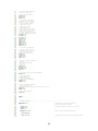
Initialization Program Flowchart:
Define libraries &
variables
Redefine getchar and
putchar commands to
check for even parity
Define data transfer
interrupt
Initialize registers
Yes
Is PINA.4
5V?
No
Matrix is selected –
see Matrix program
flowchart
Sonde is selected –
see Sonde program
flowchart
Interrupt Program Flowchart:
Switch to 4800 baud,
no parity, 1 stop bit
Yes
Is PINA.4
5V?
No
Master counter
reset to 1
Master counter reset to 1
Digit counter reset to 1
Yes
Master counter >
max number of
readings taken?
Yes
Do nothing – all data
sent
Master counter >
max number of
readings taken?
No
Print waypoint number,
depth, temperature, pH,
dissolved oxygen, and
conductivity reading to
serial port
No
Print waypoint number & depth
reading to serial port, incrementing
digit counter between digits
Increment master
counter
Increment master counter
Increment digit counter
30
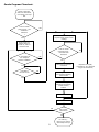
Sonde Program Flowchart:
Sonde is selected Switch to 9600 baud,
even parity, two stop
bits
Look for Sonde
plugin string – has
0xFB been
detected?
No
Send 8-byte hex string to
request Sonde single-sensor
reading
Yes
Send 8-byte hex
wakeup string to
Sonde 3x, wait 1s
between each
Look for Sonde
response string –
has 0x04 been
detected?
Is 5V signal from
nav computer
present at PINA.5?
No
Yes
Store next 4 returned
characters
Yes
Has PINA.5
returned to 0V?
No
No
Rearrange characters
for storage as floating
point number
Yes
Store rearranged
characters sequentially
in float memory
location
Wait 1 second
Increment counter
No
Has counter
reached 50?
Yes
Do nothing –
memory full, wait for
data dump interrupt
31
Repeat 5x for depth,
temperature, pH, dissolved
oxygen & conductivity
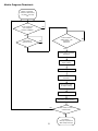
Matrix Program Flowchart:
Matrix is selected Switch to 4800 baud,
no parity, one stop
bit
Is 5V signal from
nav computer
present at PINA.5?
No
Yes
Has PINA.5
returned to 0V?
Look for Matrix
depth string – has
0x50 been
detected?
No
Yes
Yes
Ignore next 2 returned
characters
Store first digit of
depth reading
Increment digit counter
Ignore next returned
character
Store second digit
of depth reading
Increment digit counter
Increment master counter
No
Has master counter
reached 500?
Yes
32
Do nothing –
memory full, wait for
data dump interrupt
No
33