1
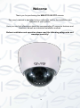
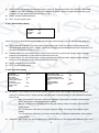
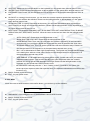
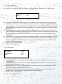
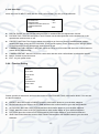
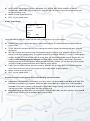
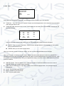
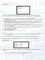
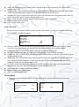
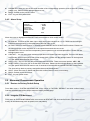
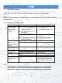
MINI-PTZ-23X 23X ZOOM ANALOGUE PTZ CAMERA User’s Manual V1.0 10 / 2013 i Table of Contents 1 FEATURES AND FUNCTIONS ................................................................................................ 1 1.1 General Introduction .......................................................................................................................................... 1 1.2 Features .............................................................................................................................................................. 1 1.2.1 On-Screen Menu ............................................................................................................................................. 1 1.2.2 Proportional Pan and Tilt ................................................................................................................................. 1 1.2.3 On-screen Tips ................................................................................................................................................ 1 1.2.4 Preset Setup and Call ...................................................................................................................................... 1 1.2.5 Auto Scan ........................................................................................................................................................ 1 1.2.6 Auto Touring .................................................................................................................................................... 2 1.2.7 Auto Pattern ..................................................................................................................................................... 2 1.2.8 Privacy Masking ............................................................................................................................................... 2 1.2.9 Auto Flip ........................................................................................................................................................... 2 1.2.10 Self-diagnosis .............................................................................................................................................. 2 1.2.11 Day/Night Mode (B/W & Color Mode) ......................................................................................................... 2 1.2.12 Auto Focus .................................................................................................................................................. 2 1.2.13 Backlight Compensation .............................................................................................................................. 2 1.2.14 Pan Tilt and Zoom ....................................................................................................................................... 2 1.2.15 3D Intelligent Location ................................................................................................................................. 3 1.2.16 Idle Status .................................................................................................................................................... 3 1.2.17 Image Stabilizer/Flip .................................................................................................................................... 3 2 MENU ....................................................................................................................................... 4 2.1 Screen Menu Index ............................................................................................................................................ 4 2.2 Self-diagnosis System Information .................................................................................................................. 5 2.3 Main Menu ........................................................................................................................................................... 5 2.4 Menu Operation .................................................................................................................................................. 6 2.4.1 System Information .......................................................................................................................................... 6 2.4.2 Display Setting ................................................................................................................................................. 7 2.4.3 Camera Setting ................................................................................................................................................ 8 2.4.4 Function Setting ............................................................................................................................................. 12 2.4.5 Alarm Setup ................................................................................................................................................... 19 2.5 3 Abnormal Phenomenon Operation ................................................................................................................ 19 2.5.1 Restore to Factory Default Setup .................................................................................................................. 19 2.5.2 Irregular PTZ Movement ................................................................................................................................ 19 CABLE CONNECTION .......................................................................................................... 20 ii 3.1 4 Combination Cable Connection...................................................................................................................... 20 FAQ ........................................................................................................................................ 21 4.1 Daily Maintenance ............................................................................................................................................ 21 4.2 Problems and Solutions .................................................................................................................................. 21 iii Welcome Thank you for purchasing the MINI-PTZ-23X PTZ camera. This user’s manual is designed to be a reference tool for the installation and operation of your system. Here you can find information about the corresponding IP camera’s features and functions, as well as a detailed installation method. Before installation and operation please read the following safeguards and warnings carefully! iv Important Safeguards and Warnings 1.Electrical safety All installation and operation here should conform to your local electrical safety codes. We assume no liability or responsibility for all the fires or electrical shock caused by improper handling or installation. We are not liable for any problems caused by unauthorized modification or attempted repair. 2.Transportation Security No heavy stress, violent vibration or contact with water is allowed during transportation, storage and installation. Please use the original packing material (or the material of the same quality) when you ship it back to the manufacturer. 3.Installation Do not apply power to the product before completing installation. Do not put object(s) on the product. 4.Environment This product should be installed in a cool, dry place away from direct sunlight, inflammable, explosive substances and etc. Please keep it away from environments that contain electromagnetic radiation or objects that produce it. Please keep sound ventilation around the device at all times. Do not allow the water and other liquid to penetrate into the device if casing has been compromised. This series product complies with the IP66 standard specified in the Degrees of Protection Provided by Enclosure. Please make sure the CCD (CMOS) component is away from the radiation of the laser beam device. Otherwise it may result in CCD (CMOS) optical component damage. 5. Daily Maintenance Current series product has no power button. Please unplug all corresponding power cables before your begin installation or daily maintenance work. Please keep the dustproof cap back to protect the CCD or CMOS part if the device does not work for a long time. Do not touch CCD (CMOS) component. You can use the blower to clean the dust on the surface of the device. You can use the dry cloth with some alcohol or mild detergent to clear if necessary. Do not use volatility solvent such as the benzene or thinner, or detergent with strong abradability. It may result in lens damage or it may adversely affect the device performance. v If there is too much dust, please use the water to dilute the mild detergent first and then use it to clean the device. Finally use the dry cloth to clean the device. 6. About Accessories Always use all the accessories recommended by manufacturer. Before installation, please open the package and check that all the components are included in the package. Contact your local retailer ASAP if something is missing in your package. vi 1 Features and Functions 1.1 General Introduction This 4-inch analogue intelligent PTZ dome camera gives you 23X optical zoom to scrutinise far away objects closer. It adopts a new configuration design and is easy to install during project construction. This is a digitally intelligent product that can provide you with vivid video visuals. The design aesthetics also allows it to be incorporated into many modern settings. At the same the shape and materials provides it with the robustness to survive a variety of weather conditions. Internal technology allows for the PTZ rotation speed to be automatically adjusted according to lens zoom speed. It supports various languages, real-time clock function, blind spot recognition and protocol auto recognition. It also gives you a full 360° continuously pan, 92°tilt and 180° auto flip. 1.2 Features This PTZ speed dome has the following features: 1.2.1 On-Screen Menu This series product menu supports multiple languages. It is easy for you to view dome information and configure dome, camera parameters. 1.2.2 Proportional Pan and Tilt This function keeps the image from moving too fast when there is a large amount of zoom. The PTZ camera continually decreases or increases pan and tilt speeds in proportion to depth of zoom. When zooms speed increases, the camera moving speed becomes slow. When zooms speed decreases, the camera moving speed becomes fast. 1.2.3 On-screen Tips Here you can view: Dome title and system version (Software and hardware) Dome system temperature. (Optional. You can disable this function) Dome pan/tilt coordinates, preset ID. 1.2.4 Preset Setup and Call Preset function is to save the address information (such as PTZ pan/tilt, focus and etc) to the memory so that you can quickly adjust the dome and PTZ to the correct position. 1.2.5 Auto Scan Camera scans back and forth regularly along the horizontal field. Here you need to set left and right limit and scan speed. You can set 5 scanning paths. 1 1.2.6 Auto Touring Add addresses into a routine in a desired order and then set time and stop duration for each address. The dome will begin an auto touring between these addresses. Each touring path can contain max 32 presets. 1.2.7 Auto Pattern Memorises dome operations such as pan, tilt, and zoom to repeat. You can call it to repeat the previous operation. 1.2.8 Privacy Masking Privacy masking is a user-defined, four-sided area that cannot be viewed by you. The masking area will move with pan and tilt functions and automatically adjust in size as the lens zooms. 1.2.9 Auto Flip As long as you continue to hold the keyboard joystick in the down position, the dome rotates 180 degrees and repositions itself for uninterrupted viewing of any subjects that passes directly beneath the dome. 1.2.10 Self-diagnosis There is a self-diagnosis procedure when camera boots up. Tilt and vertical engine check Camera diagnostics 1.2.11 Day/Night Mode (B/W & Color Mode) Auto/manual switches in low illumination. Auto: camera will automatically adjust CCD light level. Manual: use menu or function keys to select auto/manual/schedule settings. This function needs the speed dome driver (camera) supported. 1.2.12 Auto Focus Supports auto focus function. 1.2.13 Backlight Compensation Balance the brightest and darkest sections of a scene to produce a more vivid picture. 1.2.14 Pan Tilt and Zoom Supports zoom in and zoom out during tilt and pan movement. In this period focus and iris are both in auto mode to get vivid image. 2 1.2.15 3D Intelligent Location It supports the 3D intelligent positioning function, where the camera can auto track to the specified zone. 1.2.16 Idle Status When there is no available order, you can use menu to set dome idle status after specified duration. 1.2.17 Image Stabilizer/Flip You can enable image stabiliser function and flip in the menu. When there is vibration, this I.S. function can guarantee video stability, and when it flips, you can view the video more clearly. 3 2 Menu 2.1 Screen Menu Index Note: ERR means current setup is invalid; you need to restores speed dome factory default setup. Slight difference may be found due to different series. SYSTEM SETTING SYSTEM INFORMATION ADDR INFORMATION SET NORTH LANGUAGE FACTORY DEFAULT RESTART BACK EXIT DISPLAY SETTING PRESET AZIMUTH DISP POSITION ZOOM DISP INSIDE TEMP TITILE DISPLAY BACK EXIT CAMERA SETTING FUNCTION SETTING WB SETTING EXPOSURE SETTING DAY/NIGHT SETTING FOCUS SETUP ZOOM SPEED APERTURE APERTURE CNT LEVEL NEXT PAGE BACK EXIT ALARM SETTING PRESET AUTO PAN AUTO SCAN TOUR PATTERN IDLE MOTION NEXT PAGE BACK EXIT EXIT ALARM NO ACTION PARAMETER CONTACT RELAY OUT RESET DELAY SAVE BACK EXIT The above diagram illustrates the overall structure of the speed dome setup menu. 4 Note: ERR means current setup is invalid. Please make sure all the cable connections are correct. 2.2 Self-diagnosis System Information ADDR BAUD RATE PARITY SOFTWARE BACK :001-H :9600 :NONE :V1.03.0.RHAJDV EXIT After installation, please connect speed dome to power. The system goes on a self-diagnosis routine, and then it pops up the above interface to show the system information. If there is anything wrong during the self-diagnosis, system pops up error code. The above interface disappears after speed dome received the first command (or the display time lasts for 4minutes.) ADDR: Here you can view dome address information. For example, 001-H, 1 is the address number, -H is hard address mode. –S is software address mode. Baud rate: Dome communication baud rate. Parity: Communication parity bit format. Software: Dome PTZ software version. When you are using the control keyboard or the matrix host to control the device, please make sure the control parameter of the keyboard or the matrix host is the same with the speed dome OSD (including address, baud rate, parity). Please make sure the cable connection is OK. 2.3 Main Menu You can open the PTZ camera menu via control keyboard, matrix, or speed dome control terminal. SYSTEM SETTING DISPLAY SETTING CAMERA SETTING FUNCTION SETTING ALARM SETTING EXIT SYSTEM INFORMATION:Dome self-diagnosis information, address information, system time setup, set north direction, language, factory default setup, reboot and so on. DISPLAY INFORMATION: Display dome preset title, azimuth display, time, direction, dome internal temperature information. CAMERA PARAMETERS:Display dome white balance setup, camera function setup, day/night setup, shutter setup and etc. 5 FUNCTION SETTING: Set preset, pan, scan, auto cruise, pattern, idle function, time task and privacy mask function. ALARM SETTING:Set dome alarm number, action, contact, replay out, reset time, etc. EXIT: Log out of the system menu. 2.4 Menu Operation In the PTZ camera main menu, you can use the left/right button on the keyboard or in the camera’s terminal menu to configure the system menu. Before setup, please move the cursor to the current item you want to configure. In main menu, please click confirm button to go to the sub menu or use left/right key to configure setup. Use up/down button to select back option and then click confirm button to go back to the previous menu. Use up/down button to select exit option and then click confirm button to log out system menu. All setups here will not be lost when you encounter a power failure. 2.4.1 System Information SYSTEM INFORMATION ADDR INFORMATION SET NORTH LANGUAGE :ENGLISH FACTORY DEFAULT RESTART BACK EXIT SYSTEM INFORMATION: Move the cursor to SYSTERM INFORMATION and then click the confirm button to go to the third submenu. ADDR INFORMATION: Move the cursor to SITE INFORMATION and then click confirm button to go to the third submenu. SET NORTH: Set the camera’s benchmark direction so that you can know the angle between the benchmark and then current location. Please move the cursor to the option and then click confirm button until you see O.K. option. Now you have set the north direction. LANGUAGE: The dome menu language. There are several languages for you to select. Please use the left/right button on the keyboard or in the speed dome terminal menu to set. FACTORY DEFAULT: Restore dome factory default setup. Please move the cursor to the option and then click confirm button until you see O.K. Now you can see the IP dome begin rebooting to restore factory default setup. RESTART: Reboot the camera. BACK: Go back to the previous menu. EXIT: Log out of the system menu. 6 2.4.1.1 System information ADDR BAUD RATE PARITY SOFTWARE BACK : 001-H :9600 :NONE :V1.03.0.RHAJDV EXIT Move the cursor to SYSTEM INFORMATION and then click the confirm button, you will see the above interface. Here you can view the dome’s basic information. 2.4.1.2 Address Information ADDR TYPE ADDR-HARD ADDR-SOFT BACK :HARD :1 :0 EXIT Move the cursor to SITE INFORMATION and then click confirm button. ADDR TYPE: There are two options: soft and hard. Please use the left/right button on the keyboard or in the speed dome terminal menu to set. Please click the OK button to confirm ADDR-HARD: It is an address you can set in the dial switch. You cannot modify it through the software. ADDR-SOFT: You can set address via software. It is to say, you can use menu to modify dome address. The value ranges from 0 to 255. BACK: Go back to the previous menu. EXIT: Log out system menu. 2.4.2 Display Setting PRESET AZIMUTH DISP POSITION ZOOM DISP INSIDE TEMP TITLE DISP BACK :ON :ON :OFF :OFF :OFF :OFF EXIT Move the cursor to DISPLAY SETUP and then click confirm button, you can go to the third submenu. Please use the left/right button on the keyboard or in the speed dome terminal menu to set. After completing the setup, please click the save button to save current setup. PRESET TITLE: Display dome preset title or not. Please use the left/right button on the keyboard or in the speed dome terminal menu to set. You can go to Function Setup->Preset section to set corresponding preset value and preset title. 7 AZIMUTH DISP: Displays the cameras current coordinates or not. Please use the left/right button on the keyboard or in the speed dome terminal menu to set POSITION: Displays the angle between the benchmark and then current location. Please use the left/right button on the keyboard or in the speed dome terminal menu to set. ZOOM DISP: Display speed dome zoom speed or not. Please use the left/right button on the keyboard or in the speed dome terminal menu to set. INSIDE TEMPERATURE: Display dome internal temperature or not. There are three options: ℃/F/Off. Please use the left/right button on the keyboard or in the speed dome terminal menu to set. TITLE DISPLAY: Here you can set to display speed dome position information and etc. You can use the speed dome control terminal to set the detailed title information. Please use the left/right button to set. BACK: Go back to the previous menu. EXIT: Log out system menu. 2.4.3 Camera Setting Before the operation, please make sure your camera supports the corresponding function. WB SETTING EXPOSURE SETTING DAY/NIGHT SETTING FOCUS SETTING ZOOM SPEED APERTURE APERTURE RESTRAIN NEXT PAGE BACK :8 :9 :10 EXIT Move the cursor to CAMERA SETTING and then click confirm button, you can go to the submenu. WHITE BALANCE SETUP: Move the cursor to current option and then click confirm button, you can go to the third menu. EXPOSURE SETTING: Move the cursor to current option and then click confirm button, you can go to the third menu. DAY/NIGHT: Set day/night mode. Move the cursor to current option and then click confirm button, you can go to the third menu. There are three options: auto/manual/off. Please use the left/right button on the keyboard or in the speed dome terminal menu to set. Please make sure your product supports this function. FOCUS SETTING: This is to set the camera focus mode, focus limit, etc. Please use the left/right button on the keyboard or in the speed dome terminal menu to set. FOCUS LIMIT: This is to set the distance between the camera and the object. It can prevent the focus distance being too small, which may result in an unclear image. At the same time, you can change the distance to change the focus speed. ZOOM SPEED: The bigger the value, the faster the speed. Please use the left/right button on the keyboard or in the speed dome terminal menu to set. APERTURE: This is to adjust the lens to achieve clearer video footage. Please use the left/right button on the keyboard or in the speed dome terminal menu to set. APERTURE RESTRAIN: System can auto reduce the aperture to lower the video noise when it is in a poorly illuminated environment. Please use the left/right button on the keyboard or in the speed dome terminal menu to set. 8 NEXT PAGE: This includes the following options: DIGITAL ZOOM, PICTURE FLIP, FREEZE FUNCTION, CAMERA FACTORY DEFAULT SETUP and CAMERA RESTART. Please use the left/right button on the keyboard or in the speed dome terminal menu to set. BACK: Go back to previous menu. EXIT: Log out system menu. 2.4.3.1 White Balance Setup WB MODE R GAIN B GAIN BACK : AUTO : 82 : 58 EXIT Move the cursor to WHITE BALANCE MODE and then click confirm button, you can then go to the submenu. WHITE BALANCE MODE: Set white balance adjustment mode. There are several modes such as auto, auto trace white balance, indoor, outdoor, and manual. Please use the left/right button on the keyboard or in the speed dome terminal menu to set. R GAIN: Before you set R GAIN option, please note it will not be in auto mode. Please use the left/right button on the keyboard or in the camera’s terminal menu to set. B GAIN: Before you set B GAIN option, please note it will not be in auto mode. Please use the left/right button on the keyboard or in the camera’s terminal menu to set. BACK: Go back to previous menu. EXIT: Log out system menu. 2.4.3.2 Exposure Setting AE MODE GAIN SETTING SHUTTER IRIS SETTING EXPOSURE COMP SLOW AE SLOW SHUTTER NEXT PAGE BACK :AUTO :2 :1/50 :4 :8 :1 :ON AGC GAIN LIMIT SLOW SHUTTER LIMIT NOISE REDUCTION 3D NOISE REDUCTION BLC WDR ENABLE AE RECOVERY BACK :2 :1/25 :3 :1 :OFF :15MIN EXIT EXIT AE MODE: This is where you can set the camera exposure mode. This includes: auto/manual/AV (iris priority)/TV (shutter priority). Please use the left/right button on the keyboard or in the speed dome terminal menu to set. o Auto: This becomes valid after you set the exposure compensation, backlight compensation (BLC), slow shutter, wide dynamic region (WDR). o Manual: This becomes valid after you set the gain setting, shutter, iris setting, wide dynamic region (WDR). o AV: This becomes valid after you set the exposure setting, iris setting, wide dynamic region (WDR). o TV: This becomes valid after you set the shutter setting, exposure compensation, wide dynamic region (WDR). GAIN SETTING: Please use the left/right button on the keyboard or in the speed dome terminal menu to set. 9 SHUTTER: Please use the left/right button on the keyboard or in the speed dome terminal menu to set. IRIS SETTING: Please use the left/right button on the keyboard or in the speed dome terminal menu to set. EXPOSURE COM: Please use the left/right button on the keyboard or in the speed dome terminal menu to set. SLOW AE: In a strongly lit environment, you can lower the camera exposure speed when capturing the image so you can enhance the definition. Please use the left/right button on the keyboard or in the speed dome terminal menu to set. SLOW SHUTTER: In a poorly illuminated environment, you can lower the cameras auto exposure time when capturing an image and enhance the definition. Please use the left/right button on the keyboard or in the speed dome terminal menu to set. NEXT PAGE: This includes: GAIN MAX LIMIT, SLOW SHUTTER LIMIT, NOISE REDUCTION, 3D NOISE REDUCTION, BLC, WDR, BACK, and EXIT. Move the cursor to the item and then click the left/right button to set. o AUTO GAIN LIMIT: Please click the left/right button to set. o SLOW SHUTTER LOW LIMIT: Please click the left/right button to set. o NOISE REDUCTION: There may be noise when the camera is monitoring in low illumination environments. You can use the digital filter to process the noise to guarantee the clear video. o 3D NOISE REDUCTION: This is to set the speed dome 3D noise reduction setup. Please use the left/right button on the keyboard or in the speed dome terminal menu to set. o BLC: It is an abbreviation for Back Light Compensation. The System can compensate the object in the dark light to achieve a clear video. Please use the left/right button on the keyboard or in the speed dome terminal menu to set. o WDR ENBALE: It is an abbreviation for wide dynamic region. Please make sure your camera supports current function. This function can adjust the video brightness when the contrast between the strong light and the dark light is too high. Please use the left/right button on the keyboard or in the speed dome terminal menu to set. o AE RECOVERY: Manually click the “+” and “-“button on the PTZ interface, the system can resume previous exposure value after specified time (The exposure value does not resume if this function is off.). BACK: Go back to previous menu. EXIT: Log out system menu. 2.4.3.3 WDR Move the cursor to WDR and then click confirm button, you can then go to the submenu. WDR MODE BACK :OFF EXIT WDR MODE: Click Left/right button to enable/disable camera WDR function. BACK: Go back to previous menu. EXIT: Log out system menu. 10 2.4.3.4 Day/Night Setting Move the cursor to DAY/NIGHT SETTING and then click confirm button, you can then go to the submenu. DAY/NIGHT THRESHOD BACK : AUTO : 05 EXIT DAY/NIGHT: Please use the left/right button on the keyboard or in the speed dome terminal menu to set. DAY TIME: Current setup becomes valid when day/night mode’s time is set. Move the cursor to the DAY TIME item and then click confirm button to go to setup. Please use the user up/down button to set the value. After completing the setup, please click confirm button to exit and move the cursor to ‘Save’ button to save current setup. NIGHT TIME: Current setup becomes valid when day/night mode’s time is set. Move the cursor to DAY TIME item and then click confirm button to go to setup. Please use the user up/down button to set the value. After completing setup, please click confirm button to exit and move the cursor to save button to save current setup. THRESHOLD: The speed dome can switch the day/night mode when it reached the threshold you set here. SAVE: This button is for DAY TIME and NIGHT TIME setup. After you set the day time (or night time), you need to move the cursor here and then click confirm button to save current time setup. For other setups, you do not need to use this button. BACK: Go back to previous menu. EXIT: Log out system menu. 2.4.3.5 Focus Setup FOCUS MODE FOCUS LIMIT AF SENSITIVITY IR CORRECTION BACK : AUTO :10CM : HGIH : OFF EXIT FOCUS MODE: This is to set the camera focus mode. It includes several modes such as auto, manual, semiautomatic, etc. FOCUS LIMIT: This is to set the camera focus limit. Please use the left/right button on the keyboard or in the speed dome terminal menu to set. FOCUS SENSITIVITY: This is to set the camera focus sensitivity. Please use the left/right button on the keyboard or in the speed dome terminal menu to set. IR LIGHT FOCUS CORRECTION: This is to set the camera IR light focus correction. Please use the left/right button on the keyboard or in the speed dome terminal menu to set. BACK: Go back to previous menu. EXIT: Log out system menu. 11 2.4.3.6 Next Page Move the cursor to NEXT PAGE and then click confirm button, you can go to the submenu. DIGITAL ZOOM : OFF PICTURE FLIP :OFF FREEZE FUNC : OFF CAMERA FACTORY DEFAULT CAMERA RESTART BACK EXIT DIGITAL ZOOM: You can use the left/right button to enable/disable the digital zoom function. PICTURE FLIP: There are two options: on/off. Please use the left/right button on the keyboard or in the speed dome terminal menu to set. FREEZE FUNCTION: This function allows the system to go from one preset to another preset, without showing the video during the PTZ movement. There are two options: on/off. Please use the left/right button on the keyboard or in the speed dome terminal menu to set. CAMERA FACTORY DEFAULT SETTING: Move the cursor to current item and then click confirm button to restore factory default setup. CAMERA RESTART: Move the cursor to current item and then click confirm button to reboot the camera. BACK: Go back to previous menu. EXIT: Log out system menu. 2.4.4 Function Setting PRESET AUTO PAN AUTO SCAN TOUR PATTERN IDLE MOTION NEXT PAGE BACK EXIT Please go back to main menu and move the cursor to FUNCTION SETTING, click confirm button. You can see the above interface. PRESET: Move the cursor to PRESET and then click confirm button to go to the third submenu. AUTO PAN: Move the cursor to AUTO PAN and then click confirm button to go to the third submenu. AUTO SCAN: Move the cursor to SCAN and then click confirm button to go to the third submenu. TOUR: Move the cursor to AUTO TOUR and then click confirm button to go to the third submenu. PATTERN: Move the cursor to PATTERN and then click confirm button to go to the third submenu. IDLE FUNCTION: Move the cursor to IDLE FUNCITON and then click confirm button to go to the third submenu. 12 NEXT PAGE: This includes: PRIVACY MASKING, PTZ SPEED, SET ZERO, POWER UP, MENU PASSWORD, MENU IDEL, PTZ AUTO STOP, and HEATER. Move the cursor to the item and then click the confirm button to set. . BACK: Go back to previous menu. EXIT: Log out system menu. 2.4.4.1 Preset Setup PRESET NO :001 TITLE :PRESET1 SETTING CALL BACK EXIT EXIT Move the cursor to PRESET button and then click confirm button to go to set interface. PRESET NO: Please use left/right key to modify preset number. The different protocols support different preset values. TITLE: Title text is the label used for you to identify the camera. System will automatically name a title for the camera. SETTING: Please input preset number first and then select the monitor zone. Please move the cursor to setting and click the confirm button. The system will pop up a message: PRESET: *** Here *** means preset number. And the SETTING column pops up an OK. Now you successfully added a preset. Please note, you need to enable display preset title function first (Main menu->display setting->preset title). Repeat the above procedures to set more presets. When you want to modify a preset, you can input the preset number you want to modify and then follow the above steps to set the preset. CALL: This is to recall a preset. Move the cursor to ‘PRESET NO’ and then input a corresponding preset value. Then move the cursor to CALL and then click confirm button to go to a preset. BACK: Go back to previous menu. EXIT: Log out system menu. For PELCO protocol user, please refer to the following special functions: Call preset: Call preset 28 or preset 95 to go to dome menu. Call preset 29 or preset 99 to go to scan. Call preset 24 or preset 81 to go to pattern. Call preset 25 or preset 82 to go to cruise (tour). Call preset 30 or preset 96 to stop scan or pattern. Call preset 31 or preset 83 to begin rotation. Call preset 33 to enable PTZ 180 degrees rotation. Call preset 34 to set dome position as 0. Set preset: Set preset 26 or 92 to set scan left limit. Set preset 27 or 93 to set scan right limit. Set preset 22 or 79 to begin recording. Set preset 23 or 80 to stop recording. 13 2.4.4.2 Pan PAN SPEED CALL STOP BACK :5 EXIT Move the cursor to PAN button and then click confirm button to go to setup interface. PAN SPEED: Set dome rotation speed. Please use the left/right button on the keyboard or in the speed dome terminal menu to set. RUN: Move the cursor to call item and then click confirm button. The dome begins 360 degrees continuous rotation. STOP: Highlight stop item and then click confirm button. The dome stops rotation. BACK: Go back to previous menu. EXIT: Log out system menu. 2.4.4.3 Scan AUTO SCAN NO SET LEFT LIMIT SET RIGHT LIMIT SCAN SPEED CALL STOP BACK : 001 :5 EXIT Move the cursor to the SCAN button and then click confirm button. AUTO SCAN NO:This is to set the auto scan number. Please use the left/right button on the keyboard or in the speed dome terminal menu to set. SET LEFT LIMIT:This is to set the camera left address. Click confirm button to save current setup. SET RIGHT LIMIT:This is to set the camera right address. Click confirm button to save current setup. SCAN SPEED: Please use the left/right button on the keyboard or in the speed dome terminal menu to set. CALL: Please input auto scan number first, and then please move the cursor to CALL and click confirm button to activate auto scan function. STOP: This is to terminate auto scan function. BACK: Go back to previous menu. EXIT: Log out system menu. 14 2.4.4.4 Tour TOUR NO: :1 TOUR SETTING DELETE TOUR CALL STOP BACK EXIT Move the cursor to highlight TOUR item and then click confirm button to go to set interface. TOUR NO :This is to set the tour number. Please use the left/right button on the keyboard or in the speed dome terminal menu to set. TOUR SETTING: Move the cursor to the TOUR setting item and then click confirm button. You will see the following interface: NO 01 02 03 … 32 PRESET DWELL 000 005 000 005 000 005 … 000 BACK … 005 EXIT SPEED 013 013 013 … 013 Here you can add or remove the preset, and set the corresponding dwell time and call speed. DWELL: This is to set the dwell time. Please use the left/right button on the keyboard or in the speed dome terminal menu to set. SPEED: Here you can set the speed value. When you move the cursor to one tour number, you can use the left/right button to turn the page. When you move the cursor to one tour number, please click the confirm button to set the tour. Please use up/down button to set preset number, dwell time and speed. Use the left/right button to go to the next tour. Click the confirm button to exit the setup. After you completed the setup, move the cursor to back button to go to the previous interface. DELETE TOUR:This is to delete a tour. Input tour number in TOUR NO and then move the cursor to DELETE TOUR, click confirm button to delete. CALL: This is to activate tour. Input tour number in tour NO and highlight CALL, click confirm button to activate tour. STOP: This is to terminate touring. BACK: Go back to previous menu. EXIT: Log out system menu. 15 2.4.4.5 Pattern :1 PATTERN NO PROGRAM START PROGRAM STOP CALL STOP BACK EXIT The Pattern function can store a PTZ operation to the camera’s memory, which can include when you need camera to focus zoom either in or out. From the start position, the camera begins auto movement repeatedly. PATTERN NO: This is to set the pattern number. Please click left/right key to configure. PROGRAM START: This function will initiate pattern. An ‘OK’ icon pops up on the screen to prompt you that system has begun memory pattern. PROGRAM STOP:This is to set the pattern stop point. After camera has completed all movements, adjust the cursor to PROGRAM STOP and then click the confirm button. You have now set one pattern. The System pops up an ‘OK’ icon to prompt you that system has memorised one pattern. RUN:This is to activate a pattern. Input pattern number, move the cursor to RUN and click confirm button, system begins running pattern. STOP: This is to stop current pattern. Input pattern number, move the cursor to STOP and click confirm button. System stops current pattern. BACK: Go back to previous menu. EXIT: Log out system menu. Note: The dwell time between two orders should be less than one minute, otherwise system will set to default value as one minute. After click PROGRAM STOP, do not click CALL button before icon “●” disappears completely. Any manual operation during the pattern procedure will terminate current dome pattern operation. 2.4.4.6 Idle Motion IDLE MOTION :OFF IDLE TIME :10MIN IDLE MOTION :NONE PARAMETER :NONE BACK EXIT When there is no available command for a specified time, the camera automatically uses the previous set of functions. IDLE MOTION:There are two modes: ON/OFF. Please use left/right key to set. 16 IDLE TIME: System idle period. Please use the left/right button on the keyboard or in the speed dome terminal menu to set. IDLE MOTION:There are five functions you can select: NONE/PRESET/SCAN/TOUR/PATTERN. Please use the left/right button on the keyboard or in the speed dome terminal menu to set. PARAMETER: This is to set the idle motion SN. System can implement the corresponding action when it is idle for the specified period. Click the left/right button to set. SAVE:Move the cursor to SAVE and click confirm button to save current setup. BACK: Go back to previous menu. EXIT: Log out system menu. 2.4.4.7 Next Page Move the cursor to the NEXT PAGE and then click the confirm button, you can go to the third menu to set the PTZ SPEED, POWER UP and etc. PRIVACY MASK PTZ SPEED SET ZERO POWER UP MENU IDLE PTZ AUTO STOP BACK :2 :1M :15S EXIT PRIVACY MASK: Here you can set the privacy mask number, etc. This includes the third menu. Please move the cursor to the current item and then click the confirm button to go to the next interface. PTZ SPEED: This is to set the PTZ speed. Please use the left/right button to set. SET ZERO: Please move the PTZ to the horizontal coordinates, click OK button to confirm. POWER UP: This is to set the PTZ action when the speed dome boots up. Click the confirm button to go to the next interface to set. MENU IDLE: If the current setup is ON, once you open the menu and leave it idle for specified period, the menu may automatically disappear. If the current setup is OFF, the menu is always there and will not disappear. Please use the left/right button to set. PTZ AUTO STOP: The speed dome will stop all the PTZ operations when there is no command for the specified time. It includes various setups. Please use the left/right button to set. TEMPERATURE: It includes: on/off/auto (default). BACK: Go back to the previous menu. EXIT: Log out the system menu. Privacy Mask 1. Move the cursor to PRIVACY MASK and click confirm button, system goes to privacy mask setup interface. PRIVACY NO PRIVACY MASKING :1 RESIZE :OFF SAVE BACK SETTING BACK EXIT 17 :↑ EXIT Note: For security reasons, please set privacy zone a little bit larger than the privacy object size. Each time, after modifications you need to move the cursor to SAVE button and then click confirm button to get all setup activated. Otherwise, privacy zone may not move correspondingly with the object. 2. Please enter privacy mask menu. 3. Move the cursor to PRIVACY NO, please use left/right key to set different privacy zones. 4. For example, shift to 001 section and then move the cursor to SETTING. 5. Secondly, click OK button to go to the setup interface. Now there is a privacy zone in the screen centre. Operate PTZ to move the camera screen so that the centre of the object you want to shield is overlaying with the centre of the screen. 6. Thirdly, move the cursor to RESIZE and then click left and right key to adjust privacy zone direction and size. 7. Fourthly, move the cursor to SAVE and then click confirm button to exit. Please note you need to click SAVE button to save current privacy mask setup so that the privacy mask region can move along with the PTZ movement to always cover the object you want to shield. PRIVACY NO:This is to set the privacy mask zone. Please use the left/right button on the keyboard or in the speed dome terminal menu to set. You can call corresponding privacy mask zone numbers if you have successfully set one up. PRIVACY MASKING: There are two settings: on and off. Please go to the corresponding privacy mask zone and click left/right button to set. RESIZE:This is to adjust the privacy zone size. Move the cursor to current item and use the left/right button on the keyboard or in the speed dome terminal menu to set .Please continue pressing direction button to widen or narrow zone size. ← is to narrow the horizontal width and → is to widen the horizontal width. ↑ is to widen vertical height and ↓ is to narrow the vertical height. SAVE:Here is to save user setup. BACK: Go back to previous menu. EXIT: Log out system menu. Power Up Move the cursor to the POWER UP item and then click the confirm button, you can go to the fourth menu. POWER UP PARAMTER BACK :AUTO :OFF EXIT POWER UP: It is to set the PTZ operation when the speed dome boots up. The option includes: NONE/AUTO/SCAN/PRESET/PATTERN/TOUR. Please use the left/right button to set. 18 PARAMTER: Here you can set the serial number of the corresponding operation such as the scan, preset, pattern, tour. Please use the left/right button to set. BACK: Go back to the previous menu. EXIT: Log out the system menu. 2.4.5 Alarm Setup ALARM NO ACTION PARAMETER CONTACT RELAY OUT RESET DELAY SAVE BACK :1 :NONE :NONE :N/O :OFF :3S EXIT Move the cursor to highlight ALARM SETTING button and then click confirm button. ALARM NO: This is to set the alarm input. Alarm input value ranges from 1 to 2. Please use the left/right button on the keyboard or in the speed dome terminal menu to set. ACTION: Action on alarm function. It includes NONE/PRESET/AUTO SCAN/TOUR functions. Please use the left/right button on the keyboard or in the speed dome terminal menu to set. PARAMETER: This is to set the corresponding alarm operation such as scan/preset/tour. Please use the left/right button to set. CONTACT:You can set system activation operation once alarm has been triggered. There are two alarm signal mode: normal open (N/O) and normal closed (N/C). Please use the left/right button on the keyboard or in the speed dome terminal menu to set. RELAY OUT: This is to the set relay alarm mode and reset time. There are several options: off/1→5S. RESET DELAY: This is for you to set the alarm reset time. Please use the left/right button on the keyboard or in the speed dome terminal menu to set: 3 seconds/10 seconds/30 seconds/60 seconds /120seconds. The dome will go back to previous setup after alarm acknowledgement. SAVE:Move the cursor to SAVE and then click confirm button to save current setup. BACK: Go back to previous menu. EXIT: Log out system menu. 2.5 Abnormal Phenomenon Operation 2.5.1 Restore to Factory Default Setup From Main menu-> SYSTEM INFORMATION, move cursor to FACTORY DEFAULT and click confirm button. Camera will reboot and all the setups restore to factory default setup. 2.5.2 Irregular PTZ Movement From menu to SYSTEM INFORMATION, move cursor to RESTART and click confirm button. This reboot will not modify all activated setup (such as preset, tour and pattern) 19 3 Cable Connection 3.1 Combination Cable Connection The camera’s combination cable includes network, audio/video cable port, RS485 connection port, alarm input and output port connectors. Please refer to the label for detailed information. Please note the Internet Explorer 6 does not support alarm upload function. Please use Internet Explorer 7 or higher. Name Function POWER GND Power port. Connect to the power cable. GND: ground end. 485A 485B GND AUDIO RS485 remote control. VIDEO OUT Audio output port. GND Ground port. IN Audio input port. GND Ground port. OUT Video output port. LAN Network port. Connect to network cable. ALARM IN Two alarm input channels. This is to receive relay signal from the external alarm source. You can go to dome menu to activate specified preset or pattern. When the activation mode is NO (Normal Open), dome alarms when there is low voltage. High voltage will not activate the alarm. When the activation mode is NC (normal close), dome alarms when there is high voltage. Low voltage will not activate the alarm. GND ALARM OUT 1 Note: Dome alarm input message is ground mode. Dome alarm input signal has two modes: normal open and normal close. For the default setup: 2-channel alarm input and 7-channel alarm output is optional. Alarm input ground end. One alarm output channel. When there is an alarm from current channel, system activates relay or not. Alarm output relay default setup is NO. For the default setup: 1-channel alarm output and 2-channel alarm output is optional. 20 4 FAQ 4.1 Daily Maintenance Please clean dome cover regularly to get continue to receive vivid images. Handle the cover with care. Use water to wash. Don’t use cloth to clean. Use mild detergent to clean if there is too much dust. Note: The sweat from your hand may erode plating surface, your nail may scrape dome cover resulting in blur image. Please take care. 4.2 Problems and Solutions SYMPTOM 1) No self-diagnosis, no video signal when I connect power to the camera. 2) No self-diagnosis occurs. Abnormal noises heard coming from camera. 3) Video signal loss occurs during high speed rotation. 4) Video signal is not successive 5) Video image is not clear. 6) During camera switch, there is a tilt movement in the monitor. CAUSE Red LED is not on. Your power supply does not apply any power. Or connection is loose. No power from mains or transformer problem/malfunction. Red LED light on the power board is on Power supplying is too low Something wrong with power supply componentry. Power supply is inadequate. Mechanical malfunction. SOLUTION Check power is connected or properly earthed. Check power supply condition or check transformer. Power supply is not sufficient Replace power supply. Circuit connection is loose. Video switch or power problem Focus function is set in manual mode. Dome cover is dirty. Camera power is not in the same Phase. Reset connection correctly. Seek electrical engineer’s help. Control manually. Use multi-meter to check dome load. Please contact retailer to replace power board. Replace power supply. Seek electrical engineer’s help. Wash dome cover When several domes are connected to one transformer, please connect the transformer output cable to the domes’ same side. Note This manual is for reference only. Slight difference may be found in the user interface. All the designs and software here are subject to change without prior written notice. Please visit our website or contact your local service engineer for more information. 21 For more information about our DVRs and available cameras & accessories, please visit our website: www.adata.co.uk Alternatively scan this QR code with your smart phone to be directed instantly to our website: 22