1
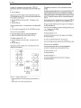
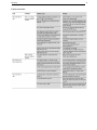
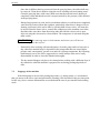
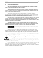
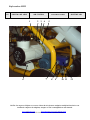
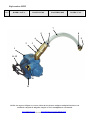
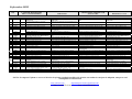
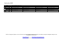
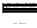
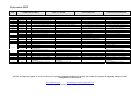
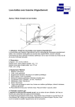
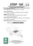
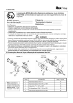
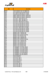
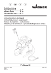
INSTRUCTIONS Delta-Mini www.utiform.com departamento.té[email protected] Tfno. +34 96 570 29 82 Fax: +34 96 570 29 83 Mini Pump 1 Introduction Please read this User Manual carefully before using your new Mini pump. It is essential that the operating personnel become thoroughly familiar with all the functions and workings of this machine in order to avoid errors that could lead to the machine being damaged. We recommend thorough care and careful handling of the machine so that your Mini will have a long working life and not experience any breakdowns. Please send the guarantee request form that you were given when you purchased your new Mini to the factory without delay. You will then receive your certificate of guarantee and will be added to our client base. This will enable you to receive information about new products and all the possible uses of the Mini. If any problems were to occur, or if you need to order spare parts or request the help of our Customer Service, please either contact your nearest UTIFORM dealer, or contact us directly. If you wish, we can provide you with the name of your nearest dealer. The User Manual has an appendix with a detailed list of all the spare parts for the Mini. In order to avoid mistakes in deliveries please always indicate the exact name and part number from this list when making your orders. To avoid possible damage to the machine caused by using spare parts that are either defective or of poor quality, you should only use original UTIFORM wear and spare parts that have been tested appropriately. Please fill in the form below so that you know the basic characteristics of your machine and have these easily at hand for when you need to order spare parts. You will find the data to fill in here on the plaque with the machines characteristics. MINI ............................................. Machine number Type...................................... Engine head Number................................. We reserve the right to carry out any technical modifications to the machine that lead to its improvement although not specified in this manual. User Manual Number ........................................................................................................ We wish you every success with your new Mini pump. Mini Pump 2 1 Technical description 4 2 Operating mode 4 3.1 Technical Information Standard model 5 5 4.1 General safety guidelines Safety 6 7 4.1.1 4.1.2 4.1.3 4.1.4 4.1.5 4.1.6 Designated use Indication of danger Security in the workplace Safety rules for conveyers and spraying machines Protective devices for personnel Other suggestions 7 8 8 9 9 9 Start-up 10 10 10 10 10 5.10 5.11 5.12 Installation of the machine Electricity supply point Water supply point Product hose placement and lubrication Connection of air hose and spraying lance Checking the rotation direction Loading of air into the water regulator Adjustment of water regulator Pressure test of the perpetual screw pump (stator- sleeve) Amount of water required Machine start-up Spraying 6.1 Speed Variator Commissioning of the ATV 18 variator 3 4 5 5.1 5.2 5.3 5.4 5.5 5.6 5.7 5.8 5.9 10 10 11 11 11 12 12 13 Interruptions in Operation 13 13 17 20 Brief interruptions Long interruptions in work and completion of work Stoppage of the machine 20 20 21 8 Service and maintenance 22 9 Faults and corrective actions 23 10 Accessories 25 11 EC Declaration of Conformity 26 6 7 7.1 7.2 7.3 Mini Pump 3 12 Appendix 12.1 Combined diagram 12.2 Water system 12.3 Air system 12.4 Water pump 12,5 Compressor delta 75 12.6 Straight spraying gun and hoses 12.7 Fittings 12.8 Circuit board 12.9 Mini 220 V electronic control panel distribution 12.10 Mini 220 V electronic control panel connection. 12.11 Mini 220 V electronic control panel variator outlet. 12.12 Mini 220 V electronic control panel power diagram. 12.13 Mini 220 V electronic control panel manipulation diagram. 12.14 Mini 220-380 V electronic control panel distribution. 12.15 Mini 220-380 V electronic control panel connection. 12.16 Mini 220-380 V electronic control panel variator outlet. 12.17 Mini 220-380 V electronic control panel product outlet. 12.18 Mini 220-380 V electronic control panel power diagram. 12.19 Mini 220-380 V electronic control panel manipulation diagram. 28 Mini Pump 1 4 Technical description The Mini forms part of UTIFORM’s long trajectory in manufacturing mixing pumps for bagged material. These machines mix the material to a homogenous consistency while also allowing the hydro-mechanical transport of the material by means of a perpetual screw pump. The Mini pump is loaded with bagged material. Compared to the traditional systems, this pump has a more functional structure, while requiring less maintenance, and is particularly suitable for mixing and conveying prepared mortars and dry premixed material such as adhesive for tiles, structured mortars and plaster as well as mortar for plastering. The Mini is ideal for those situations where an immediate availability of material is more important than the pumping capacity. The machine itself comprises a dry material deposit which has the mixing tube connected to it at the bottom. At the top of the dry material deposit there is a motor reductor with its corresponding cover which activates the mixing beater by means of a stop shaft. The transversal bar of this then activates the perpetual screw of the mixing pump eccentric situated at the bottom of the mixing tube. The mounted perpetual screw pump comprises an auto adjustable and fixed (stator) cover for the perpetual screw, and a perpetual screw for the eccentric (rotor) made of a material highly resistant to wear and tear. With this system the nuisance of having to adjust and retighten the stator screw is avoided. To avoid damage during transport the machine’s chassis is installed with both the electronic control panel and other control devices as well as the valves to regulate the exact amount of water in the mix. 2 Operating mode The operating mode is similar to that of a mixing pump. The dry material deposit is loaded with the bagged material. The dry material falls into the dry area of the mixing tube and the motor reductor makes the mixing beater turn. The mixing beater has spiral screw threads which bring the dry material to the wet area of the mixing beater. A small joint provides a continuous jet of water which can be regulated with precision. The dry material and the water are mixed together in the shortest possible time and are transformed into a mass which can be pumped and is ready to use. The single screw pump installed at the bottom of the deposit transports the mixture through the flexible pipe with a pumping capacity of up to 20 l/min, and brings it to the projecting lance. The pump can be activated or deactivated by means of a remote pneumatic control installed in the projecting spout. The pressure control valve in the water measuring device makes the machine stop if the water pressure is insufficient. To enable ease of transport the machine has two rubber-encased wheels that turn and two fixed ones, which makes it easier to manoeuvre on a building site. Mini Pump 3 5 Technical Data Machine type ........................................................................DELTA - MINI Power of motor.....................................................................2.2 Kw three-phase head motor Electrical connection ............................................................230 V./50 Hz. Network connection .............................................................CEE 2P+T 16 A./6h. Control connection ...............................................................48 V./50 Hz. Current..................................................................................16 A. Type of spiral pump(sleeve).................................................(according to client preference) Capacity................................................................................5 to 20 l/min. (*) Pumping pressure .................................................................max.15 bares max. (*) Pumping distance .................................................................up to 15 mts. (*) Air compressor .....................................................................170 l/min. approx. Maximum air pressure..........................................................3.5 bars Required water pressure .......................................................3 bars Water coupling .....................................................................Geka Loading height......................................................................1050 mm. Width....................................................................................590 mm. Length...................................................................................1280 mm. Total height ..........................................................................1410 mm. Weight ..................................................................................Approx.155 Kg. (*) Depending on the type of material, consistency and length of conveying hose. 3.1 Standard model - 1 Membrane compressor, approx. 170 l/min. 1 230 V wet-rotor pump 1 Tool box 1 25mm straight projecting lance with spout. 1 Standard mixer 1 Stator (shirt) of choice 1 Rotor 1 Set cleaning tools (scraper and restorer) 1 Nozzle cleaning tool Wrenches (2 flat wrenches, 1 ring wrench, 1 pressure regulator /socket wrench, wrench for switch board) 2 Rubber cleaning balls 35 mm. 10-metre material conveying pipe, 25 mm diameter with coupling. 10-metre air pipe 3/8” with coupling. 5-metre water pipe 3/4” with absorption valve. 25 metres of electric piping 5x2’5 mm2 with base. 1 CEE Conformity Certificate. 1 6-month guarantee. 1 User manual and list of machine parts. Optional: - 1 pressure checker with gauge Additional piece for hopper to increase capacity. Full insufflation hood and bore. Mini Pump 4 6 General safety guidelines In order to make working with the Mini easier and safer we have listed here the most important safety regulation which should be followed to avoid any danger when working with the machine. INSTRUCTIONS FOR USE 1.- The MINI is designed to mix, convey and spray mineral building materials. The machine should only be used for the tasks for which it has been designed and the manufacturer’s User Manual should be followed at all times. 2.- The machine should only be used by experienced personnel (machinery operators) who have been previously instructed in the operating procedures and maintenance. They should be familiar with its workings and have read the User Manual thoroughly. 3.- The machine should be positioned firmly on the site and secured so that there are no unwanted movements. 4.- Machines that run on electricity need to be connected to a suitable feeder socket (one that has a protector switch in the case of defective electrical currents). 5.- The machine must be installed at a safe distance from high scaffolding and should be protected against any possible damage from falling objects. 6.- The conveying pipes must be fixed in such a way that any strain is absorbed by adequate filtration points (hooks for pipes). This is especially important for pipes in a raised position. 7.- The conveying pipes must also be positioned in such a way that no damage will occur. If they cannot be laid completely straight and must be laid with a curve, then the radius of the curve should be no less than six times the exterior diameter of the pipe. 8.- Use only original UTIFORM high pressure pipes for materials. These come with built in couplings. 9.- Before switching on the machine you should check that nobody will be put in danger by doing so. 10.- When the machine in used you must check that the conveying pipe has sufficient prelubrication, that is, that the material used can be easily pumped and that there are no points left unsealed at the joints of the pipe. 11.- Both in the case of activation or failure of the security devices, the machine must be stopped until the problem has been eliminated. 12.- Before opening the conveying pipe system or any other component of the conveying system that is under pressure, you must first check that there is no pressure in the system. 13.- Blockages in the pipes must be eliminated following the instructions in this User Manual. The person in charge of carrying out this operation must position himself where he will not be reached by spraying material. Nobody else should be in the surrounding area. Mini Pump 7 14.- Security and accident prevention devices should not be removed or modified, and these must be handled correctly. 15.- Whenever the machine is being cleaned or repaired it should be turned off at the mains switch, otherwise the pneumatic remote control could start up the main motor by itself. 16.- Before starting the machine the operating safety of this must be checked. As soon as any faults are detected, or even indications of these, they should be eliminated immediately and the personnel supervisor notified. In the case of finding any faults that may endanger operating safety, use of the machine must be interrupted. 17.- If an accident happens as a result of not having respected the safety measures given here, or the safety measures in the work place as established by professional associations or by the insurance company with relation to civil responsibility or your country’s legislation, or caused by negligence, then the legislator will hold the machine operator responsible or, in the case that this person could not be held responsible due to lack of training or basic knowledge, then the personnel supervisor will be held responsible. For all these reasons, when you are working with the Mini, please do so with caution and bear in mind the safety measures that apply in each case (safety measures for the association of construction professionals relative to conveyors and spraying machines). Below you will find some brief safety instructions to be followed for the correct use of this machine onsite. 4.1 Safety 4.1.1 Designated use This machine has been designed and built for safe operation in accordance with current technological levels. However the machine may present a danger if it is used inadequately or for an unintended use or one not included in this user manual. Pay special attention to this symbol in this chapter! Mini Pump 8 4.1.2 Indication of danger Actions that require particular care and precaution to be taken have been marked with this symbol: This symbol is used to indicate all those jobs in which there may be danger to the health of personnel if the parts are handled incorrectly. Please pay close attention to the instructions and work with extra care. You should also follow the general indications on security and for the prevention of accidents with reference to the building sector. This symbol is used to indicate all those procedures where it is obligatory to have first read the user manual. An example of one of these procedures is when it is necessary to uncouple parts of the machine. In this case there is the risk that the material is still under residual pressure and it could splash your eyes, so it would be necessary to wear protective glasses. This symbol is used to indicate all those tasks in the user manual that could cause damage to objects. WARNING! 4.1.3 Security in the workplace x The machine must be checked for visible damage before each use. Particular attention should be made to the electronic feeder cables, plugs, couplings and pipes. x Work to the electric panel of the machine should only be carried out by specialised technicians or by an electrical expert, and always in accordance with the technical rules on electricity. x The connection to the mains must always be protected by means of a protector switch in case there is a fault in the current (current transformer for building sites). x Before correcting faults or carrying out maintenance or cleaning the machine, make sure it is turned off at the mains switch. Unplug the machine from the mains and for greater security hold the mains switch in place with a padlock. x Special attention must be paid to the following points: WARNING! - x The protective grid on the material deposit must be screwed tightly shut! The mixing tube, the motor cover and feeder motor must be securely attached to the machine! All work carried out using the material pumping machine (for mortar or plaster) should be in accordance with the general regulations on safety and accident prevention in the building industry. Mini Pump 9 4.1.4 Safety rules for conveyers and spraying machines. x This type of machine should only be used by qualified and responsible personnel (foreman) who have been specifically appointed by building company. They should be instructed in the handling and maintenance of the machine and be familiar with all its workings. x The machine must be installed where it will be stable and secured against any accidental movement. x Machines running on electricity must be connected to a special socket (normally a current transformer for building sites), in accordance with paragraph 55 of regulation VDE 0100/5. x The machine must be installed where it is in no danger from falling objects or else shielded with a protective material. The pipes must be laid in such as way that they will not be damaged. x If the safety devices on the machine either activate or fail to work correctly, the machine should be stopped until the problem has been corrected. x Before opening the joints on the conveying pipes or other parts of the system that are under pressure, the foreman must make sure there is no pressure in the system. x Blockages should be eliminated following the indications in the instructions for use. The person in charge of eliminating blockages must position himself in such a way that he will not be hit by the mortar coming out. There should be nobody else nearby when this task is being carried out. 4.1.5 Protective devices for personnel x The building company must provide personnel with adequate means for individual acoustic protection if the noise in the workplace reaches over 85 dB(A). x All personnel must use this acoustic protection for levels of 90 dB(A) or higher. x Protective glasses must be provided for the task of eliminating blockages. Protective glasses are considered to be glasses with a frame that meets part 2 of the DIN 58 211 regulation and lenses that meet page 5 of the Din 4647 regulation. 4.1.6 Other suggestions x It is recommended that only original spare parts and accessories are used. x No modifications should be made to the original machine. Mini Pump 10 5 Start-up 5.1 Installation of the machine The Mini pump must be installed on the flattest surface possible and secured by activating the two wheel brakes. The compressor and driving motor connectors must be connected to the electricity sockets supplied for this purpose on the electronic control panel. There can be no confusion because the connecting sockets and cable lengths are different. The main motor switch must be placed in the “0” position. The additional cleaning connection and release valves on the water valves must also be closed. Also check that the material stop valve is closed. 5.2 Electricity supply point Use only a special three-pole 3*2.5 mm2 section and 1 KV electricity cable for construction work. In order to avoid voltage losses, the electricity cable must always be unreeled completely! To ensure proper operation of this machine, it is very important that the power supply is 230 V at the machine’s power supply inlet. WARNING! 5.3 Water supply point The water hose, which is resistant to creases and high pressures, must be completely unreeled; it must have a minimum interior diameter of 3/4”. It must be connected to a suitable tap and any air inside the hose must be eliminated. The water pressure gauge needle must indicate a minimum pressure of 3.5 bars; this can be achieved by installing a pre-fitted pump to increase water pressure between the water supply network and the machine. 5.4 Product hose placement and lubrication The Mini pump is equipped with an original factory-supplied hose fitted with quickfitting couplings. The hose distance must be as short as possible. We recommend moistening or lubricating the hose interior to prevent it from becoming blocked. To do so, a coupling is connected to the machine to establish the hose cleaning connection; the hose is filled with water and the water is allowed to run out of the end. 5.5 Connection of the air hose and spraying lance Unreel the 3/8” air hose, which is resistant to pressure and creases, next to the product hose and connect it to the machine air outlet. When this is done, the compressor hose must be connected to the air pressure gauge and the connection plug to the corresponding electricity socket on the electronic control panel. The spraying lance is connected to the other end of the air hose and the air spray gun is adjusted (the diameter of the product hose nozzle is equal to the distance of the air gun on the spraying lance). 5.6 Checking the rotation direction - Lower the head motor and remove the beater. Put the motor back in its vertical position. Disconnect the water hose from the mixing tube. Activate the head motor, compressor and, finally, main switch (red and yellow). The motor must rotate in the direction indicated by the arrow on the protective part of the motor fan (anti-clockwise, i.e. to the left). Mini Pump 11 - If it rotates in the wrong direction, the phases on the lower part of the electricity input plug must be rotated. WARNING! If the plug is changed or a main cable extension cable is not used, check the rotation direction again. 5.7 Loading of air into the water regulator Disconnect the water hose from the mixing tube and leave it in the bucket. Press the electrovalve release button until no bubbles appear in the flow metre. 5.8 Adjustment of the water regulator While the water valves are being loaded with air, regulate the desired amount of water by pressing the electrovalve release button. Open the water control valve until the buoy reaches approximately 400 l/h. Note: The amount of water actually required by the product that is being mixed is regulated later by the machine during operation until the desired product consistency is obtained. 5.9 Pressure test of the perpetual screw pump (stator- sleeve) The Mini pump is equipped with a maintenance-free pumping element (according to customer’s request); its pumping pressure is optimally adjusted to the conditions at the work site (according to both material consistency and composition and hose length and diameter). Normally, the pumping elements not requiring maintenance are used until they reach their limit of wear, i.e. until the supply flow is reduced substantially or the consistency of the material ranges between thick and fluid. In these cases, the pump elements must be replaced. If the wear of the maintenance-free set of pumps has to be controlled or if retensionable sets of pumps are used, pump pressure is calculated as follows: WARNING! The water hose is connected to the upper connection of the mixing tube, the pump motor is lowered and the beater is removed from the mixing chamber. Activate the electrovalve release button and let water enter the mixing chamber until it covers the top of the perpetual screw (rotor). In order to ensure that the water level in the mixing chamber does not continue to rise while the pressure is being adjusted, disconnect the water hose from the mixing tube. The process described below would be performed in the case with the option of the pressure regulator: After placing the mixer back in the tube and repositioning the head motor fixed with the safety valve, connect the hydraulic pressure regulator to the sleeve outlet with the release valve open. After briefly starting the head motor (approximately 1 or 2 seconds), the air is eliminated from the pressure regulator. The release valve is then closed and the head motor is reactivated for a few seconds; at the same time, monitor the oscillation of the pressure valve indicator needle. The upper oscillation value of the pressure valve corresponds to the regulated pressure of the pump! Mini Pump 12 Hydraulic check rule: if flat plaster is applied using a Dn 25 pipe measuring up to 10 metres in length, the pressure valve must read 15 bars. 5.10 Amount of water required Immediately before starting the work, make sure that sufficient water is in the mixing chamber (covering the rotor head). If this is the case, introduce water into the mixing chamber following the instructions described in the previous point; if this is not done, dry material may penetrate the sleeve. WARNING! : Failure to comply with the foregoing will lead to premature wear and tear or even breakage of the sleeve in a fraction of a second when the pump motor is started with dry material and without water. 5.11 Machine start-up Activate the main switch and start the pump motor by pressing the green start button. Set the motor speed using the speedometer inside the control panel display. Regulate the speed according to the machine’s input voltage; if the voltage is low (around 200-210 V), we recommended setting the speed to approximately speed position Nº 4 i.e. 40 Hz. working speed. Use the control valve to regulate the consistency of the material by adjusting the water flow until you achieve the desired working conditions. Stop the main motor and connect the product hose to mixing tube outlet. Control the consistency of the material at the end of the hose. With the machine stopped, connect the spraying lance to the product hose. Regulate the water level until you achieve the desired consistency. WARNING! : When regulating the amount of water, bear in mind that any changes in consistency due to hose length will only be reflected in the corresponding delay that occurs in the spraying lance. Mini Pump 5.12 13 Spraying The material (mortar or plaster) is applied continuously and horizontally, line by line. The prior condition necessary for continuous work is that there must be sufficient material in the hopper at all times. The level of dry material in the hopper must never fall below the perpetual screw pump axle. Continuous spraying may be achieved by using the correct rubber nozzle on the spraying lance (diameter 14 mm.). The distance between the spraying lance and the wall must be maintained at between 15 and 30 cm. The pump must be placed in a position that ensures the shortest possible hose length (10 metres). Hose extensions produce greater pressure in the transportation of the hose and consequently greater wear and tear of the pump parts. 6 Speed Variator This machine incorporates a speed variator or single-phase frequency converter (2.2 kW). The incorporation of this device on the Mini pump provides a machine input power of 230 V, allowing the pump’s main motor to operate at 230 V (three-phase). When the variator is powered on the power elements together with a certain number of control components are connected to the power supply. Do not touch these elements: they are extremely dangerous. After disconnecting the variator power, wait for one minute before reusing the device. This time corresponds to the electric discharge time constant of the condensers. Mini Pump 6.1 14 Commissioning of the DF-DV51 variator Mini Pump 15 Mini Pump 16 Mini Pump 17 Mini Pump Fault correction 18 Mini Pump 19 Mini Pump 20 7 Interruptions in Operation 7.1 Brief interruptions In order to transfer the machine from one place to another, simply disconnect the machine using the spraying lance cut-off valve. This will stop the head motor automatically. Turn off the main switch and stop the material conveyor so that no moisture penetrates the dry material hopper. WARNING! : Remember that in the event of work interruptions during operation, the spraying lance must always be placed with the material nozzle facing downwards, otherwise the material that continues to run out will obstruct the air diffuser. 7.2 Long interruptions in work and completion of work In the event of interruptions in work that exceed material setting times (end of spraying), the following procedure may be performed to clean the mixing chamber and material hoses thoroughly: - Stop the head motor by placing the switch to the “0” position. - Remove the beater from the mixing tube and replace it with the cleaning tool. - Briefly start the head motor and various times and then introduce the cleaning scraper in the mixture tube. This will eliminate material remains deposited in the mixing tube and allow them to be pumped through the product hose. - Check that the material hose has no pressure. To be safe, disconnect the hose (look away and use protective glasses!) from the pump outlet. - After removing the cleaning tool, clean, dry and replace the mixture tree. Dry material may stick to the beater (mixer) if this is moist when activated and may cause faults. - Remove the rubber nozzle from the spraying lance and wash it thoroughly with water. - Connect the cleaning adapter to the product hose and introduce the rubber ball under pressure. This ball is pressurised through the hose by the thrust of the water, thus cleaning the hose. The rubber ball remains trapped in the spraying lance diffuser. - After closing the cleaning connection, disconnect the spraying lance from the hose and then remove the hose from the cleaning connection. WARNING! : In order to prevent foreign bodies from entering the hose, connect both hose end couplings after you have unreeled the hoses. This will prevent faults caused by foreign bodies from occurring. Mini Pump 21 - Once the air diffuser has been removed from the spraying lance, the rubber ball may be removed. Clean the air diffuser using the nozzle cleaning tool and running water. Clean the spraying lance with water. Make sure that the material nozzle housing is completely clean and that the nozzle is not pressurised by the pressure of the material in the spraying lance. - During longer pauses in work, and as a minimum whenever work has been completed, water must be removed from the regulator, particularly when there is danger of frost forming (cold areas); this can be done by opening both release valves. Air must also be injected into the water valves; connect the compressor to the machine water inlet, disconnect the water hose from the mixing tube and with the release valves open, inject air using the electrovalve release button. The compressor is activated using the main switch. WARNING! : By removing water in both summer and winter you will have no unpleasant surprises due to frost! 7.3 - Particularly when working with smooth plaster, clean the pump outlet at least once a day; otherwise material may be deposited in the pump outlet that can cause higher pressure and, consequently, greater wear and tear of pump components. By loosening both fastener screws, the sleeve support device on the mixture tube can be easily disassembled in order to clean the chamber thoroughly. - The dry material hopper only has to be cleaned when working with a different class of dry material or when the machine is prepared for use during prolonged periods of time. Stoppage of the machine If the Mini pump is not used for prolonged periods, e.g. during winter, we recommend that you unscrew the sleeve rotor and perform the cleaning work described in the previous point. In this way, sleeve contour deformations are avoided and the rotor is prevented from becoming stuck. Mini Pump 8 22 Service and maintenance Make sure that the machine is not turned on accidentally when maintenance work and repairs are being performed (disconnect the current entry). The Mini pump has been built in such a way that it requires only minimum maintenance. However, in order to ensure perfect operation, the mixing tube, beater and material hopper must be free of hard material remains at all times. The electronic control panel must be kept dry and free of dust inside. Whenever necessary, remove dust from the control panel using a vacuum cleaner and after disconnecting the pump from the mains. We do not recommend blowing compressed air since dust lifted as a result is deposited on the connection contacts and may render these unusable. The reducer motors are lubricated for their entire working lives. However, if any grease is expelled, it must be replaced with ENERGREASE or a similar lubricating substance. If this happens, make sure not to exceed the specific amounts. Also, make sure that no material is stuck to the stator refrigeration wings or ventilator. The York absorption valve of the water hose from the drum to the machine must be cleaned daily before starting work and the pressure reducer filter must be cleaned once a week; in order to perform this last operation, use the special valve supplied with the machine. WARNING! : When assembling the filtering deposit, make sure that the ring seal is correctly positioned. Whenever necessary, use a damp cloth to clean the water metre indicator tube. If the indicator tube has turned dark in colour due to interior adhesions, remove the tube by loosening both joint screws and clean it inside using a cloth. Never use a metallic brush or similar device! In order to ensure that the air diffuser can move freely inside the spraying lance tubing at all times, grease this slightly after cleaning. Before performing any maintenance or cleaning work on electrical equipment, remove the plug from the mains. From time to time, remove the electrical connectors from the control panel and apply a little grease to the contacts. This will ensure the proper functioning of the connectors and prevent the contacts from burning. Remove and shake the filter disks on the extraction side of the membrane compressor and on the other side at least twice a week when cleaning the interior and every 14 days when cleaning the exterior. In this respect, make sure that the filters with thick soft surfaces are placed outwards and the thin hard surface filters inwards. Mini Pump 9 23 Faults and corrective actions Faults in the Mini pump can be eliminated very simply by performing a small number of operations. When eliminating these faults, it is essential that you comply with the following rules: 1. Before opening the control panel door, disconnect the machine from the mains! 2. Whenever working with moving parts of the machine, turn off the main switch or remove the plug from the power supply socket! 3. Work on the electronic control devices and valves must only be performed by specialised service personnel! FAULT CAUSE ELIMINATION Machine does not start No power supply Check electricity cable and electric connectors. Check 16 A. delayed-action fuses in the main circuit board at the work site. Switchgear Turn the black buttons on the control panel. The machine works for short periods and then stops. Insufficient water pressure The hose is blocked. Insufficient water supply. The main motor stops The thermal protection of after the machine is the variator has been started. activated due to high consumption by the motor The machine stops during operation or cannot be started from the spraying lance after a pause in work. Use other water supply points with larger transversal supply sections or use a water barrel with pump. Check the input current voltage. Recommended voltage: 230 V. Pump blocked by material remains. Disassemble the maintenance perpetual screw sleeve, dismantle, clean and reassemble. Pump blocked due to use when dry. Control the water input in the mixing tube and if necessary loosen the perpetual screw using the rotating tool and start the pump with sufficient water. Re-establish the electricity supply and start the machine using the pump control. Power cut No water Blocked air diffuser The water level rises in the mixing tube when the machine is Increase the water supply to at least 3 bars and if necessary use a pump to increase pressure. Check the water supply hose (diameter 3/4”) with respect to the narrow transversal sections (e.g. creases) Incorrect rotation direction Too much water. Re-establish the water supply and start the machine using the pump control. Stop the machine using the pump control and clean the air diffuser thoroughly using the piquera or check for any obstruction in the air hose. Change the position of the manual phase invertor on the electronic control panel. Mini Pump 24 working. Regulate the water slowly by reducing the water level until achieving the desired consistency. The parts of the pump are worn. The consistency of the material is too liquid or varies at irregular intervals. The material hose is blocked. Not enough dry material is being fed into the pump. Excessive water affluence. With free maintenance pumps, assemble new parts and if necessary use a pump with a greater supply pressure. Eliminate any obstructions in the hose. Refill the material tank with dry material (the level of dry material must never be below the perpetual screw pump axle) Regulate the water slowly by reducing the water level. Material is stuck to the mixing beater. The water rises in the Faulty electrovalve. mixing chamber when the machine is not being used. The machine cannot Leaking air valve. be stopped using the pneumatic control and/or the Defective compressor. compressor does not stop during pauses in work. Badly set pressure valve (air pressure valve). Stop the machine using the main switch, lower the head motor, remove the mixing beater, clean, dry and reassemble. Unscrew the upper part of the electrovalve and remove it carefully, since it has pretensioned springs inside. Clean the control drill as well as the membrane and reassemble the electrovalve. Check the air tightness of the air hose and the connections and change defective parts. Check the pressure of the compressor on the pressure valve of the water input by connecting the compressor to this. If a minimum of 3 bars of pressure is not achieved, the compressor must be repaired at the Service workshop. Ask the Service workshop to check the operation of the pressure thermostat and reset this if necessary (start = 1.1 bars; stop = 2.5 bars) Mini Pump 10 25 Accessories You may extend the scope of application of the pump with original Mini pump accessories and thus improve the handling of your equipment. In numerous applications of the Mini pump, material is loaded by pneumatic conveyor equipment from either a static or pressurised silo. In these cases, an airtight insufflation hood is placed on the dry material recipient of the device in order to channel the dry material and also filter dust from the supplied air. The dome of the hood is capped by a large filter, and also has an inspection hatch that can be closed, as well as a rotating vaned probe with a socket for connecting the control cable for the pneumatic conveyor equipment for static silos, or a device for pressurised silos. Four eccentric locks are fitted to the sides of the machine, fastened by hooks under the profiled moulding of the machine’s material recipient, and which securely fasten the insufflation hood, rendering it fully dust-proof. You can find many more accessories and all necessary spare parts in our catalogue, including details of prices, tools and spare parts. Use only original spare parts and accessories for purchased equipment! Reproduction of the content of this publication or extracts from it is prohibited without our written authorisation. All technical data, drawings, etc. are protected by industrial property right legislation. We reserve the right to introduce technical modifications. Mini Pump 11 26 EC Declaration of Conformity Pursuant to Machinery Directive 98/37/EC, the Company: UTIFORM TECHNOLOGIES S.L. Pol. Ind. Las Maromas, Esq. C/ Francia y Irlanda 03160 ALMORADÍ (Alicante) SPAIN hereby states, under its sole and exclusive responsibility, that the manufacture of the machine Model : MINI Machine number ........................................................................... Description : Pumping machine for mixing bagged materials complies with the basic requirements of the Royal Decree 1435/92 (27-11-92) relating to Machine Safety, modified by Royal Decree 56/95 (20-01-95) and Royal Decree 1215/97 (18-0797), which establishes the minimum safety and health regulations for the use of works equipment by workers. Moreover, in line with the stipulations of the following EU directives: Directive 98/37 CEE (22-06-98) regarding the approximation of legislations of member States on machines, which was modified by the directive 98/79 (27-10-98) Directive 89/336/CEE (19-02-73) regarding the approximation of legislations of the member States, about electromagnetic compatibility, which was modified by the directive 92/31/CEE and 93/68/CEE, incorporated to the Spanish legislation by means of the R.D. (Royal Order) 444/1994 (11-03-94), in which evaluation proceedings of conformity are established and the requisites of protection related to the electromagnetic compatibility of equipments, systems and installations, modified by the R.D. 1950/1995 (01-12-1995). Directive 89/336/CEE (19-02-73) regarding to the approximation of legislations of the member States, about sound emissions in the environment given to the use of machines in open air. Concerning Directive 98/37/CE, the self declaration has been carried out, being the machine in conformity with dispositions and requisites of the following European Norms: EN 292-1; 1991. - Security of machines. Basic concepts, general principles for the design. Part 1: Basic terminology, methodology. EN 292-2; 1991. - Security of machines. Basic concepts, general principles for the design. Part 2: Principles and technical specifications. (Modification A1) EN 294:1992. - Security of machines. Safety distances to avoid reaching dangerous zones with upper members. Likewise, there are in conformity with the following Norms: EN 60204-1:1997.- Safety of machines. Electric equipment of the machines. Part 1: General requirements EN 418:1992.- Safety of machines. Equipment for emergency stop, functional aspects. Design principles Mini Pump 27 Concerning Directive 89/336/CE, the self declaration has been carried out, being the machine in conformity with dispositions and requisites of the following European Norms: EN 50081-1:1992. - Electromagnetic compatibility. Generic emission Norm. Part 1: Residential, commercial and industry EN 50082-1:1992. - Electromagnetic compatibility. Generic immunity Norm. Part 1: Residential, commercial and industry This Certificate of Conformity shall be limited in terms of responsibility for testing, if the retailer or distributor on its own account and at its own risk, and with our express authorisation, makes changes to the machines, uses the machines for other purposes than those specified for them or for work in a country outside the territory in which the EU regulations 98/37 CEE are applicable, or in the case of repair by non-authorised third parties, with assembly of parts and wear and tear. Almoradí, …............................ Miguel Ángel Peco Industrial Technical Engineer Mini Pump 28 Appendix 12 12.1 Combined diagram 12.2 Water system 12.3 Air system 12.4 Water pump 12,5 Compressor delta 75 12.6 Straight spraying gun and hoses 12.7 Fittings 12.8 Circuit board 12.9 Mini 220 V electronic control panel distribution 12.10 Mini 220 V electronic control panel connection. 12.11 Mini 220 V electronic control panel variator outlet. 12.12 Mini 220 V electronic control panel power diagram. 12.13 Mini 220 V electronic control panel manipulation diagram. 12.14 Mini 220-380 V electronic control panel distribution. 12.15 Mini 220-380 V electronic control panel connection. 12.16 Mini 220-380 V electronic control panel variator outlet. 12.17 Mini 220-380 V electronic control panel product outlet. 12.18 Mini 220-380 V electronic control panel power diagram. 12.19 Mini 220-380 V electronic control panel manipulation diagram. EXPLODED VIEW Delta-Mini www.utiform.com departamento.té[email protected] Tfno. +34 96 570 29 82 Fax: +34 96 570 29 83 Enfoscadora MINI 12.1 PLANO GENERAL 24 25 1 COMBINED DIAGRAM ALLGEMEINES SCHAUBILD 2 PLAN GÉNÉRAL 3 4 23 21 22 5 20 6 19 7 8 18 9 10 17 16 15 14 13 12 11 NOTA: La empresa Utiform se reserva el derecho de efectuar cualquier modificación técnica con tendencia a mejorar la máquina, aunque no esté contemplada en esta manual. www.utiform.com departamento.té[email protected] Tfno. +34 96 570 29 82 Fax: +34 96 570 29 83 Enfoscadora MINI 12.1 Nº COMBINED DIAGRAM PLANO GENERAL Ref. Uds. Descripción Description 1 1 MOTOREDUCTOR 3 Kw. 400 V. 50/60 Hz. 75003 1 CAMPANA MOTOR 30 MM. 45009 Versión Mini 220 V. 36007 1 MANG. ELECTRICA 5x2'5 37000 1 CLAVIJA 16 A. 3P+T/6h. Versión Mini 220-380 V. 36022 1 MANG. ELECTRICA 7x2'5 37008 1 CLAVIJA AEREA 16 A. 7P/9h. 230 V. 50/60 Hz. 2 3841002030 1 CIERRE TUBO MEZCLA C/SEGURO 40 MM. FASTENER MIXING TUBE WITH SAFETY 40 MM. 3 4 45056 41170 1 1 REJILLA TOLVA DELTA-MINI TORNILLO C/ARANDELA D6921 M8x16 TRAMO MANG. AIRE 3/8" COMPRESOR-MAQ. HANDY VALVULA ANTIRETORNO 1/4" ACOPL. GEKA R. INT. 3/4" TUERCA TENSOR CAZOLETA M16 DIN 6331 BRIDA UNION TUBO MEZCLA JUNTA TORICA 100x5 -BRIDA UNIONTORNILLO CON OJO M16 CAMISA D4 MW PLATA-ECO ROTOR D4 MW PLATA-ECO ACOPL. SKK V 25 R. INT. 1 1/4" CURVA 45º M-H 1 1/4" CAZOLETA SALIDA MATERIAL MASTER/DELTA-MIX TORNILLO D931 M12x65 TUERCA AUTOBLOC. D985 M12 PASADOR DE ALETA 4x40 RUEDA MACIZA 260/85 BOMBA AGUA 230 V. PARO TOTAL COMPLETA COMPRESOR 230 V. 50 Hz. (1 ph) RUEDA GIRAT. C/FRENO 200/70 (27x60) BULON GRUESO RUEDA GIRAT. S/FRENO 200/70 (27x60) BULON GRUESO GRILL HOPPER DELTA-MINI SCREW D6921 M8x16 HOSE PART AIRE 3/8" COMPRESOR-MAQ. HANDY VALVE NON-RETURN 1/4" CUPPLING GEKA INT. THREAD 3/4" SCREW BRACKET BEARING M16 DIN 6331 CLAMP JOINT MIXING TUBE RING SEAL 100x5 -BRIDA UNIONSCREW M16 STATOR D4 MW SILVER-ECO ROTOR D4 MW SILVER-ECO CUPPLING SKK V 25 INT. THREAD 1 1/4" CURVE 45§ M-H 1 1/4" SHIELD MATERIAL OUTLET MASTER/DELTAMI SCREW D931 M12x65 39501 1 1 1 2 11 12 434091 77020 45075 45000 45046 31022 71011 72009 76010 32602 13 31020 1 41116 41213 41603 28200260085 2 2 5 6 7 8 9 10 14 15 16 1 2 1 1 1 1 2 17 39953 1 18 52426870 1 28264200070 1 28260200070 1 19 ALLGEMEINES SCHAUBILD Bezeichnung PLAN GÉNÉRAL Désignation GEARBOX 3 Kw. 400 V. 50/60 Hz. METAL BELL MOTOR 30 MM. MOTOR DECKHAUBE 30MM. MOTOREDUCTEUR 3 Kw. 400 V. 50/60 Hz. CLOCHE MOTEUR 30 MM. ELECTRIC CABLE 5x2'5 STROMKABEL 5x2'5 CABLE ELECTRIQUE 5x2'5 FICHE 16 A. 3P+T/6h. ELECTRIC CABLE 7x2'5 PLUG 16 A. 7P/9h. REF.741 STROMKABEL 7x2'5 CABLE ELECTRIQUE 7x2'5 FICHE 16 A. 7P/9h. REF.741 FERMETURE TUBE MELANGE AVEC SECURITE 40 MM. KUPPLUNG GEKA INNENGEWINDE 3/4" GRILLE TREMIE DELTA-MINI VIS AVEC RONDELLE D6921 M8x16 TUYAU AIR 3/8" COMPRESSEUR-MACHINE HANDY SOUPAPE ANTIRETOUR 1/4" RACCORD GEKA R. INT. 3/4" WHEEL 260/85 WATER PUMP 230 V. AUTOM. SHUT OFF SYSTEM COMPLET COMPRESOR 230 V. 50 Hz. (1 ph) BRIDE UNION TUBE MALAXAGE JOINT TORIQUE 100x5 -BRIDE UNIONVIS AVEC OEIL M16 JAQUETTE D4 MW ARGENT-ECO ROTOR D4 MW SILVER-ECO RACCORD SKK V 25 R. INT. 1 1/4" COURBE 45§ M-H 1 1/4" POCHE SORTIE MATERIEL MASTER/DELTA-MIX VIS D931 M12x65 ECROU AUTOBLOQUANT D985 M12 GOUPILLE D'EMPENNAGE 4x40 ROUE PNEUMATIQUE 260/85 POMPE EAU 230 V. ARRET TOTAL COMPLETE COMPRESSEUR 230 V. 50 Hz. (1 ph) WHEEL TURN. WITH BRAKE 200/70 (27X60) ROUE GIRAT. AVEC FREIN 200/70 (27x60) WHEEL TURN. NO BRAKE 200/70 (27X60) ROUE GIRAT. SANS FREIN 200/70 (27x60) STATOR D4 MW SILBER-ECO ROTOR D4 MW SILBER-ECO KUPPLUNG SKK V INNENGEWINDE 1/4" SICHERHEITSMUTTER M12 NOTA: La empresa Utiform se reserva el derecho de efectuar cualquier modificación técnica con tendencia a mejorar la máquina, aunque no esté contemplada en esta manual. www.utiform.com departamento.té[email protected] Tfno. +34 96 570 29 82 Fax: +34 96 570 29 83 Enfoscadora MINI 20 39907 1 30530024 1 21 22 23 24 25 30530025 1 39005 001031130 39043 1 1 1 TUBERIA AGUA MASTER/DELTA-MIX C/VALV. REG. CAUDAL CUADRO ELECTRICO DELTA-MINI 220 V+VARIADOR CUADRO ELECTRICO DELTA-MINI 220-380 V+VARIADOR CHAPA PROTECC. DELTA MINI CHASIS DELTA-MINI BRIDA SUPERIOR MOTOR DELTA-MINI WATER TUBING CPL. MASTER/DELTA-MIX WITH VALVE RE ELECTRIC BOX DELTA-MINI 220 V+VARIADOR ELECTRIC BOX DELTA-MINI 220-380 V+VARIATOR PROTECTION PLATE DELTA MINI CHASSIS DELTA-MINI CLAMP SUPERIOR MOTOR DELTA-MINI BLOCK SUSPENSION PASS FOR MIXINGTUBE 46164 1 PASADOR TUBO MEZCLA MINI 001031130 1 TOLVA DELTA-MINI TUYAUTERIE EAU MASTER/DELTA-MIX AVEC SOUPAPE. REG. DEBIT TABLEAU ELECTRIQUE DELTA-MINI 220 V+VARIATEUR TABLEAU ELECTRIQUE DELTA-MINI 220-380 V+VARIATEUR PLAQUE PROTEC. DELTA MINI CHASSIS DELTA-MINI BRIDE SUPERIEURE MOTEUR DELTA-MINI CHEVILLE A ?ILLET GOUPILLE TUBEMELANGE NOTA: La empresa Utiform se reserva el derecho de efectuar cualquier modificación técnica con tendencia a mejorar la máquina, aunque no esté contemplada en esta manual. www.utiform.com departamento.té[email protected] Tfno. +34 96 570 29 82 Fax: +34 96 570 29 83 Enfoscadora MINI 12.2 SISTEMA AGUA 5 WATERSYSTEM 4 3 WASSERARMATUREN 2 SISTÈME EAU 1 12 6.1 6.2 27 7 8 9 26 10 25 24 23 22 21 8 20 7 19 18 4 17 10 16 6.3 11 12 13 14 15 NOTA: La empresa Utiform se reserva el derecho de efectuar cualquier modificación técnica con tendencia a mejorar la máquina, aunque no esté contemplada en esta manual. www.utiform.com departamento.té[email protected] Tfno. +34 96 570 29 82 Fax: +34 96 570 29 83 Enfoscadora MINI 12.2 Nº SISTEMA AGUA Ref. Uds. 39907 1 32005 670115101 32502 1 1 1 4 45033 2 5 41101 41211 3 6.1 001025501 1 6.2 001025502 6.3 7 8 9 10 11 12 13 14 39032 45032 45030 45035 38202 309702 LPH-22 77003 77023 1 2 3 WATERSYSTEM Descripción Description TUBERIA AGUA MASTER/DELTA-MIX C/VALV. REG. CAUDAL 23 39509 1 24 25 26 77012 77023 45053 1 1 1 OLIVETA 1/2" ESPIGA R. EXT. 1/2" VALVULA REGULADOR CAUDAL 1/2" CODO 90º M-H 1/2" GALVANIZADO TUERCA METALICA DOSIFICADOR AGUA 1600 TORNILLO D933 M8x20 TUERCA AUTOBLOC. D985 M8 PLETINA TUBERIA AGUA MASTER (DOSIFICADOR) PLETINA TUBERIA AGUA MASTER (BLOQUE Al. VERTICAL) PLETINA TUBERIA AGUA (sencilla) ROSCA PLAST. DOSIF. 1600 JUNTA TORICA 28x3 -DOSIFICADORTUBO DOSIFICADOR AGUA 1.600 MANG. AGUA TRANSMETAL 14x20 MM. GRIFO PURGA 1/4" M-H CASQUILLO 22 MM. P/MANG ACOPL. GEKA P/MANG. 1/2" JUNTA ACOPL. GEKA BLOQUE Al. VERT. GRIFERIA AGUA MASTER MACHON REDUCIDO 3/4"-1/2" ELECTROVALVULA 42 V. REGULADOR PRESIÓN R 1/2" JUNTA ACOPL. GEKA ACOPL. GEKA R. EXT. 1/2" VALVULA ESFERA 1/2" M-H CURVA 45º M-H 1/2" BLOQUE Al. VERT. GRIFERIA AGUA MASTER ACOPL. GEKA R. EXT. 1/2" JUNTA ACOPL. GEKA PRESOSTATO AGUA MASTER-MIX 27 3821010 1 MANOMETRO 0-10 Dn 50 R 1/4" S/RADIAL 2 2 1 0.8 mts. 1 2 1 1 15 39509 1 16 17 18 19 20 21 22 32710 45018 45079 77023 77012 303604 32601 1 1 1 2 1 1 1 WATER TUBING COMPLETE MALE THREAD STEM BRASS 1/2" EXT. 1/2" WATER REGULATING TAP 1/2" BEND 90º M-H 1/2" GALVANIZED WASSERARMATUREN Bezeichnung SISTÈME EAU Désignation WASSERLEITUNGEN MASTER / DELTA-MIX MIT REGELVENTIL TUYAUTERIE EAU MASTER/DELTA-MIX AVEC SOUPAPE. REG. DEBIT SCHLAUCHTÜLLE 1/2" ZAPFEN A. GEW. 1/2" DURCHSATZ DOSIERVENTIL 1/2" OLIVETA 1/2" CHEVILLE R. EXT. 1/2" SOUPAPE REGULATEUR DEBIT 1/2" COUDE 90º M-H 1/2" GALVANISE CODO 90º M-H 1/2" GALVANIZADO SCREW METAL WATER METER 1600 SCHRAUBE METALL FÜR WASSERDOSIER 1600 ECROU METALIQUE DOSEUR EAU 1600 SCREW D933 M8x20 SELF-BLOCKING SCREW D985 M8 SCHRAUBE DIN 933 M8x20 MUTTER SELBSTHEMMEND DIN 985 M8 TAP SET FLANGE TILE MASTER 2 PIECES HALTERUNG 2-TEILIG TAP SET FLANGE TILE MASTER 2 PIECES TAP SET FLANGE TILE MASTER 2 PIECES VIS D933 M8x20 ECROU AUTOBLOQUANT D985 M8 PLATINE ROBINETTERIE EAU MASTER 2 PCS. (DOSEUR) PLATINE ROBINETTERIE EAU MASTER 2 PCS. (BLOC VERT.) PLAT DOSEUR D'EAU (SIMPLE) FILET PLAST. DOSEUR 1600 JOINT TORIQUE 28x3 -DOSEURTUBE DOSEUR EAU 1.600 TUYAU EAU TRANSMETAL 14x20 MM. ROBINET PURGE 1/4" M-H SPANNHÜLSE 22 MM FÜR SCHLAUCH KUPPLUNG GEKA F. SCHLAUCH 1/2" JOINT RACCORD GEKA WATER DOSING MACHINE FLANGE TILE PLASTIC THREAD DOSIF. 1600 RING SEAL 28x3 -DOSIFIERWATER METER TUBE 1600 WATER HOSE TRANSMETAL 14X20 MM HANDLE 1/4" MALE - FEMALE SOCKET 22 MM. FOR HOSE COUPLING GEKA FOR HOSE 1/2" GEKA GASKET VERT. BLOCK WATER TUBING CONNECTING ROD REDUCED 3/4"-1/2" ELECTRIC VALVE 42 V. PRESSURE REGULATOR R 1/2" GEKA GASKET COUPLING GEKA EXT. THREAD 1/2" VALVE BALL 1/2" M-F CURVE 45º M-H 1/2" VERT. BLOCK WATER TUBING COUPLING GEKA EXT. THREAD 1/2" GEKA GASKET WATER PRESSURE SWITCH MANOMETER 0-10 D-50 R 1/4" HORIZONTAL HALTERUNG DURCHFLUSSMESSER PLASTIKGEWINDE DOSIER 1600 O-RING 28x3 -DOSIERDURCHFLUSSMESSER 1600 WASSERSCHLAUCH TRANSMETALL 14x20 MM ABLASSHAHN 1/4" M-H BAGUE 22 MM P/TUYAU RACCORD GEKA POUR TUYAU 1/2" DICHTRING KUPPL. GEKA ALUMINIUMBLOCK VERTIKAL FÜR WASSERLEITUNG MASTER REDUZIERSTšCK REDUZIERT 3/4"-1/2" ELEKTROVENTIL 42 V DRUCKREGLER R 1/2" DICHTRING KUPPL. GEKA KUPPLUNG GEKA AUSSENGEWINDE 1/2" KUGELVENTIL 1/2" M-V WINKELROHR 45º M-H 1/2" ALUMINIUMBLOCK VERTIKAL FÜR WASSERLEITUNG MASTER KUPPLUNG GEKA AUSSENGEWINDE 1/2" DICHTRING KUPPL. GEKA ÜBERDRUCKSCHALTER MANOMETER 0-10 D-50 R 1/4" BLOC VERT. ROBINETTERIE EAU PIEDROIT REDUIT 3/4"-1/2" ELECTROVALVE 42 V. REGULATEUR PRESSION R 1/2" JOINT RACCORD GEKA RACCORD GEKA R. EXT. 1/2" SOUPAPE SPHERIQUE 1/2" M-H COURBE 45º M-H 1/2" BLOC VERT. ROBINETTERIE EAU RACCORD GEKA R. EXT. 1/2" JOINT RACCORD GEKA PRESSOSTAT EAU MANOMETRE 0-10 D-50 R 1/4" S/RADIAL NOTA: La empresa Utiform se reserva el derecho de efectuar cualquier modificación técnica con tendencia a mejorar la máquina, aunque no esté contemplada en esta manual. www.utiform.com departamento.té[email protected] Tfno. +34 96 570 29 82 Fax: +34 96 570 29 83 Enfoscadora MINI 12.3 SISTEMA DE AIRE AIR SYSTEM 1 6 2 3 4 LUFTARMATUREN SISTÉME AIR 8 12 5 7 9 10 11 NOTA: La empresa Utiform se reserva el derecho de efectuar cualquier modificación técnica con tendencia a mejorar la máquina, aunque no esté contemplada en esta manual. departamento.té[email protected] www.utiform.com Tfno. +34 96 570 29 82 Fax: +34 96 570 29 83 Enfoscadora MINI 12.3 Nº 1 2 3 4 5 6 7 8 9 10 11 12 Ref. 32700 434091 32006 LPH-18 38000 52426870 41581 77012 32402 32707 77012 45054 SISTEMA DE AIRE Uds. 1 1 1 1 0.6mts. 1 1 1 1 1 1 1 Descripción MACHON 1/4" VALVULA ANTIRETORNO 1/4" OLIVETA 9 MM. ROSCA INT. 1/4" CASQUILLO 18 MM. P/MANG. MANG. AIRE 3/8"-10x16 mm. COMPRESOR 230 V. 50 Hz. (1 ph) PRENSASTOPA PVC M20x1.5 ACOPL. GEKA R. EXT. 1/2" TE 1/2" MACHON REDUCIDO 1/2"-1/4" ACOPL. GEKA R. EXT. 1/2" PRESOSTATO AIRE 1 NC R 1/4" AIR SYSTEM LUFTARMATUREN SISTÈME AIR Description CONNECTING ROD 1/4" VALVE NON-RETURN 1/4" REDUZIERSTÜCK 1/4" RÜCKSCHLAGVENTIL 1/4" PIEDROIT 1/4" SOUPAPE ANTIRETOUR 1/4" SOCKET 18 MM. FOR HOSE. AIR HOSE 3/8"-10x16 mm. COMPRESOR 230 V. 50 Hz. (1 ph) PVC PACKING GLAND M20x1.5 CUPPLING GEKA EXT. THREAD 1/2" T - SQUARE 1/2" CONNECTING ROD REDUCED 1/2"-1/4" CUPPLING GEKA EXT. THREAD 1/2" PRESSURE SWITCH 1 NC R 1/4" PRESSHÜLSE 18 MM FÜR SCHLAUCH LUFTSCHLAUCH 3/8"-10x16 mm KOMPRESSOR 230 V. 50 Hz. (1ph) STOPFBUCHSE PVC M20x1.5 KUPPLUNG GEKA AUSSENGEWINDE 1/2" TE 1/2" REDUZIERSTšCK REDUZIERT 1/2"-1/4" KUPPLUNG GEKA AUSSENGEWINDE 1/2" LUFTDRUCKWÄCHTER 1 NC R 1/4" BAGUE 18 MM P/TUYAU TUYAU AIR 3/8"-10x16 mm. COMPRESSEUR 230 V. 50 Hz. (1 ph) PRESSE-ETOUPE PVC M20x1.5 RACCORD GEKA R. EXT. 1/2" T-1/2 PIEDROIT REDUIT 1/2"-1/4" RACCORD GEKA R. EXT. 1/2" PRESOSTATO AIR 1 NC R 1/4" Bezeichnung Désignation NOTA: La empresa Utiform se reserva el derecho de efectuar cualquier modificación técnica con tendencia a mejorar la máquina, aunque no esté contemplada en esta manual. departamento.té[email protected] www.utiform.com Tfno. +34 96 570 29 82 Fax: +34 96 570 29 83 Enfoscadora MINI 12.4 BOMBA AGUA WATER PUMP WASSERPUMPE POMPE EAU 7 5 6 8 4 2 3 1 11,12 10 13 NOTA: La empresa Utiform se reserva el derecho de efectuar cualquier modificación técnica con tendencia a mejorar la máquina, aunque no esté contemplada en este manual. departamento.té[email protected] www.utiform.com Tfno. +34 96 570 29 82 Fax: +34 96 570 29 83 9 Enfoscadora MINI 12.4 BOMBA AGUA Nº Ref. Uds. - 39957 1 1 2 3 4 5 6 7 8 9 10 11 12 45605070 780103 32704 312106 32003 78004 38200 LPH-28 77005 77011 36012 DZ5CE015 41111 41702 41211 1 1 1 1 1 1 13 1 1 1 1 1 - 39953 1 1 2 3 4 5 6 7 8 9 10 11 12 525301 780103 32704 312106 32003 78004 38200 LPH-28 77005 77011 36012 DZ5CE015 41111 41702 41211 1 1 1 1 1 1 13 1 1 1 1 1 WATER PUMP Descripción BOMBA AGUA 230 V. PARO TOTAL COMPLETA BOMBA AGUA PERIFERICA 230 V. CODO 45º R.INT.1"-R.EXT.1" MACHON 1" LATÓN VALVULA ANTIRETORNO 1" OLIVETA 3/4" ESPIGA R. EXT. 1" ABRAZADERA SINFIN 20-32 MANG. AGUA 3/4"-19x27 mm. CASQUILLO 28 MM. P/MANG. AGUA ACOPL. GEKA P/MANG. 3/4" ACOPL. GEKA R. EXT. 1" MANG. ELECTRICA 4x1 PUNTA HUECA 1'5 mm TORNILLO D933 M8x25 ARANDELA D125A M8 TUERCA AUTOBLOCANTE M8 BOMBA AGUA 230 V. PARO TOTAL COMPLETA BOMBA AGUA 230 V. 50 Hz. CODO 45º R.INT.1"-R.EXT.1" MACHON 1" LATÓN VALVULA ANTIRETORNO 1" OLIVETA 3/4" ESPIGA R. EXT. 1" ABRAZADERA SINFIN 20-32 MANG. AGUA 3/4"-19x27 mm. CASQUILLO 28 MM. P/MANG. AGUA ACOPL. GEKA P/MANG. 3/4" ACOPL. GEKA R. EXT. 1" MANG. ELECTRICA 4x1 PUNTA HUECA 1'5 mm TORNILLO D933 M8x25 ARANDELA D125A M8 TUERCA AUTOBLOCANTE M8 Description WATER PUMP 230 V. AUTOM. SHUT OFF SYSTEM COMPLET 230 V. WATER PUMP COMPLETE BEND 45º INT. THREAD 1" - EXT. THREAD CONNECTING ROD 1" BRASS VALVE NON-RETURN 1" WATER HOSE 3/4" 19X27 MM SOCKET 28 MM. FOR HOSE. AGUA CUPPLING GEKA FOR HOSE 3/4" CUPPLING GEKA EXT. THREAD 1" ELECTRIC CABLE 4x1 SCHRAUBE D933 M8X25 WASHER D-125A M8 SELF-BLOCKING SCREW D985 M8 WATER PUMP 230 V. AUTOM. SHUT OFF SYSTEM COMPLET WATER PUMP 230 V. BEND 45º INT. THREAD 1" - EXT. THREAD CONNECTING ROD 1" BRASS VALVE NON-RETURN 1" WATER HOSE 3/4" 19X27 MM SOCKET 28 MM. FOR HOSE. AGUA CUPPLING GEKA FOR HOSE 3/4" CUPPLING GEKA EXT. THREAD 1" ELECTRIC CABLE 4x1 SCHRAUBE D933 M8X25 WASHER D-125A M8 SELF-BLOCKING SCREW D985 M8 WASSERPUMPE Bezeichnung POMPE EAU Désignation POMPE EAU PERIFERIQUE 400 V. PERIPHERISCHE WASSERPUMPE 230 V REDUZIERSTUECK 1" MESSING KUPPLUNG GEKA F. SCHLAUCH 3/4" KUPPLUNG GEKA AUSSENGEWINDE 1" STROMKABEL 4x1 VIS D933 M8x25 MUTTER SELBSTHEMMEND DIN 985 M8 COUDE 45º R.INT.1"-R.EXT.1" PILIER 1" LAITON SOUPAPE ANTIRETOUR 1" OLIVETA 3/4" CHEVILLE R. EXT. 1" TUYAU EAU 3/4"-19x27 mm. BAGUE 28 MM P/TUYAU EAU RACCORD GEKA POUR TUYAU 3/4" RACCORD GEKA R. EXT. 1" CABLE ELECTRIQUE 4x1 POINTE CREUSE 1'5 mm VIS D933 M8x25 RONDELLE D-125A M8 ECROU AUTOBLOQUANT D985 M8 POMPE EAU PERIFERIQUE 400 V. REDUZIERSTUECK 1" MESSING KUPPLUNG GEKA F. SCHLAUCH 3/4" KUPPLUNG GEKA AUSSENGEWINDE 1" STROMKABEL 4x1 VIS D933 M8x25 MUTTER SELBSTHEMMEND DIN 985 M8 POMPE EAU 230 V. COUDE 45º R.INT.1"-R.EXT.1" PILIER 1" LAITON SOUPAPE ANTIRETOUR 1" OLIVETA 3/4" CHEVILLE R. EXT. 1" TUYAU EAU 3/4"-19x27 mm. BAGUE 28 MM P/TUYAU EAU RACCORD GEKA POUR TUYAU 3/4" RACCORD GEKA R. EXT. 1" CABLE ELECTRIQUE 4x1 POINTE CREUSE 1'5 mm VIS D933 M8x25 RONDELLE D-125A M8 ECROU AUTOBLOQUANT D985 M8 NOTA: La empresa Utiform se reserva el derecho de efectuar cualquier modificación técnica con tendencia a mejorar la máquina, aunque no esté contemplada en este manual. departamento.té[email protected] www.utiform.com Tfno. +34 96 570 29 82 Fax: +34 96 570 29 83 Enfoscadora MINI 12.5 COMPRESOR DELTA 75 COMPRESSOR DELTA 75 KOMPRESSOR DELTA 75 COMPRESSEUR NOTA: La empresa Utiform se reserva el derecho de efectuar cualquier modificación técnica con tendencia a mejorar la máquina, aunque no esté contemplada en esta manual. www.utiform.com departamento.té[email protected] Tfno. +34 96 570 29 82 Fax: +34 96 570 29 83 Enfoscadora MINI LANZA DE PROYECCIÓN RECTA Y MANGUERAS 12.6 SPRITZGERÄT GERADE UND SCHLÄUCHE STRAIGHT SPRAYING GUN AND HOSES LANCE DE PROJECTION DROITE TUYAUX. 1 13 12 14 8 9 10 11 10 5 7 3 6 2 4 20 24 24 23 22 21 21 22 23 30 35 32 31 32 33 34 NOTA: La empresa Utiform se reserva el derecho de efectuar cualquier modificación técnica con tendencia a mejorar la máquina, aunque no esté contemplada en esta manual. www.utiform.com departamento.té[email protected] Tfno. +34 96 570 29 82 Fax: +34 96 570 29 83 Enfoscadora MINI LANZA DE PROYECCIÓN RECTA Y MANGUERAS 12.6 Nº Ref. Uds. 1- 39800 1 Descripción LANZA PROYEC. RECTA 25 P/BOQ. PM TUBO 25 cm SISTEMA MORETERO P/LANZA DE PROYEC. BOQUILLA DE GOMA CABEZA DE LANZA RECTA 25 mm. TUBO P.V.C. P/LANZA -25 cm STRAIGHT SPRAYING GUN AND HOSES Description STRAIGHT SPRAYING GUN 25 F/NOZZLE PM. TUBE 25 Cm - 39500 1 7 8 9 10 11 12 13 39506 303603 32004 LPH-18 38000 77015 77023 1 1 1 2 0,27 mts. 1 1 TUBO AIRE INOX P/LANZA VALVULA ESFERA 3/8" M-H OLIVETA 9 MM. R. EXT. 3/8" CASQUILLO 18 MM. P/MANG. MANG. AIRE 3/8"-10x16 mm. ACOPL. GEKA R. EXT. 3/8" JUNTA ACOPL. GEKA MORTAR SYSTEM FOR STRAIGHT SPRAY GUN PVC RUBBER NOZZLE 14 MM. SPRAY GUN HEAD 25 MM. FOR PM NOZZLE PVC TUBE FOR SPRAY GUN 25 CM ALUMINIUM CONE FOR SPRAY GUN 25 mm. INT. THREAD COUPLING GEKA INT. THREAD 1" SCREW BUTTERFLY M10x16 AIR SYSTEM FOR STRAIGHT SPRAY GUN 25 cm. INOX AIR TUBE FOR SPRAY GUN VALVE BALL 3/8" M-F MALE THREAD STEM BRASS 9MM. EXT. 3/8" SOCKET 18 MM. FOR HOSE. AIR HOSE 3/8"-10x16 mm. COUPLING GEKA EXT. THREAD 3/8" GEKA GASKET 14 522124001 1 FIJACION SIST.AIRE A LANZA FASTENING FOR SPRAY GUN AIR SYSTEM 38002 38003 38000 78000 77007 77023 10 mts. 15 mts. 1 mts. 2 2 2 38102 10 mts. 38103 15 mts. 38100 78010 1 mts. 1 MANG. AIRE 3/8" (10 MTS) C/ACOPL. MANG. AIRE 3/8" (15 MTS) C/ACOPL. MANG. AIRE 3/8"-10x16 mm. ABRAZADERA 2 OREJAS 15-18 PELLIZCO ACOPL. GEKA P/MANG. 3/8" JUNTA ACOPL. GEKA MANG. MORTERO 25 mm. (10 MTS) C/ACOPL. MANG. MORTERO 25 mm. (15 MTS) C/ACOPL. MANG. MORTERO 25x39 mm. 40 BAR. ABRAZADERA SUPRA 37-40 AIR HOSE 3/8" (10 MTS) WITH COUPLING AIR HOSE 3/8" (15 MTS) WITH COUPLING AIR HOSE 3/8"-10x16 mm. BRACKET 2 EARS 15-18 COUPLING GEKA FOR HOSE 3/8" GEKA GASKET MORTAR HOSE 25 mm. (10 MTS) SINGLE COUPLING MORTAR HOSE 25 mm. (15 MTS) SINGLE COUPLING MORTAR HOSE 25x37 mm. 40 BAR. CONEXION 37-40 - 39512 1 2 3 4 91004 45002 39504 1 1 0.25 mts 5* 6 20 21 22 23 24 45023 77017 41134 1 1 30 31 32 CONO LANZA 25 mm. R. INT. 1" ACOPL. GEKA R. INT. 1" TORNILLO MARIPOSA M10x16 SISTEMA AIRE P/LANZA RECTA 25 cm. 33 76000 1 ACOPL. SKK M 25 ESPIGA 25 mm. - UTI COUPLING SKK M 25 25 mm. - UTI 34 35 76024 76008 1 1 JUNTA ACOPL. SKK M DN. 24 ACOPL. SKK V 25 ESPIGA 25 mm. CAMLOCK GASKET SKK M DN. 24 COUPLING SKK V 25 25 mm. SPRITZGERÄT GERADE UND SCHLÄUCHE Bezeichnung SPRITZGERÄT GERADE 25 CM MIT ANSCHLUSS PM LANCE DE PROJECTION DROITE TUYAUX Désignation LANCE PROJECT. DROITE 25 P/EMBOUT PM. TUBE 25 Cm MÖRTELSPRITYPISTOLE GERADE PVC SYSTEME MORTIER LANCE DROITE PVC SPRITZDÜSE 14 MM ENDSTÜCK SPRITZGERÄT GERADE 25 MM SPRITZGERÄT PVC ROHR 25 CM EMBOUT CAOUTCHOUC 14 MM. TÊTE LANCE 25 MM. P/EMBOUT PM. TUBE P.V.C. P/LANCE -25 CM- KEGEL SPRITZGERÄT 25 MM INNENGEW. 1" CÔNE LANCE 25 mm. R. INT. 1" KUPPLUNG GEKA INNENGEWINDE 1" FLÜGELMUTTER M10X16 RACCORD GEKA R. INT. 1" ECROU PAPILLON M10x16 LUFTSYSTEM FÜR SPRITZGERÄT 25 cm. SYSTEME AIR P/LANCE DROITE 25 cm. INOX LUFTROHR FÜR SPRITZGERÄT KUGELVENTIL 3/8" M-V SCHLAUCHTÜLLE A. GEW. 3/8" PRESSHÜLSE 18 MM FÜR SCHLAUCH LUFTSCHLAUCH 3/8"-10x16 mm KUPPLUNG GEKA AUSSENGEWINDE 3/8" DICHTRING KUPPL. GEKA BEFESTIGUNG FÜR LUFTZUFUHR FÜR SPRITZGERÄT LUFTSCHLAUCH 3/8" (10 M) MIT KUPPLUNG LUFTSCHLAUCH 3/8" (15 M) MIT KUPPLUNG LUFTSCHLAUCH 3/8"-10x16 mm SPANNSCHELLE KUPPLUNG GEKA F. SCHLAUCH 3/8" DICHTRING KUPPL. GEKA TUBE AIR INOX P/LANCE SOUPAPE SPHERIQUE 3/8" M-H OLIVETA 9 MM. CHEVILLE R. EXT. 3/8" BAGUE 18 MM P/TUYAU TUYAU AIR 3/8"-10x16 mm. RACCORD GEKA R. EXT. 3/8" JOINT RACCORD GEKA MÖRTELSCHLAUCH 25 mm (10 M) MIT KUPPL MÖRTELSCHLAUCH 25 mm (15 M) MIT KUPPL MÖRTELSCHLAUCH 25x37 mm 40 BAR SPANNSCHELLE 37-40 KUPPLUNG SKK M 25 SCHLAUCHTÜLLE 25 mm - UTI DICHTRING SKK M DN 24 KUPPLUNG SKK V 25 TÜLLE 25 MM ACCESSOIRE LANCE-TUYAU MORTIER TUYAU AIR 3/8" (10 MTS) AVEC RACCORD TUYAU AIR 3/8" (15 MTS) AVEC RACCORD TUYAU AIR 3/8"-10x16 mm. COLLIER DE SERRAGE 15/18 PAPILLON RACCORD GEKA POUR TUYAU 3/8" JOINT RACCORD GEKA TUYAU MORTIER 25 mm. (10 MTS) A/RACCORD TUYAU MORTIER 25 mm. (15 MTS) A/RACCORD TUYAU MORTIER 25x37 mm. 40 BAR. BRIDE 37-40 RACCORD SKK M 25 CHEVILLE 25 mm. UTI JOINT RACCORD SKK M DN. 24 RACCORD SKK V 25 CHEVILLE 25 mm. NOTA: La empresa Utiform se reserva el derecho de efectuar cualquier modificación técnica con tendencia a mejorar la máquina, aunque no esté contemplada en esta manual. www.utiform.com departamento.té[email protected] Tfno. +34 96 570 29 82 Fax: +34 96 570 29 83 Enfoscadora MINI - 38201 38200 32001 LPH-28 314005 77005 36000 36001 36007 37502 1 5 mts. 1 2 1 1 25 mts. 50 mts. 1 mts. 1 MANG. AGUA ABSORC.-5 MTS- C/VALV. MANG. AGUA 3/4"-19x27 mm. OLIVETA 3/4" ESPIGA R. EXT. 3/4" CASQUILLO 28 MM. P/MANG. AGUA VALVULA ABSORC. YORK 3/4" ACOPL. GEKA P/MANG. 3/4" MANG. ELECT. 5x2'5 (25 MTS) C/BASE MANG. ELECT. 5x2'5 (50 MTS) C/BASE MANG. ELECTRICA 5x2'5 BASE AEREA 32 A. 3P+N+T/6h. WATER HOSE 3/4" 19X27 MM MALE THREAD STEM BRASS G 3/4" WASSERSCHLAUCH 3/4" 19X27 MM TÜLLE 3/4" DORN I. GEW. 3/4" TUYAU EAU 3/4"-19x27 mm. OLIVETA 3/4" CHEVILLE R. EXT. 3/4" VALVE ABSORP. YORK 3/4" COUPLING GEKA FOR HOSE 3/4" ELECTRIC CABLE 5x2'5 (25 MTS) WITH PLUG ELECTRIC CABLE 5x2'5 (50 MTS) WITH PLUG ELECTRIC CABLE 5x2'5 SOCKET 32 A. 3P+N+T/6h. SAUGREGELVENTIL YORK 3/4" KUPPLUNG GEKA F. SCHLAUCH 3/4" STROMKABEL 5x2'5 (25 M) MIT STECKER STROMKABEL 5x2'5 (50 M) MIT STECKER STROMKABEL 5x2'5 32 A DOSE 3P+N+T/6h SOUPAPE ABSORPT. YORK 3/4" RACCORD GEKA POUR TUYAU 3/4" CABLE ELECT. 5x2'5 (25 MTS) A/BASE CABLE ELECT. 5x2'5 (50 MTS) A/BASE CABLE ELECTRIQUE 5x2'5 SOCLE AERIEN 32 A. 3P+N+T/6h. NOTA: La empresa Utiform se reserva el derecho de efectuar cualquier modificación técnica con tendencia a mejorar la máquina, aunque no esté contemplada en esta manual. www.utiform.com departamento.té[email protected] Tfno. +34 96 570 29 82 Fax: +34 96 570 29 83 Enfoscadora MINI ACCESORIOS 12.7 1 FITTINGS ZUBEHÖR ACCESSOIRES 2 3 4 12 5.1 5.2 11 5 6 10 7 8 13 9 NOTA: La empresa Utiform se reserva el derecho de efectuar cualquier modificación técnica con tendencia a mejorar la máquina, aunque no esté contemplada en esta manual. departamento.té[email protected] www.utiform.com Tfno. +34 96 570 29 82 Fax: +34 96 570 29 83 Enfoscadora MINI 12.7 ACCESORIOS Nº Ref. Uds. 1 74150 1 2 73001 1 3 96010 1 4 5 5.1 5.2 6 7 8 9 10 11 12 13 45040 39514 77011 76009 4233703 41807 41806 74002 3250700 45049 3500135 74100 1 1 1 1 1 1 1 1 1 1 2 1 Descripción VOLVEDOR CAMISA DELTA MIX / MASTER / MINI BATIDOR DELTA-MINI STANDARD ESPATULA CURVA LIMPIEZA TUBO 180 MM. LLAVE REGULADOR PRESION ACOPL. AGUA LIMPIEZA MASTER ACOPL. GEKA R. EXT. 1" ACOPL. SKK V 25 R. INT. 1" PIQUERA 270 MM. LLAVE FIJA 16-17 LLAVE FIJA 12-13 BARRA LIMPIEZA ESPECIAL MINI LLAVE ESTRELLA 24-27 MM LLAVE CERRADURA METALICA BOLA CAUCHO 35 MM. RASCADOR LIMPIEZA MASTER FITTINGS Description ZUBEHÖR Bezeichnung T SQUARE BAR FOR STATOR DELTA MIX, MASTER, MINI MIXING SHAFT DELTA-MINI STANDARD MONTAGESCHLÜSSEL FÜR STATOR DELTA MIX / MASTER / MINI MISCHSTANGE DELTA-MINI STANDART CURVED CLEANING PALETTE KNIFE REINIGUNGSSPACHTEL F. ROHR 180 MM REY REGULATION PRESSURE CUPPLING AGUA LIMPIEZA MASTER CUPPLING GEKA EXT. THREAD 1" CUPPLING SKK V 25 INT. THREAD 1" 270 MM. NOTCHER WRENCH 16-17 WRECH 12-13 CLEANING TOOL 24-27 MM. STAR KEY METALLICK LOCK KEY CLEANING BALL 35 MM. CLEANING TOOL MASTER SCHLÚSSEL ZUR DRUCKREGULIERUNG KUPPLUNG WASSER REINIGUNG MASTER KUPPLUNG GEKA AUSSENGEWINDE 1" KUPPLUNG SKK V 25 INNENGEWINDE 1" REINIGUNGSFEILE 270 MM MAULSCHLÜSSEL 16-17 MAULSCHLÜSSEL 12-13 REINIGUNGSWERKZEUG RINGSCHLÜSSEL 24-27 MM SCHLOSSSCHLÜSSEL AUS METALL REINIGUNGSBALL 35 MM REINIGUNGSSCHOBER MASTER ACCESSOIRES Désignation BARRE "T" JAQUETTE DELTA MIX / MASTER / MINI BATTEUR DELTA-MINI STANDARD SPATULE COURBÉE DE NETTOYAGE TUBE 180 MM CLE REGULATEUR PRESSION RACCORD EAU NETTOYAGE MASTER RACCORD GEKA R. EXT. 1" RACCORD SKK V 25 R. INT. 1" PIC DE NETTOYAGE 270 MM CLÉ FIXE 16-17 CLÉ FIXE 12-13 BARRE NETTOYAGE CLÉ ÉTOILE 24-27 MM CLE SERRURE METALIQUE BALLE CAOUTCHOUC 35 MM. GRATTOIR NETTOYAGE MASTER NOTA: La empresa Utiform se reserva el derecho de efectuar cualquier modificación técnica con tendencia a mejorar la máquina, aunque no esté contemplada en esta manual. departamento.té[email protected] www.utiform.com Tfno. +34 96 570 29 82 Fax: +34 96 570 29 83 Enfoscadora MINI 12.8 CUADRO ELÉCTRICO 9/S1 1 CIRCUIT BOARD SCHALTKASTEN TABLEAU ELECTRIQUE 24-Q0 2/-K3 3/-Q1 4/-Q2 5/-Q3 6/-Q4 7/F1 8/K1.1 10 11/ -K1T 13 25-S5 12/-K2T 26-S3 14 15-S4 16/ -K1 17/ -K2 18 28-S2 19 20 21 22 23 NOTA: La empresa Utiform se reserva el derecho de efectuar cualquier modificación técnica con tendencia a mejorar la máquina, aunque no esté contemplada en esta manual. www.utiform.com departamento.té[email protected] Tfno. +34 96 570 29 82 Fax: +34 96 570 29 83 27-R1 Enfoscadora MINI 12.8 CUADRO ELÉCTRICO CIRCUIT BOARD Nº Ref. Uds. 1 2/K3 3/Q1 4/Q2 S/Ref 277120 046938 072739 5/Q3 6/Q4 7/F1 072738 072737 044735 1 1 1 1 1 1 1 PROTECTOR TERMICO MONOF. PLS6-C2 ONE-PHASE THERMIC GUARD PLS6-C2 8K1.1 276573 216867 216505 082882 031882 031882 37504 1 1 1 1 1 1 MINICONTACTOR 48V 01 DILM7-01 SELECTOR 2 POSICIONES M22-WRK BLOQUE CONTACTOS M22-AK11 CONTACTO AUX. EMP. NHI-E-11-PKZ0 CONTACTOR TEMPORIZADOR CONTACTOR TEMPORIZADOR 2 POSITIONS BUTTON M22-WRK CONTACT BLOCK M22-AK11 CONTACT AUX. EMP. NHI-E-11-PKZ0 WATER AND COMPRESSOR RELAY WATER AND COMPRESSOR RELAY 1 BASE EMPOTRAR 220 V. SCHUKO SOCKET BUIT IN 220 V. SCHUKO 37004 022293 031785 036531 216604 1 1 2 1 PLUG 220 V SCHUKO FIXING ELEMENT BE3 FOR CONTACT EK 053848 216395 1 CLAVIJA 220 V SCHUKO ELEMENTO FIJ. BE3 P/CONTACTO EK CONTACTO EK 01 CONTACTO EK10P PULS. RESET PULSADOR RASANTE M22-XD-S-X16 C/INDICADOR 0 DISCO INDICADOR 286 T RESET MEMBRANA M22-T-D PULSADOR PLANO CONTACTOR AUX. 48 V 31 DILA-31 MINICONTACTOR 48V 01 DILM7-01 BORNA CONEXION 4 mm2 (MARFIL) VARIADOR DE VELOCIDAD BASE ENTRADA 32 A. 3P+N+T/6h C/INVERSOR CLAVIJA SUPERFICIE 16 A. 2P+T/6h 9/S1 10 11/-K1T 12/-K2T 13 14 15/S4 1 1 16/-K1 17/-K2 18 19 20 276352 276573 AB1VV435U * 37508 1 1 1 1 21 37003 1 1 Descripción ARMARIO ELECTRICO 400x400x200 CONTACTOR POTENCIA DIL M25-10 PROTECTOR MOTOR PKZM0-16 PROTECTOR MOTOR PKZM0-10 PROTECTOR MOTOR PKZM0-6'3 PROTECTOR MOTOR PKZM0-4 Description ENGINE GUARD PKZM0-16 ENGINE PROTECTOR PKZM0-10 ENGINE PROTECTOR PKZM0-6’3 ENGINE PROTECTOR PKZM0-4 SCHALTKASTEN Bezeichnung MOTORSICHERUNG PKZM0-16 MOTORSICHERUNG PKZM0-10 MOTORSICHERUNG PKZM0-6’3 MOTORSICHERUNG PKZM0-4 EINPHASIGE THERMO-SICHERUNG PLS6C2 SELEKTOR 2 STUFEN M22 - WRK SCHALTER M22-AK11 HILFSSCHALTERBAUTEIL NHI-E-11-PKZ0 RELAISSCHALTER TIMER RELAISSCHALTER TIMER EINGELASSENE STECKDOSE 220 V SCHUCKO CONNECTION OF BUSHING 4MM2 (IVORY) VARIABLES SPEED DRIVES SOCKET ENTRY 32 A. 3P+N+T/6h C/INVERSOR PLUG SURFACE 16 A. 2P+T/6h PROTECTEUR MOTEUR PKZM0-16 PROTECTEUR MOTEUR PKZM0-10 PROTECTEUR MOTEUR PKZM0-6’3 PROTECTEUR MOTEUR PKZM0-4 PROTECTEUR THERMIQUE MONOPHASIQUE FAZN-S2 BOUTON 2 POSITIONS M22-WRK BLOC CONTACTS M22-AK11 CONTACT AUX. EMP. NHI-E-11-PKZ0 CONTACTEUR MINUTEUR CONTACTEUR MINUTEUR SOCLE A SCELLER 220 V. SCHUKO DRUCKKNOPF FLACH M22-XD-S-XD16 BOUTON POUSSOIR M22-XD-S-X16 MEMBRAN M22-T-D DRUCKSCHALTER FLACH DISQUE INDICATEUR 286 T RESET MEMBRANE M22-T-D BOUTON POUSSOIR PLAT INDICATION DISC 286 T RESET MEMBRANE M22-T-D FLAT BUTTON Désignation FICHE 220 V SCHUKO ELEMENT FIXATION BE3 P/CONTACT EK CONTACT EK 01 CONTACT EK10P PULS. RESET CONTACT EK10P PULS. RESET PUSH-BOTTON M22-XD-S-X16 TABLEAU ELECTRIQUE ANSCHLUSS 4 MM2 (ELFENBEINFARBIG) FREQUENZUMRICHTER BORNE CONNEXION 4 mm2 (MARFIL) VARIATEUERS DE VITESSE SOCLE ENTREE 32 A. 3P+N+T/6h AVEC INVERSEUR PRISE EXTERIEURE 16 A. 2P+T/6h NOTA: La empresa Utiform se reserva el derecho de efectuar cualquier modificación técnica con tendencia a mejorar la máquina, aunque no esté contemplada en esta manual. www.utiform.com departamento.té[email protected] Tfno. +34 96 570 29 82 Fax: +34 96 570 29 83 Enfoscadora MINI 22 23/-T1 24-Q0 25-S5 37516 37008 41559 IN3031 1 1 1 064950 216505 216700 26-S3 216396 27-R1 360100 216504 216604 28-S2 216395 1 1 BASE EMPOTRAR 16 A. 7P/9h. CLAVIJA AEREA 16 A. 7P/9h. 230 V. TRAFO 380-220 A 48-24 63 VA. INTERR. PPAL. TRIPOLAR P132/E+SVB(079065+057892) INTERR. 220-380 V. TO-8-8372/E BLOQUE CONTACTOS M22-AK11 SOCKET BUIT IN 16 A. 7P/9h. PLUG 16 A. 7P/9h. REF.741 TRANSFO 380-220 A 48-24 63 VA. MAIN THREE-PHASE SWITCH P132/E+SVB(079065+057892) SWITCH 220-380 V. TO-8-8372/E CONTACT BLOCK M22-AK11 1 PULSADOR DOBLE M22-DDL-GR-X1/X0 DOUBLE PUSH-BUTTON M22-DDL-GR-X1/X0 DOPPELTASTER M22-DDL-GR-X1/X0 FILM M22-T-DD DOUBLE PUSH-BUTTON MEMBRAN M22-T-DD DOPPELTTASTER CONTACT BLOCK M22-AK10 SCHALTER M22-AK10 PUSH-BOTTON M22-XD-S-X16 DRUCKKNOPF FLACH M22-XD-S-XD16 BOUTON POUSSOIR M22-XD-S-X16 MEMBRANE M22-T-D FLAT BUTTON MEMBRAN M22-T-D DRUCKSCHALTER FLACH MEMBRANE M22-T-D BOUTON POUSSOIR PLAT 1 1 1 1 1 1 MEMBRANA M22-T-DD PULSADOR DOBLE POTENCIOMETRO (1K)+PLACA+BOTON BLOQUE CONTACTOS M22-AK10 PULSADOR RASANTE M22-XD-S-X16 C/INDICADOR 0 MEMBRANA M22-T-D PULSADOR PLANO TRAFO 380-220 A 48-24 63 V DREIPOLIGER UMSCHALTER P1-32/E+SVB SCHALTER M22-AK11 SOCLE A SCELLER 16 A. 7P/9h. FICHE 16 A. 7P/9h. REF.741 TRANSFO. 380-220 A 48-24 63 VA. INTERR. PPAL. TRIPOLAIRE P132/E+SVB(079065+057892) INTERR. 220-380 V. TO-8-8372/E BLOC CONTACTS M22-AK11 BOUTON POUSSOIR DOUBLE M22-DDL-GRX1/X0 MEMBRANE M22-T-DD BOUTON POUSSOIR DOUBLE POTENTIOMETRE (1K)+PLAQUE+BOUTON * Consultar con Utiform. BLOC CONTACTS M22-AK10 * Consulter avec Utiform NOTA: La empresa Utiform se reserva el derecho de efectuar cualquier modificación técnica con tendencia a mejorar la máquina, aunque no esté contemplada en esta manual. www.utiform.com departamento.té[email protected] Tfno. +34 96 570 29 82 Fax: +34 96 570 29 83 Pol. Ind. Las Maromas C/Francia-irlanda 01360 Almoradí (Alicante) ESPAÑA www.utiform.com tel.: +34 965702982 fax: +34 966782299 Pol. Ind. Las Maromas C/Francia-irlanda 01360 Almoradí (Alicante) ESPAÑA www.utiform.com tel.: +34 965702982 fax: +34 966782299