Download Service Manual
Transcript
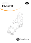
SERVICEMANUAL
IBIS X-SERIES
© 2008 Handicare
All rights reserved.
The information provided herein may not be reproduced and/or published in any form, by print, photo print, microfilm or any other means
whatsoever (electronically or mechanically) without the prior written authorisation of Handicare.
The information provided is based on general data concerning the constructions known at the time of the publication of this manual. Handicare
executes a policy of continuous improvement and reserves the right to changes and modifications.
The information provided is valid for the product in its standard version. Handicare cannot be held liable for possible damage resulting from
specifications of the product deviating from the standard configuration.
The available information has been prepared with all possible diligence, but Handicare cannot be held liable for possible errors in the
information or the consequences thereof.
Handicare accepts no liability for loss resulting from work executed by third parties.
Names, trade names, etc. used by Handicare may not, as per the legislation concerning the protection of trade names, be considered as being
available.
2008-01
2
Version 2008v2
1
2
3
Maintenance..........................................................................................................................................................7
1.1 Maintenance table ........................................................................................................................................7
1.2 Battery ..........................................................................................................................................................7
1.3 Replacement and repair activities for the Ibis XA ........................................................................................7
1.3.1
Rear wheels ...................................................................................................................................7
1.3.2
Replacing rear wheels ...................................................................................................................8
1.3.3
Repairing the tyre of the rear wheel...............................................................................................8
1.3.4
Replacing the tyre of the rear wheel ..............................................................................................8
1.3.5
Adjusting the pressure brake .........................................................................................................9
1.4 Replacement and repair activities for the Ibis XC and XC 16” and XC Power Support...............................9
1.4.1
Rear wheels ...................................................................................................................................9
1.4.2
Replacing the rear wheel of the Ibis XC ......................................................................................10
1.4.3
Replacing the rear wheel of Ibis XC 16” (option) .........................................................................10
1.4.4
Replacing the rear wheel of Ibis XC with Power Support (option)..............................................10
1.4.5
Repairing the tyre of the rear wheel.............................................................................................11
1.4.6
Replacing the tyre of the rear wheel ............................................................................................11
1.4.7
Adjusting the brake of an Ibis XC ................................................................................................12
1.4.8
Adjusting the pressure brake of the Ibis XC 16” (option) .............................................................12
1.4.9
Replacing the battery pack of the Ibis XC Power Support (option) .............................................12
1.4.10 Replacing the controller of the Ibis XC Power Support (option) ..................................................13
1.5 Replacement and repair activities for the Ibis XP ......................................................................................13
1.5.1
Replacing the driven wheel..........................................................................................................13
1.5.2
Repairing the tyre of the rear wheel.............................................................................................13
1.5.3
Replacing the tyre of the rear wheel ............................................................................................13
1.5.4
Replacing the motor.....................................................................................................................13
1.5.5
Replacing the batteries ................................................................................................................14
1.5.6
Replacing the Power Module .......................................................................................................14
1.5.7
Replacing the Controller ..............................................................................................................15
1.6 Replacing the swivel castor........................................................................................................................15
1.6.1
Replacing a wheel........................................................................................................................15
1.6.2
Replacing a fork ...........................................................................................................................16
1.7 Cleaning .....................................................................................................................................................16
Technical specification......................................................................................................................................17
2.1 Standard program for the Ibis XP with front-wheel drive ...........................................................................18
2.2 Standard program for the Ibis XP with rear-wheel drive ............................................................................20
2.3 Electrical wiring diagram of the XP ............................................................................................................22
2.4 Error codes of the XP fault table ................................................................................................................22
2.5 Fully discharged PowerSupport .................................................................................................................22
2.6 Authorised service and technical support ..................................................................................................23
Use of the parts lists ..........................................................................................................................................24
3.1 SEDEO .......................................................................................................................................................26
3.2 Ibis XA and Ibis XC ....................................................................................................................................40
3.3 Ibis XP (front-wheel and rear-wheel drive).................................................................................................48
3.4 Ibis XC 16” and Ibis XC Power Support .....................................................................................................62
3.5 Options, wiring and modules ......................................................................................................................69
Version 2008v2
3
Adjustment options
This manual
This manual contains the basic instructions for repairs and general maintenance of the Ibis manually operated
wheelchair.
Mechanics who do repairs on this wheelchair must be well trained and familiar with the repair methods and the
maintenance of the Ibis wheelchair.
Always make sure that the work is carried out safely, particularly with respect to procedures requiring the
wheelchair to be lifted up.
We advise that you contact our service department before doing repair work on a wheelchair that has been
involved in an accident.
The following specifications are important when ordering parts:
- Model
- Year of manufacture
- Colour
- Identification number
- Part number
- Name of the part concerned
This information is provided on the identification plate. See 'Identification of the product'.
Service and technical support
For information concerning specific settings, maintenance or repair works please contact your dealer. He is always
prepared to help you.
Ensure you have at hand:
- Model
- Year of manufacture
- Identification number
This information is provided on the identification plate. See 'Identification of the product'.
A
LAGE DIJK 10
5705 BZ HELMOND
THE NETHERLANDS
¨
Identification of the product
The identification plate contains the following data:
A. Model
B. Year of manufacture
C. Identification number
D. Use area indoors or outdoors
E. Maximum load in kg
B
C
CAT
2000 IDNR.: CT 00004
USAGE:
INDOOR/OUTDOOR
GEBRUIKSGEBIED:
BINNEN/BUITEN
GEBRAUCHSBEBIET:
INNERHALB/AUSSERHALB
MAX.LOAD/MAX.BELASTB./ZUL.GESAMTGEW.: 100 KG
TYPE/TYPE/TYP:
YEAR/JAAR/JAHR:
D
E
The location of the identification plate differs per model:
A. Ibis XA, Ibis XC, Ibis XC 16" and Ibis XC Power Support
B. Ibis XP with rear-wheel drive
C. Ibis XP with front-wheel drive
A
C
4
B
Version 2008v2
Adjustment options
Warranty stipulations concerning the wheelchair
In the following warranty and liability stipulations the terms and definitions as summed up hereafter must be
explained as follows:
•
Product:
The manually operated or electric wheelchair or electric scooter manufactured and delivered
by Handicare.
•
Customer:
The person who directly obtains a Product from Handicare or an authorised representative.
•
Dealer:
The person who delivers a Product obtained from Handicare to customers or third parties.
•
User:
The person who uses a Product manufactured by Handicare.
Irrespective of what is determined concerning warranty conditions applicable to the Product, in any case the
following applies with regard to the warranty:
1. Except insofar as described otherwise Handicare guarantees the Product for its suitability for the purpose for
which the Product is intended - all of these points as described in this manual - and for the quality of the
material of which the Product is made and the manner in which the Product is manufactured.
2. Repairs or replacement of parts of the Product that may be necessary as a result of faults that are based on
qualitatively faulty material or manufacturing errors will be executed free of charge, as long as such faults
occurred within one (1) year after the date of delivery of the Product to the Customer. The parts to be replaced
must be shipped postage-paid to Handicare. Installation or removal of these parts is for the Customer’s
account. Therefore, the following cases are not eligible for free repair or replacement as meant above:
- The repair or replacement that is necessary in connection with faults that arise after one (1) year after the
date of delivery of the Product to the Customer;
- The repair or replacement that is required in connection with faults due to improper or careless use of the
Product or that are based on the Product being used for another purpose than the one for which it is
intended, in which regard it applies that if the Customer is a Dealer, this Dealer will indemnify Handicare
against possible claims from Users or other third parties for faults based on an incorrect or careless use
of the Product;
- Parts that are subject to wear and the need for repair or replacement of the parts are the actual
consequence of normal wear. These can include, but are not limited to, tyres, shrouds, arm-pads, seating
etc.
3. Irrespective of that stipulated under 2, it applies as far as an electric Product is concerned that with regard to
the battery that forms part of the Product warranty is only given in case of faults or non-functioning of the
battery that are demonstrably the direct consequence of material or manufacturing errors. A fault or nonfunctioning of the battery as a result of normal wear is not covered by the warranty as meant in these warranty
stipulations. Similarly not covered by the warranty are faults or non-functioning that are the consequence of
improper or unprofessional use of the Product or the battery that is part of the Product, including the incorrect
charging of the battery and the failure to carry out timely and good maintenance, in which context it also
applies that if the Customer is a Dealer, this Dealer will indemnify Handicare against possible claims from
Users or other third parties that are based on the above mentioned improper or unprofessional use of the
Product or the battery that is part of the Product. Handicare does not guarantee batteries provided by dealers
or purchased by the customer.
4. The warranty conditions as mentioned in above stipulations in any case become null and void if:
- The guidelines of Handicare for the maintenance of the Product are not, or insufficiently, followed;
- A necessary repair or replacement of parts is based on neglect, damage or abuse of the Product or a use
of the Product for another purpose than the one for which it was intended;
- Parts of the Product are replaced by parts of another origin than those used by Handicare and/or parts of
the Product are replaced without the permission of Handicare.
5. The warranties as mentioned in stipulations 1 through 3 also become null and void if what is involved is reused by a new user within the warranty period and that such re-use necessitates adaptations to the wheelchair
and those adaptations are carried out without the instructions and/or at the order of Handicare.
6. To retain rights under the warranties delineated above, the Customer must, in case of damage or other
calamities, as rapidly as possible contact Handicare and inform them as fully as possible. The possibility of
taking recourse to the above-mentioned warranty conditions becomes null and void for the Customer in any
case after 20 workdays after the claim situation or the calamity arises that was the reason for the recourse to
the warranty.
7. The replacement of a part or the repair or the reconditioning of the Product within a current warranty period
does not extend the warranty period.
8. Handicare gives no warranty on repair to or reconditioning of the Product carried out other than under order of
and/or at the instructions of Handicare. If repairs and/or reconditioning are executed by or on behalf of a
Customer, the Customer indemnifies Handicare with respect to the claims of third parties that result, in the
broadest sense of the word, from such repairs or reconditioning.
Liability stipulations concerning the Product
Version 2008v2
5
Adjustment options
Irrespective of what is determined regarding liability in the general conditions applicable to the Product, with regard
to liability in any case the following applies:
1. Taking into consideration the following stipulations, Handicare only accepts liability for loss due to death or
physical injury that is the result of a defect in the Product for which Handicare is responsible and for damage
to another object that is the private property of the user of the Product, as long as said loss is the direct result
of a fault in the Product.
2. Handicare accepts no other or further liability than delineated under 1. In particular Handicare accepts no
liability for consequential damage, in any form whatsoever.
Wheelchairs and the environment
If the wheelchair needs to be replaced, it can usually be taken back by your dealer. If this is not
possible, please contact your local authorities for the possibilities of recycling or an environmentally
friendly way of disposing of the used materials.
For the production of the wheelchair various plastics and metals have been used.
Depending on the version, the wheelchair can contain electronic components that belong to
electronic waste, while the batteries belong to chemical waste.
6
Version 2008v2
Maintenance
1
Maintenance
1.1
Maintenance table
Everything that is used should be maintained. This is also true for your wheelchair.
Below, we have indicated what needs to be checked, how often this should be done, and by whom.
Time
Type Ibis
XA XC XP
X
X
X
X
X
X
X
X
X
X
X
X
X
X
X
X
X
X
Weekly
Monthly
Annually
(if necessary)
X
X
X
Description
•
•
•
•
•
•
•
Checking the tyre pressure
Cleaning of the frame.
Cleaning of the upholstery (if necessary)
General overhaul
Checking the bearings
Checking all fastenings and bolts: tighten if
necessary
Checking and cleaning of the brakes.
To be carried out by
Gebruiker
Dealer
X
X
X
X
X
X
-
X
It is recommended to have your wheelchair serviced by your dealer at least once a year, or, in case of intensive
use, once every six months.
1.2
Battery
For maintenance see the following documentation:
•
Regulations concerning the batteries.
•
User manual of the battery charger.
The wheelchair has 'dry' gel batteries. These dry batteries (dry-fit) are entirely sealed and maintenance free. The
connection diagram for the batteries is provided on a sticker inside the battery tray.
•
•
•
1.3
1.3.1
Make sure that the batteries are always well charged.
Do not use the wheelchair if the batteries are almost flat. This may damage the batteries and you
run the risk to come to an unintended standstill.
The use of 'wet' batteries is not permitted. If the batteries need to be replaced, use dry batteries
only.
Replacement and repair activities for the Ibis XA
Rear wheels
To ensure proper operation of the wheelchair, it is very important that the tyres are kept at the correct pressure.
Soft tyres yield less than optimal driving for the wheelchair. It also costs more energy to move the wheelchair
forward. Moreover, tyre wear when driving on soft tyres is unnecessarily great.
For the right tyre tension, see ‘Product specifications'.
Note when filling the tyres that the pressure never exceeds the maximum specified value provided
in the table 'product specification', or as indicated on the side of the tyre. When in doubt, contact
your dealer / supplier.
For the inspection of the tyres, see the 'maintenance table'.
Version 2008v2
7
Maintenance
1.3.2
Replacing rear wheels
C
The rear wheels should be removed as follows:
•
Remove locking nut (A) with a 17 mm box spanner.
•
Remove the complete rear wheel (B) from axle (C).
•
Remove the tyres, see ‘Repairing the tyre of the rear
wheel’ or ‘Replacing the tyre of the rear wheel'.
Fit the new wheel in the reverse order.
Attention:
The locknut may not be used again – use a
new one when replacing.
Always check the proper locking of the rear
wheels. Try to pull the wheel out of the frame
in axial direction. If the wheel comes out, it is
not properly secured. In that case, you should
repeat the above actions.
1.3.3
B
A
Repairing the tyre of the rear wheel
Repair a flat tyre as follows:
•
Remove the rear wheel to be repaired from the wheelchair. See ’Removing the rear wheels’.
•
Twist off the valve to let the air out of the tyre completely.
•
Using tyre levers pull one side of the tyre across the edge of the rim.
•
Remove the inner tube from the rim.
•
Repair the inner tube or replace it (this is done in the same way as a bicycle tyre).
Reassemble the tyre (with repaired or new inner tube) as follows:
Put the valve through the opening in the rim.
Carefully place the tyre around the rim.
Add a little air to the inner tube in order to position it comfortably around the rim.
Pull the tyre onto the rim as far as possible.
Allow all air to escape from the inner tube.
Now pull the tyre completely onto the centre of the rim as tightly as possible.
The rim has a room into which the tyre must be pulled, in order to create sufficient space to be able to pull the
complete tyre onto the rim by hand.
•
Pull the tyre completely onto the rim.
•
•
•
•
•
•
Do not use tyre levers to do this, because the inner tube is easily damaged by these. Moreover, the
tyre is easily assembled without tyre levers.
•
Make sure that the tyre is properly fitted onto the rim.
The inner tube may not protrude from under the tyre anywhere!
•
•
Pump up the tyre.
Mount the wheel back onto the wheelchair. See ’Removing the rear wheels’.
1.3.4
Replacing the tyre of the rear wheel
The tyre should be replaced as follows:
Remove the rear wheel to be repaired from the wheelchair. See ’Removing the rear wheels’.
Twist off the valve to let the air out of the tyre completely.
Using tyre levers, pull one side of the tyre across the edge of the rim.
Remove the inner tube from the rim.
Remove the other part of the tyre from the rim.
•
•
•
•
•
Now install a new tyre as follows:
•
Place one side of the new tyre across the rim.
8
Version 2008v2
Maintenance
•
•
•
•
•
•
•
Put the valve through the opening in the rim.
Carefully place the tyre around the rim.
Add a little air to the inner tube in order to position it comfortably around the rim.
Pull the tyre onto the rim as far as possible.
Allow all air to escape from the inner tube.
Now pull the tyre completely onto the centre of the rim as tightly as possible.
The rim has a room into which the tyre must be pulled, in order to create sufficient space to be able to pull the
complete tyre onto the rim by hand.
Pull the tyre completely onto the rim.
Do not use tyre levers to do this, because the inner tube is easily damaged by these. Moreover, the
tyre is easily assembled without tyre levers.
•
Make sure that the tyre is properly fitted onto the rim.
The inner tube may not protrude from under the tyre anywhere!
•
•
Pump up the tyre.
Mount the wheel back onto the wheelchair. See ’Removing the rear wheels’.
1.3.5
Adjusting the pressure brake
The wheelchair is fitted with pressure brakes on the rear
wheels, which the user can operate by hand.
B
A
Proper functioning of the brakes is essential. That’s why the
brakes have to be:
•
properly adjusted
•
replaced in time.
Adjust the brakes as follows:
•
Loosen screw (A) one turn using a 5 mm Allen key.
•
Slide brake unit (B) along the tube for the adjustment.
- away from the wheel: brake looser.
- towards the wheel: brake tighter.
•
Tighten the screw in the set position.
1.4
1.4.1
Replacement and repair activities for the Ibis XC and XC 16” and XC Power Support
Rear wheels
To ensure proper operation of the wheelchair, it is very important that the tyres are kept at the correct pressure.
Soft tyres yield less than optimal driving for the wheelchair. It also costs more energy to move the wheelchair
forward. Moreover, tyre wear when driving on soft tyres is unnecessarily great.
For the right tyre tension, see ‘Product specifications'.
Note when filling the tyres that the pressure never exceeds the maximum specified value provided
in the table 'product specification', or as indicated on the side of the tyre. When in doubt, contact
your dealer / supplier.
For the inspection of the tyres, see the 'maintenance table'.
Version 2008v2
9
Maintenance
1.4.2
Replacing the rear wheel of the Ibis XC
When replacing a rear wheel, the wheel may not be braked.
Replace the rear wheel as follows:
•
Support the wheelchair in such a way that the wheel is
elevated.
•
Remove locking nut (A) with a 12 mm box spanner.
•
Pull wheel (B) off the axle (C).
•
Remove the tyres; see ‘Repairing the tyre of the drive
wheel’ or ‘Replacing the tyre of the drive wheel’.
Fit the new wheel in the reverse order.
C
B
1.4.3
A
Replacing the rear wheel of Ibis XC 16” (option)
When replacing a rear wheel, the wheel may not be braked.
Replace the rear wheel as follows:
•
Support the wheelchair in such a way that the wheel is
elevated.
•
Remove locking nut (A) with a 17 mm box spanner.
•
Pull wheel (B) off the axle (C).
•
Remove the tyres; see ‘Repairing the tyre of the drive
wheel’ or ‘Replacing the tyre of the drive wheel’.
Fit the new wheel in the reverse order.
C
B
1.4.4
Replacing the rear wheel of Ibis XC with
Power Support (option)
A
A
B
When replacing a rear wheel, the wheel may not be braked.
Replace the rear wheel as follows:
•
Support the wheelchair in such a way that the wheel is
elevated.
•
Remove nut (A) with a 19 mm open-ended spanner.
•
Remove wheel (B).
•
Remove the tyres; see ‘Repairing the tyre of the drive
wheel’ or ‘Replacing the tyre of the drive wheel’.
Fit the new wheel in the reverse order.
10
Version 2008v2
Maintenance
1.4.5
Repairing the tyre of the rear wheel
When repairing the inner tube of a rear wheel, the wheel should be braked, so that it does not rotate at the same
time.
Repair a flat tyre as follows:
•
Support the wheelchair in such a way that the wheel is elevated.
•
Pull out the valve to completely deflate the tyre.
•
Using tyre levers pull the front of the tyre across the edge of the rim.
•
Carefully pull the inner tube across the edge of the rim.
•
Push the valve from the opening in the rim.
•
Pull the inner tube from the tyre for repair or replacement.
•
Repair the inner tube or replace it.
Now, the repaired or new inner tube should be placed as follows:
•
Put the valve of the inner tube through the opening in the rim.
•
Press the inner tube into the tyre.
•
Place the tyre around the rim.
•
Use tyre levers to place the tyre around the rim: be careful not to damage the inner tube with the tyre levers.
The inner tube must not become jammed between the rim and the tyre.
•
•
Pump up the inner tube, see 'technical data'.
Remove the support from under the wheelchair.
The wheelchair is ready for use.
1.4.6
Replacing the tyre of the rear wheel
When replacing a tyre of a rear wheel, the wheel should be braked, so that it does not rotate at the same time.
Replace a tyre as follows:
•
Support the wheelchair in such a way that the wheel is elevated.
•
Pull out the valve to completely deflate the tyre.
•
Using tyre levers pull the front of the tyre across the edge of the rim.
•
Carefully pull the inner tube across the edge of the rim.
•
Push the valve from the opening in the rim.
•
Pull the inner tube from the tyre.
•
The whole tyre can now be removed.
Now the tyres (with repaired or new inner tube) should be assembled as follows:
•
Place one side of the tyre around the rim.
•
Put the valve of the inner tube through the opening in the rim and press the inner tube into the tyre.
•
Place the tyre around the rim.
•
Use tyre levers to place the tyre around the rim: be careful not to damage the inner tube with the tyre levers.
The inner tube must not become jammed between the rim and the tyre.
•
•
Pump up the inner tube, see 'technical data'.
Remove the support from under the wheelchair.
The wheelchair is ready for use.
Version 2008v2
11
Maintenance
1.4.7
Adjusting the brake of an Ibis XC
The wheelchair is equipped with drum brakes on the rear
wheels, which can be either operated by hand by the user, or
with the foot by the person pushing the wheelchair.
Proper functioning of the brakes is essential. That’s why the
brakes have to be:
•
properly adjusted
•
replaced in time.
A
B
Adjust the brakes as follows:
•
Loosen nut (A).
•
Remove nut (B) with a 10 mm open-ended spanner.
- Clockwise: brake tighter.
- Anti-clockwise: brake looser.
1.4.8
Adjusting the pressure brake of the Ibis XC 16”
(option)
A
B
The wheelchair is equipped with drum brakes on the rear
wheels, which can be either operated by hand by the user, or
with the foot by the person pushing the wheelchair.
Proper functioning of the brakes is essential. That’s why the
brakes have to be:
•
Properly adjusted
•
Replaced in time.
Adjust the brakes as follows:
•
Loosen screw (A) one turn using a 5 mm Allen key.
•
Slide brake unit (B) along the tube for the adjustment.
- Away from the wheel: brake looser.
- Towards the wheel: brake tighter.
•
Tighten the screw in the set position.
1.4.9
Replacing the battery pack of the Ibis XC Power
Support (option)
Replace the battery pack as follows:
•
Disconnect cables (A) to the motor and the controller.
•
Loosen the four screws (A) using a 4 mm Allen key.
•
Remove battery pack (C).
A
C
Fit the battery pack in the reverse order.
B
12
Version 2008v2
Maintenance
1.4.10 Replacing the controller of the Ibis XC Power
Support (option)
Replace the controller as follows:
•
Cut the Ty-Raps that hold the cable.
•
Loosen three cross-head screws (A).
Remove the controller.
B
Fit a new controller in the reverse order.
A
1.5
Replacement and repair activities for the Ibis XP
1.5.1
Replacing the driven wheel
Replace a driven wheel as follows:
•
Support the wheelchair in such a way that the wheel is
elevated.
•
Loosen cross-head screw (A).
•
Remove protective cover (B).
•
Loosen hexagonal bolt (C) with a 17 mm box spanner.
•
Pull wheel (D) off the axle (E).
E
Fit a new wheel in the reverse order.
1.5.2
Repairing the tyre of the rear wheel
See below: ‘Replacement and repair activities for the Ibis XC’.
1.5.3
Replacing the tyre of the rear wheel
See below: ‘Replacement and repair activities for the Ibis XC’.
1.5.4
Replacing the motor
Replace the motor as follows:
Step 1:
•
Loosen the star knobs (A).
•
Remove battery cover (B).
•
Remove fuses (C).
•
D
C
B
A
A
D
B
Step 2:
Disconnect the motor cable from power module (D).
C
A
Version 2008v2
13
Maintenance
Step 3:
•
Remove the wheel; see 'Replacing drive wheel'.
•
Loosen three Allen bolts (A) and nut (B) with a 5 mm Allen
key and remove motor (C). Use a 10 mm open-ended
spanner for the nut.
Fit a new motor in the reverse order.
B
C
1.5.5
A
Replacing the batteries
A
Replace the batteries as follows:
Step 1:
•
See 1.5.4 (step 1).
Step 2:
•
Release battery strap (A).
•
Disconnect the cables from batteries (B) by unscrewing the
bolts from the battery terminals (C) with a 10 mm openended or ring spanner.
•
Remove the batteries from the wheelchair.
C
Fit new batteries in the reverse order.
B
1.5.6
Replacing the Power Module
Replace the Power Module as follows:
Step 1:
•
See 1.5.4 (step 1).
Step 2:
•
Unscrew both screws (A) with a 3 mm Allen key and
remove battery pack (B).
B
A
Fit a new Power Module in the reverse order.
14
Version 2008v2
Maintenance
1.5.7
Replacing the Controller
Replace the controller as follows:
Step 1:
•
See 1.5.4 (step 1).
Step 2:
•
Cut the Ty-Raps that hold the cable to the frame and to
other cabling.
•
Loosen the four screws (A).
•
Remove the controller (B).
B
Fit a new controller in the reverse order.
A
1.6
Replacing the swivel castor
For the proper functioning of the wheelchair, it is very
important that the wheels are kept in order.
The following parts can be replaced:
•
Wheel (A), see 'Replacing a wheel'.
•
Fork (B), see 'Replacing a fork'.
B
A
1.6.1
Replacing a wheel
Replace a wheel as follows:
•
Loosen the Allen bolt (A) with an Allen key with a key width
of 5 mm.
•
Slide wheel (B) out of the fork (C).
C
Fit a new wheel in the reverse order.
A
B
Version 2008v2
15
Maintenance
1.6.2
Replacing a fork
Replace the fork as follows:
•
Remove the wheel from the fork; see 'Replacing a wheel'.
•
Remove screw (A) with a Phillips screwdriver.
•
Remove cap (B).
•
Loosen bolt (C) using a 19 mm box spanner and prevent
nut (D) from moving with a 19 mm ring spanner.
•
Take fork (E) out of the frame.
Take care not to lose the washers (F).
C
F
B
F
Mount the fork in the reverse order.
Attention:
The locknut may not be used again – use a
new one when replacing.
A
E
D
1.7
Cleaning
Removing dry dirt
Upholstery, metal parts and frame parts can usually be cleaned easily with a dry soft cloth.
Removing mud and/or other wet dirt
Parts that are soiled with wet dirt can best be cleaned by first wiping the dirty parts with a wet sponge and then
wiping them dry with a dry soft cloth.
Upholstery
Cleaning with a damp cloth and household soap. After removing the dirt the cleaned parts should be wiped dry with
a soft dry cloth.
-
16
Never use abrasive or aggressive cleansers. They may damage the wheelchair.
Also do not use organic solvents such as thinner, dry-cleaning naphtha, or white spirit.
Upholstery: do not dry clean, iron or spin dry.
Version 2008v2
Technical specifications
2
Technical specification
Description
Description
Model
Max. user weight
Total length
Total width Ibis XC
Total width Ibis XA
Total weight
Total weight of the heaviest
part Ibis XC
Total weight of the heaviest
part Ibis XA
Static stability downward
Static stability upward
Static stability sideways
Seat tilt adjustment
Seat angle
Effective seat depth
Effective seat width Ibis XC
Effective seat width Ibis XA
Seat height front
Backrest angle
Backrest height
Lower leg length
Armrest height
Front armrest to backrest
Minimum turning radius
Ground clearance
Push bracket height
Ibis XC / XA
160 kg
1040 mm
625 mm
660-700-740
mm
40 kg
26 kg
28 kg
15°
15°
15°
30°
0 - 6°
440 - 520 mm
380 - 555 mm
380 - 555 mm
390 - 540 mm
89 - 118°
520 - 570 mm
390 - 500 mm
180 - 280 mm
370 - 450 mm
810 mm
70 mm
830 - 1200 mm
Wheels
Diameter front wheel
Diameter rear wheels Ibis XC
7”
12” / 16”
Diameter rear wheels Ibis XA
20” / 22” / 24”
Tyre pressure rear wheels
12’’: 2.5 bar
20’’ / 22’’ / 24’’:
7.5 bar
Model
Max. user weight
Total length
Total width
Total weight excl. batteries
Static stability downward
Static stability upwards
Static stability sideways
Range (ISO 7176) 33 Ah/c5
batteries
Range (ISO 7176) 40 Ah/c5
batteries
Dynamic stability on slopes
FWD
Dynamic stability on slopes
RWD
Climbing capacity for
obstacles FWD
Climbing capacity for
obstacles RWD
Climbing capacity for
obstacles RWD with kerb
climber
Maximum speed
Seat tilt
Seat angle
Effective seat depth
Effective seat width
Seat height front
Backrest angle
Backrest height
Lower leg length
Armrest height
Front armrest to backrest
Minimum turning radius
RWD
Minimum turning radius
FWD
Ground clearance
Ibis XP
160 kg
1040 mm
595 mm
60 kg
15°
15°
15°
25 km
31 km
6°
14°
70 mm
50 mm
100 mm
6 km/h
15°
0 - 6°
440 – 520 mm
380 – 555 mm
435 – 540 mm
89 - 120°
520 – 570mm
390 – 500 mm
180 – 280 mm
370 – 450 mm
790 mm
600 mm
60 mm
Wheels
Diameter castor wheel
Diameter drive wheel
Tyre pressure castor wheel
8"
12,5”
2,5 Bar
Tyre pressure drive wheel
2,7 Bar
Batteries
Version 2008v2
Maximum dimensions
batteries FWD (WxDxH)
Maximum dimensions
batteries RWD (WxDxH)
Maximum battery capacity
Maximum permissible
charging voltage
Maximum charging current
278x200x180
Connector type
A DIN 72311
278x358x180
30 / 40 Ah
24 V
10 A
17
Technical specifications
2.1
Standard program for the Ibis XP with front-wheel drive
General settings
FWD
Lowest Forward Speed (%)
Lowest Turning Speed (%)
Sleep Timer (Min)
Wakeup Style
Beep on Key press
Speed Button Sensitivity
Joystick Throw
Joystick Switch Threshold (%)
Lock Enable
Field Programmability
Active Drive Program
Emergency Deceleration (%)
Speedo Display
Indicator Auto-cancel
Drive Programs
Drive Program Name
Maximum Forward Speed (%)
10
10
0
Buttons
Yes
5
Normal
40
No
Full
Program 3
60
Maximum Speed
15 sec
Program 1
RWD
95
Program 2
Med Chair
95
Program 3
FWD
95
Forward Acceleration (%)
Forward Deceleration (%)
Maximum Reverse Speed (%)
Reverse Acceleration (%)
Reverse Deceleration (%)
Maximum Turning Speed (%)
Turning Acceleration (%)
Turning Deceleration (%)
Tremor Damping (%)
Load Compensation (mOhm)
Maximum Load Compensation (mOhm)
Active Stability Profile
Traction (%)
Attendant Drive Program
Maximum Forward Speed (%)
Forward Acceleration (%)
Forward Deceleration (%)
Maximum Reverse Speed (%)
Reverse Acceleration (%)
Reverse Deceleration (%)
Maximum Turning Speed (%)
Turning Acceleration (%)
Turning Deceleration (%)
Tremor Damping (%)
Joystick Swap Forward/Reverse
Joystick Swap Left/Right
Stability Profiles 1 to 4
Stability Profile Name
25
55
40
30
55
30
20
60
40
80
400
Profile 1
0
25
55
40
30
55
30
20
60
40
80
400
Profile 2
0
25
45
40
30
55
30
10
40
40
80
400
Profile 4
20
100
40
60
70
35
70
50
40
60
40
No
No
Profile 1
RWD
Profile 2
Lo Chair
Profile 3
Med Chair
Profile 4
FWD
Maximum Speed in turn (%)
Speed Acceleration Scalar (%)
Turning Acceleration Scalar (%)
Turning at Maximum Speed (%)
Turning Acceleration at Maximum Speed (%)
Traction at Maximum Speed pot (%)
FWD/RWD Swivel
100
0
0
100
100
0
No
15
0
0
100
100
0
No
10
0
0
100
100
0
No
5
0
0
40
100
15
No
18
Version 2008v2
Technical specifications
Stability Profiles 5 to 8
Stability Profile Name
Maximum Speed in turn (%)
Speed Acceleration Scalar (%)
Turning Acceleration Scalar (%)
Turning at Maximum Speed (%)
Turning Acceleration at Maximum Speed (%)
Traction at Maximum Speed pot (%)
FWD/RWD Swivel
Motor/Brake
Parking brake Type
Software Current Limit (A)
Boost Current (A)
Boost Time (s)
Stall Timeout (s)
Spring Compensation
Motor swap
Left Motor Invert
Right Motor Invert
Enable Soft Start
Maximum Motor Volts (V)
Motor Short circuit Test
DCI Options
DCI Type
DCI Operation
DCI Speed Limit 1 (%)
DCI Speed Limit 2 (%)
DCI Speed Limit 3 (%)
OBC Inhibit Operation
Seat Options
Seat Control Type
Seat 1 Current (A)
Seat 1 Speed (%)
Seat 1 Boost Level (%)
Seat 1 Boost Time (s)
Seat 2 Current (A)
Seat 2 Speed (%)
Seat 2 Boost Level (%)
Seat 2 Boost Time (s)
Actuator Stall Time (s)
Actuator While Charging
Miscellaneous Settings
o
Thermal Rollback Start ( C)
o
Thermal Rollback End ( C)
o
FET Thermal Rollback Start ( C)
o
FET Thermal Rollback End ( C)
Version 2008v2
Profile 5
NoCT Swivel
100
0
0
100
100
0
No
Profile 6
LoCT Swivel
15
0
0
100
100
0
No
Profile 7
MedCT Swivel
10
0
0
100
100
0
No
Profile 8
HiCT Swivel
5
0
0
100
100
0
No
Dual
40
15.0
10
15
Off
Yes
Yes
Yes
Yes
26
Yes
Swivel
Normally
50
50
50
Off
Switched
0.0
100
100
2.0
0.0
100
100
2.0
0.5
Yes
60
75
80
90
19
Technical specifications
2.2
Standard program for the Ibis XP with rear-wheel drive
General settings
RWD
Lowest Forward Speed (%)
Lowest Turning Speed (%)
Sleep Timer (Min)
Wakeup Style
Beep on Key press
Speed Button Sensitivity
Joystick Throw
Joystick Switch Threshold (%)
Lock Enable
Field Programmability
Active Drive Program
Emergency Deceleration (%)
Speedo Display
Indicator Auto-cancel
Drive Programs
Drive Program Name
Maximum Forward Speed (%)
Forward Acceleration (%)
Forward Deceleration (%)
Maximum Reverse Speed (%)
Reverse Acceleration (%)
Reverse Deceleration (%)
Maximum Turning Speed (%)
Turning Acceleration (%)
Turning Deceleration (%)
Tremor Damping (%)
Load Compensation (mOhm)
Maximum Load Compensation (mOhm)
Active Stability Profile
Traction (%)
Attendant Drive Program
Maximum Forward Speed (%)
Forward Acceleration (%)
Forward Deceleration (%)
Maximum Reverse Speed (%)
Reverse Acceleration (%)
Reverse Deceleration (%)
Maximum Turning Speed (%)
Turning Acceleration (%)
Turning Deceleration (%)
Tremor Damping (%)
Joystick Swap Forward/Reverse
Joystick Swap Left/Right
Stability Profiles 1 to 4
Stability Profile Name
Maximum Speed in turn (%)
Speed Acceleration Scalar (%)
Turning Acceleration Scalar (%)
Turning at Maximum Speed (%)
Turning Acceleration at Maximum Speed (%)
Traction at Maximum Speed pot (%)
FWD/RWD Swivel
10
10
0
Joystick
Yes
5
Normal
40
No
Full
Program 1
60
Maximum Speed
15 sec
Program 1
RWD
95
25
55
40
30
55
30
20
60
40
80
400
Profile 1
0
20
100
40
60
50
35
70
50
40
60
40
No
No
Profile 1
RWD
100
0
0
100
100
0
No
Program 2
Med Chair
95
25
55
40
30
55
30
20
60
40
80
400
Profile 3
0
Profile 2
Lo Chair
15
0
0
100
100
0
No
Program 3
FWD
95
25
45
40
30
55
20
10
40
40
80
400
Profile 3
50
Profile 3
Med Chair
5
0
0
40
100
0
No
Profile 4
FWD
5
0
0
40
100
0
No
Version 2008v2
Technical specifications
Stability Profiles 5 to 8
Stability Profile Name
Maximum Speed in turn (%)
Speed Acceleration Scalar (%)
Turning Acceleration Scalar (%)
Turning at Maximum Speed (%)
Turning Acceleration at Maximum Speed (%)
Traction at Maximum Speed pot (%)
FWD/RWD Swivel
Motor/Brake
Parking brake Type
Software Current Limit (A)
Boost Current (A)
Boost Time (s)
Stall Timeout (s)
Spring Compensation
Motor swap
Left Motor Invert
Right Motor Invert
Enable Soft Start
Maximum Motor Volts (V)
Motor Short circuit Test
DCI Options
DCI Type
DCI Operation
DCI Speed Limit 1 (%)
DCI Speed Limit 2 (%)
DCI Speed Limit 3 (%)
OBC Inhibit Operation
Seat Options
Seat Control Type
Seat 1 Current (A)
Seat 1 Speed (%)
Seat 1 Boost Level (%)
Seat 1 Boost Time (s)
Seat 2 Current (A)
Seat 2 Speed (%)
Seat 2 Boost Level (%)
Seat 2 Boost Time (s)
Actuator Stall Time (s)
Actuator While Charging
Miscellaneous Settings
o
Thermal Rollback Start ( C)
o
Thermal Rollback End ( C)
o
FET Thermal Rollback Start ( C)
o
FET Thermal Rollback End ( C)
Version 2008v2
Profile 5
NoCT Swivel
100
0
0
100
100
0
No
Profile 6
LoCT Swivel
15
0
0
100
100
0
No
Profile 7
MedCT Swivel
10
0
0
100
100
0
No
Profile 8
HiCT Swivel
5
0
0
100
100
0
No
Dual
40
15.0
10
15
Off
Yes
No
No
Yes
26
Yes
Swivel
Normally
50
50
50
Off
Switched
0.0
100
100
2.0
0.0
100
100
2.0
0.5
Yes
60
75
80
90
21
Technical specifications
2.3
Electrical wiring diagram of the XP
2.4
Error codes of the XP fault table
Check the malfunction/signal with the aid of the following list.
Flash
1
2
3
4
5
6
7
8
9
10
11
2.5
Description
User Fault
Battery Fault
Left Motor Fault
Right Motor Fault
Left Parking Brake Fault
Right Parking Brake Fault
SHARK Control Unit Fault
SHARK Power Module Fault
SHARK Communications Fault
Unknown Fault
Incompatible Control Unit
Possible stall timeout or user error
Check the batteries & cabling
Check the left motor connections & cabling
Check the right motor connections & cabling
Check the left parking brake connections & cabling
Check the right parking brake connections & cabling
Check the SHARK Communications Bus
Check the SHARK connections & wiring
Check the SHARK connections & wiring
Check all connections & wiring
Wrong type of Control Unit Connected
Fully discharged PowerSupport
Normally the PowerSupport starts charging when the charger is connected. If this does not happen, the
PowerSupport may be fully discharged. To activate the PowerSupport external voltage is needed. The motor can
serve as a source for this. Connect the charger and turn the wheel calmly round. Increase speed slowly until the
led lights flashes on the control unit. Because the charger is already connected, the PowerSupport will start
charging. Please note: the PowerSupport must be fully charged.
Please feel free to contact one of our service engineers if you have any further questions.
22
Version 2008v2
Technical specifications
2.6
Authorised service and technical support
If you have any problems or questions concerning this product, please contact your dealer.
Ask us for information about your nearest dealer.
Manufacturer:
Handicare
Supplier’s stamp
Version 2008v2
23
Parts lists
3
Use of the parts lists
This document is meant as a reference book to be used to order parts for the wheelchair that is shown on the front
cover.
How to order:
When ordering parts, please specify:
•
Serial number (see the identification plate)
•
Group (to which the relevant part belongs)
•
Article number
•
Number of parts required
•
Description (in the relevant language)
•
Dimensions (if applicable)
Remark:
•
If a part does not have a position number, it means that the part concerned cannot be purchased separately. The
part concerned is part of the assembly shown. This assembly must be ordered as one piece. It has to be replaced in
its entirety.
•
Boxed position numbers refer to the relevant drawing.
Order address:
Please mail or fax your orders to your supplier.
Service technicians:
Repairs may only be carried out by trained and authorised service technicians.
During the execution of their work they are at all times fully responsible for the fulfilment of locally applicable safety
guidelines and standards.
Temporary employees and persons in training may only carry out repair and replacement work under the
supervision of an authorised service technician.
24
Version 2008v2
Parts lists
•
Overview
001 t/m 010
011 t/m 017
Drawing
001-010
011-017
018-028
029-036
037-043
Version 2008v2
018 t/m 028
029 t/m 036
Description
Sedeo
Ibis XA/XC
Ibis XP
Ibis XC 16” and Ibis XC Power Support
Options, wiring and modules
037 t/m 043
Page
26-39
40-47
48-61
62-68
69-76
25
Parts lists
3.1
SEDEO
008
006
009
007
002
003
003
008
001
005
004
010
Drawing
001
002
003
004
005
006
007
008
009
010
26
Description
Sedeo seating frame
Upper part
Armrest XA XC XP
Central legrest XA/XC
Central legrest XP
Standard leg rest
Comfort mechanical leg rest
Seat / backrest / calf plate
Head rest
Gas spring backrest adjustment
Page
27
28
29
30
31
32
33
35
38
39
Version 2008v2
Parts lists
001: Sedeo seating frame
•
1
2
5
6
5
3
16
4
15
2
2
4
26
25
24
23
22
7
3
2
18 17
14
27
21
20
19
Pos
1
2
3
4
5
6
7
8
9
10
11
12
13
14
15
16
17
18
19
20
21
22
23
24
25
26
27
Article number
02030.4123
00000.9009
00001.0204
00000.1401
00000.3728
02030.3423
02030.4223
1008035
00000.2103
00000.1502
00000.2003
00000.4135
1003247
9001146
9001181
9001180
9001182
00000.6801
1003247
1003247
00000.4113
00000.2103
9001142
9001145
9000951
00000.3519
9000673
02030.4023
00000.4002
Version 2008v2
Units
1
4
2
2
2
1
1
1
3
2
2
1
1
1
1
1
1
2
2
2
2
2
2
2
1
4
2
2
1
9 10 11
18
17
16
12 11 10 13
8
Description
Back part 2 Sedeo short back arm
Insert cap round 15 black
Washer
Shaft lock washer 15mm
Button head M8X12
Back tube
Back part 2 Sedeo long back arm
Backrest adjustment assy, Ibis X-series
Washer flat 3XD M8
Hex Nut M8
Washer flat M8
Hex. Bolt M8x25
Label back rest angle (sticker sheet)
Armrest holder left, Ibis X-series
Ext. armrest holder left, Ibis X-series
Arm holder right, Ibis X-series
Ext. armrest holder right, Ibis X-series
Wing bolt M8X20; L=40
Label width adj. arm rest (standard), Ibis X (sticker sheet)
Label width adj. arm rest (wide), Ibis X-ser. (sticker sheet)
Hex bolt M8X35
Washer flat 3xD M8
Armrest clamp plate, Ibis X-series
Nut plate weld assy, Ibis X-series
Sedeo seating frame, Ibis X-series
Adjusting screw M8X10
Clamping plate, Sedeo
Back part 1 Sedeo
Socket screw M8X16
Price p/p 2008
€ 33,00
€ 0,20
€ 0,60
€ 2,20
€ 0,70
€ 21,00
€ 35,00
€ 38,00
€ 0,20
€ 0,20
€ 0,20
€ 0,20
€ 5,50
€ 50,00
€ 54,00
€ 50,00
€ 54,00
€ 1,80
€ 5,50
€ 5,50
€ 0,30
€ 0,20
€ 13,00
€ 8,40
€ 179,00
€ 0,20
€ 2,70
€ 31,00
€ 0,30
27
Parts lists
•
002: Upper part
1
2
5
3 4
6
1
9
7
7
11
8
12
13
10
12
Pos
1
2
3
4
5
6
7
8
9
10
11
12
13
28
Article number
00000.4801
1007008
1008057
1007684
00001.1400
02030.0111
00000.6801
1001834
9001374
9001155
9001156
1003247
00000.3501
Units
2
1
1
1
1
1
2
1
1
1
1
2
4
Description
Handle black
Handle mechanical seat adj.
Mechanical cable
Adjusting nipple
Label tilt adjustment
Handlebars
Wing bolt M8X20; L=40
Back frame
Push frame small XP
Leg rest holder left, Ibis X-series
Leg rest holder right, Ibis X-series
Label leg rest width, Ibis X-series (sticker sheet)
Adjusting screw M8X10
Price p/p 2008
€ 5,50
€ 12,00
€ 12,00
€ 1,90
€ 0,50
€ 88,00
€ 1,80
€ 85,00
€ 59,00
€ 41,00
€ 41,00
€ 5,50
€ 0,70
Version 2008v2
Parts lists
003: Armrest XA XC XP
•
9
1
10
2
3
11
4
12
5
13
15
7
6
16
8
14
17
XA/XP
XC
Pos
1
2
3
4
5
6
7
8
9
10
11
12
13
14
15
16
17
Article number
221.00111.505
00000.3206
02040.0311
00000.3541
02040.0223
224.00241.505
02040.0782
00000.3207
1008038
1008037
1003060
9000956
02040.0223
00000.3541
1008039
00000.3206
02040.0782
00000.1700
Version 2008v2
Units
2
4
2
2
2
2
2
4
1
1
4
2
2
2
2
4
2
4
Description
Armrest 40 cm
Screw M5X16
Upper part long
Adjusting screw M8X10
Centre piece
Side cushion
Bracket
Screw M5X20
PU armrest soft, left, XA/XP
PU armrest soft, right, XA/XP
Thread cutting screw M5x16
Armrest holder, Ibis X-series
Centre piece
Adjusting screw M8X10
Side plate standard, Ibis XA/XP
ScrewM5X16
Bracket
Locknut M5
Price p/p 2008
€ 50,00
€ 0,30
€ 31,00
€ 0,70
€ 27,00
€ 47,00
€ 8,40
€ 0,30
€ 48,00
€ 48,00
€ 0,30
€ 28,00
€ 27,00
€ 0,70
€ 37,00
€ 0,30
€ 8,40
€ 0,20
29
Parts lists
•
004: Central legrest XA/XC
10
11
12
6
5
4
1
3
9
7
2
8
Pos
1
2
3
4
5
6
7
8
9
10
11
12
30
Article number
1001087
9001218
1002808
1001086
00000.6410
00000.1700
00000.3616
01050.2480
00000.3614
220.00201.505
00000.2002
00000.4016
Units
1
1
1
1
1
2
2
1
2
1
2
2
Description
Central legrest
Cable
Gas spring bloc-o-lift 400N+unlock+nut
Metalparts central legrest
Handle
Lock nut M5
Screw M5x12
Footplate
Screw M6x20
Calf pad trapezium
Washer flat M6 D125A/VZ
Cyl cap screw M6x25
Price p/p 2008
€ 230,00
€ 6,80
€ 100,00
€ 190,00
€ 9,50
€ 0,20
€ 0,20
€ 43,00
€ 0,30
€ 72,00
€ 0,20
€ 0,20
Version 2008v2
Parts lists
•
005: Central legrest XP
2
3
4
14
13
1
5
6
12
6
10
11
7
8
10
9
Pos
1
2
3
4
5
6
7
8
9
10
11
12
13
14
Article number
140.00061.000
9001719
00001.1324
00000.3706
20050.1311
00000.5002
00000.4100
01050.2011
00000.3614
00000.9002
01050.1411
00000.1702
20050.2480
00000.3614
Version 2008v2
Units
1
1
1
1
1
2
1
1
2
2
1
1
1
2
Description
Central leg rest XP
Upper part hinge
Label tilting hazard
Button head M8X25
Lower tube
Bearing bush nylon 8x11x13
Hex bolt M8X150
Strip
Screw M6X20
Insert cap round 22 black
U-pipe
Lock nut M8
Footplate
Screw M6X20
Price p/p 2008
€ 222,00
€ 92,00
€ 1,30
€ 0,40
€ 50,00
€ 0,70
€ 1,10
€ 7,60
€ 0,30
€ 0,20
€ 75,00
€ 0,30
€ 39,00
€ 0,30
31
Parts lists
006: Standard legrest
•
8
9
10
7
3
2
1
4
5
6
Pos
Article number
Units
-
1
-
1
1002515
1002514
01500.1112
01500.2212
1
1
2
2
-
1
-
1
01263.9000
1004189
1004188
00000.2601
00000.3725
01500.2110
1
2
2
4
4
4
1
2
3
4
5
6
7
8
9
10
32
Description
Standard leg rest left
See page 34.
Standard leg rest right
See page 34.
Standard leg rest upper part left
Standard leg rest upper part right
Legrest release lever
Legrest release spring
Footplate left
See page 34.
Footplate right
See page 34.
Calf strap
Calf plate hinge standard
Calf plate hinge small
Toothed spring washer M6
Button head M6X10
Leg rest clamping strip short
Price p/p 2008
€ 69,00
€ 69,00
€ 9,50
€ 0,70
€ 14,00
€ 98,00
€ 94,00
€ 0,20
€ 0,30
€ 6,40
Version 2008v2
Parts lists
007: Comfort mechanical legrest
•
3
4
5
2
10
11
6
12
7
1
8
9
Pos
Article number
Units
-
1
-
1
1002517
1002516
01500.4612
01500.1112
01500.2212
00000.3706
00000.1802
1008076
1008077
1
1
2
2
2
2
2
1
1
-
1
-
1
906.00000.031
906.00311.000
00000.2601
00000.3725
2
2
4
4
1
2
3
4
5
6
7
8
9
10
11
12
Version 2008v2
Description
Comfort leg rest left
See page 34.
Comfort leg rest right
See page 34.
Comfort leg rest upper part left
Comfort leg rest upper part right
Hinge comfort leg rest
Legrest release lever
Legrest release spring
Button head M8X25
Cap lock nut M8
Gas spring with gas spring control left
Gas spring with gas spring control right
Footplate left
See page 34.
Footplate right
See page 34.
Calf plate hinge standard
Calf plate hinge small
Toothed spring washer M6
Button head M6X10
Price p/p 2008
€ 224,00
€ 224,00
€ 22,00
€ 9,50
€ 0,70
€ 0,40
€ 0,60
€ 131,00
€ 131,00
€ 85,00
€ 85,00
€ 0,20
€ 0,30
33
Parts lists
•
Legrest overview
Leg rests 2008
Type
Standard
Comfort
Size Left
Price
Right
Price
Set with calf
plates and leg
rest bracket
Price
Set with calf
strap and leg
rest bracket
Price
€ 420
13
1003560
€ 144
1003561
€ 144
1003592
€ 604
1003579
15
1003562
€ 144
1003563
€ 144
1003593
€ 604
1003580
€ 420
17
01500.9119
€ 144
01500.9019
€ 144
140.00071.000
€ 604
140.00011.000
€ 420
19
1003564
€ 144
1003565
€ 144
1003594
€ 604
1003581
€ 420
21
1003566
€ 144
1003567
€ 144
1003595
€ 604
1003582
€ 420
23
1003568
€ 144
1003569
€ 144
1003596
€ 604
1003583
€ 420
25
1003570
€ 144
1003571
€ 144
1003597
€ 604
1003584
€ 420
13
140.00311.000
€ 316
140.00341.000
€ 316
1003607
€ 875
X
X
15
140.00321.000
€ 316
140.00351.000
€ 316
1003608
€ 875
X
X
17
01500.9319
€ 316
01500.9219
€ 316
140.00021.000
€ 875
X
X
19
140.00331.000
€ 316
140.00361.000
€ 316
1003609
€ 875
X
X
21
1003598
€ 316
1003601
€ 316
1003610
€ 875
X
X
23
1003599
€ 316
1003602
€ 316
1003611
€ 875
X
X
25
1003600
€ 316
1003603
€ 316
1003612
€ 875
X
X
Footplates 2008
Size Partnumber
Left
Right
34
Price
13
140.00191.000
€ 89
15
140.00201.000
€ 89
17
140.00131.000
€ 89
19
140.00211.000
€ 89
21
1003219
€ 89
23
1003221
€ 89
25
1003223
€ 89
13
140.00161.000
€ 89
15
140.00171.000
€ 89
17
140.00121.000
€ 89
19
140.00181.000
€ 89
21
1003220
€ 89
23
1003222
€ 89
25
1003224
€ 89
Version 2008v2
Parts lists
008: Seat / backrest / calf plate
•
2
3
1
6
5
4
7
8
9
Pos
Article number
1
-
1
2
3
5
00000.3617
00000.6501
220.00121.505
220.00141.505
00000.3206
2
2
1
1
4
6
-
1
7
8
9
00000.5721
00000.6504
00000.3207
4
4
4
4
Version 2008v2
Units
Description
Sedeo Seat
See page 36.
Screw M5X30
Pipe clamp DIA 22 black
Calf plate standard
Calf plate small
Screw M5X16
Sedeo backrest
See page 36.
Washer flat M6
Pipe clamp back closed type
Screw M5X20
Price p/p 2008
€ 0,20
€ 2,20
€ 67,00
€ 62,00
€ 0,30
€ 0,20
€ 9,50
€ 0,30
35
Parts lists
008: Sedeo seats
•
SEATS SEDEO 2008
Profiled with grey
middle bar
Profiled
Webbed
Memory foam
WXD
42x50
46x50
50x50
200.42131.505
200.42211.505
200.42291.505
€
144
144
144
1002950
1002951
1002952
€
144
144
144
200.42791.517
200.42871.517
200.42951.517
€
279
279
279
200.40481.517
200.40561.517
200.40641.517
€
307
307
307
WXD
42x50
46x50
50x50
42x54
42x58
46x54
46x58
50x54
50x58
54x50
54x54
54x58
1001977
1001978
1001979
1001980
1001981
1001982
1001983
1001984
1001985
242
242
242
242
242
242
242
339
339
1002953
1002954
1002955
1002956
1002957
1002958
1002959
1002960
1002961
242
242
242
242
242
242
242
339
339
1001988
1001989
1001990
1001991
1001992
1001993
1001994
1001995
1001996
376
376
376
376
376
376
376
473
473
1001997
1001998
1001999
1002000
1002001
1002002
1002003
1002004
1002005
404
404
404
404
404
404
404
501
501
42x54
42x58
46x54
46x58
50x54
50x58
54x50
54x54
54x58
Balance
Pan
Board with rear pan
Arthrodesis
WXD
42x50
46x50
50x50
201.47741.517
201.47821.517
201.47901.517
€
390
390
390
202.41141.505
202.41221.505
202.41301.505
€
202
202
202
1002054
1002057
1002060
€
202
202
202
1002066
203.41221.505
1002071
€
279
279
279
WXD
42x50
46x50
50x50
42x54
42x58
46x54
46x58
50x54
50x58
54x50
54x54
54x58
1002024
1002025
1002026
1002027
1002028
1002029
1002030
1002031
1002032
487
487
487
487
487
487
487
584
584
1002033
1002034
1002035
1002036
1002037
1002038
1002039
1002040
1002041
300
300
300
300
300
300
300
397
397
1002055
1002056
1002058
1002059
1002061
1002062
1002063
1002064
1002065
300
300
300
300
300
300
300
397
397
1002067
1002068
1002069
1002070
1002072
1002073
1002074
1002075
1002076
376
376
376
376
376
376
376
473
473
42x54
42x58
46x54
46x58
50x54
50x58
54x50
54x54
54x58
€
530
530
530
WXD
42x50
46x50
50x50
Support
Support + Memory foam
Board
Air
WXD
42x50
46x50
50x50
205.42791.517
205.42871.517
205.42951.517
€
343
343
343
205.42811.517
205.42891.517
205.42981.517
€
596
596
596
1002042
1002045
1002048
€
202
202
202
42x54
42x58
46x54
46x58
50x54
50x58
54x50
54x54
54x58
1002006
1002007
1002008
1002009
1002010
1002011
1002012
1002013
1002014
440
440
440
440
440
440
440
538
538
1002015
1002016
1002017
1002018
1002019
1002020
1002021
1002022
1002023
693
693
693
693
693
693
693
790
790
1002043
1002044
1002046
1002047
1002049
1002050
1002051
1002052
1002053
300
300
300
300
300
300
300
397
397
36
1003363
1003364
1003365
Fluid
1003360
1003361
1003362
€
424
424
424
WXD
42x50
46x50
50x50
Version 2008v2
Parts lists
•
008: Sedeo backrests
BACKRESTS SEDEO 2008
Profiled with grey
middle bar
Profiled
Webbed
With lumbar support
WXD
42x52
46x52
50x52
207.20031.505
207.20051.505
207.20071.505
€
157
157
157
1002974
1002975
1002976
€
157
157
157
207.20751.520
207.20771.520
207.20791.520
€
358
358
358
215.20031.505
215.20051.505
215.20071.505
€
338
338
338
WXD
42x52
46x52
50x52
42x56
42x60
46x56
46x60
50x56
50x60
54x52
54x56
54x60
1002143
1002144
1002145
1002146
1002147
1002148
1002149
1002150
1002151
254
254
254
254
254
254
254
351
351
1002977
1002978
1002979
1002980
1002981
1002982
1002983
1002984
1002985
254
254
254
254
254
254
254
351
351
1002152
1002153
1002154
1002155
1002156
1002157
1002158
1002159
1002160
455
455
455
455
455
455
455
552
552
1002161
1002162
1002163
1002164
1002165
1002166
1002167
1002168
1002169
435
435
435
435
435
435
435
532
532
42x56
42x60
46x56
46x60
50x56
50x60
54x52
54x56
54x60
Support
Extra soft
With straps
With straps, Active
WXD
42x52
46x52
50x52
209.20211.505
209.20231.505
209.20251.505
€
363
363
363
207.20211.520
207.20231.520
207.20251.520
€
325
325
325
214.20751.520
214.20771.520
214.20791.520
€
440
440
440
214.23031.520
214.23041.520
214.23051.520
€
461
461
461
WXD
42x52
46x52
50x52
42x56
42x60
46x56
46x60
50x56
50x60
54x52
54x56
54x60
1002170
1002171
1002172
1002173
1002174
1002175
1002176
1002177
1002178
460
460
460
460
460
460
460
557
557
1002179
1002180
1002181
1002182
1002183
1002184
1002185
1002186
1002187
423
423
423
423
423
423
423
520
520
1002188
1002189
1002190
1002191
1002192
1002193
1002194
1002195
1002196
538
538
538
538
538
538
538
635
635
1002197
1002198
1002199
1002200
1002201
1002202
1002203
1002204
1002205
558
558
558
558
558
558
558
656
656
42x56
42x60
46x56
46x60
50x56
50x60
54x52
54x56
54x60
Version 2008v2
37
Parts lists
009: Headrest
•
2
1
3
5
4
6
7
Pos
1
2
3
4
5
6
7
38
Article number
222.00151.505
222.00131.505
222.00111.505
00000.3206
02193.0023
02194.0023
906.00000.161
01183.9023
00000.3206
00000.6801
00000.9301
Units
1
1
1
8
1
1
1
1
8
1
1
Description
Headrest type 4, small mode, black Sellaskin
Headrest Type 3, Flexible, black Sellaskin
Headrest Type 2, Large, black Sellaskin
Screw bck/kr M5X16 D7985
Metal Section Headrest. Standard Adjustable
Metal Section Headrest. With Adjustable Width
Metal Section Headrest. With angle lever
Headrest adjustment holder
Screw bck/kr M5X16 D7985
Star knob outs M8X30 BLACK MH
Insert cap 15mm square
Price p/p 2008
€ 126,00
€ 131,00
€ 131,00
€ 0,30
€ 109,00
€ 165,00
€ 135,00
€ 34,00
€ 0,30
€ 1,80
€ 0,30
Version 2008v2
Parts lists
•
010: Gas spring backrest adjustment
11
7
7
1
8
6
5
9
3
4
9
2
10
Pos
1
2
3
4
5
6
7
8
9
10
11
Article number
1003440
02152.9200
02010.6910
1002813
1008057
1007008
00001.0914
00001.0914
02030.3523
00000.2250
00000.1801
Version 2008v2
Units
1
1
1
1
1
1
2
2
1
2
1
Description
Gas spring backrest adjustment complete
Gas spring backrest adj.
Gas spring unlock mechanism
Gas spring bloc-o-lift 200N
Cable
Handle
Screw M8X16
Bracket backrest adjustment
Spring washer fluted M8
Cap lock nut M6
Label backrest adjustment
Price p/p 2008
€ 220,00
€ 192,00
€ 11,00
€ 96,00
€ 12,00
€ 12,00
€ 0,40
€ 36,00
€ 0,20
€ 0,70
€ 0,50
39
Parts lists
3.2
Ibis XA and Ibis XC
013
011
013
012
012
014
016
015
Drawing
011
012
013
014
015
016
017
40
017
015
Description
Carrier
Seat post
Brake system XA
Brake system XC
Wheel, castor
Rear wheel XA
Rear wheel XC
Page
41
42
43
44
45
46
47
Version 2008v2
Parts lists
011: Carrier
•
18
23
1
24
25 22
4
16
21
26
17
27
7
28
IBIS
15
13
20
9
19
3
8
6
5
12
4
2
3
10
18
11
12
IBIS
13 14
Pos
1
2
3
4
5
6
7
8
9
10
11
12
13
14
15
16
17
18
19
20
21
22
23
24
25
26
27
28
Article number
1008041
1008042
9000943
1003247
00000.4312
00000.2003
00000.1702
00000.1702
9001153
00000.2003
00000.4114
9001140
1002789
1008059
1002629
1002632
1002631
1003247
9000872
9002232
1008040
00000.4311
00000.2203
9000999
9001004
9001098
9001978
9001980
9001981
Version 2008v2
Units
1
1
4
2
4
4
4
4
4
4
4
2
2
1
2
2
2
4
1
1
1
1
2
2
2
4
2
2
2
2
15
16
17
Description
Carrier rear frame right, assy
Carrier rear frame left, assy
Tube cap frame
Label back rest angle (sticker sheet)
Hex bolt M8x16
Washer flat M8 D125A/vz
Locknut M8 D985/8/vz
Locknut M8 D985/8/vz
Spacer 8x13x6
Washer flat M8 D125A/vz
Hex bolt M8X60
Tube cap
Screw 4X16
Carrier front frame, assy
Label IBIS
Label XA
Label XC
Label back rest angle (sticker sheet)
Adhesive logo button
Logo mp
Identification plate
Anti tip (set)
Hexagonal tap bolt M8X20 VZ
Spring washer SW8
Anti tip
Anti tip wheel
Anti tip spring
Spacer plate 0,5mm
Spacer plate 1,0mm
Spacer plate 1,5mm
Price p/p 2008
€ 147,00
€ 147,00
€ 3,20
€ 5,50
€ 0,20
€ 0,20
€ 0,30
€ 0,30
€ 2,20
€ 0,20
€ 0,30
€ 4,20
€ 0,30
€ 225,00
€ 4,80
€ 0,60
€ 0,60
€ 5,50
€ 1,10
€ 5,70
€ 124,00
€ 0,20
€ 0,20
€ 62,00
€ 3,30
€ 2,00
€ 2,10
€ 2,30
€ 2,80
41
Parts lists
012: Seat post
•
1
13
2
12
14
3
15
13
20
4
13
19
16
11
5
15
7
18
6
13
17
8
9
Pos
1
2
3
4
5
6
7
8
9
10
11
12
13
14
15
16
17
18
19
20
42
Article number
00000.4014
02010.6182
9000951
02010.7682
1003247
1008044
1003247
00000.4036
1003247
1003247
1007672
1007673
00000.3608
00000.1404
9001398
9001154
9001043
9001425
00000.4312
00000.2203
9001128
9001044
9001209
10
Units
4
2
1
2
1
1
1
2
1
1
1
1
2
4
1
2
1
1
2
2
1
1
1
Description
Cyl cap screw M6X50
Upper hinge block 22mm
Sedeo seating frame, Ibis X-series
Lower hinge block 22mm
Label seat height symbol (sticker sheet)
Seat angle indicator
Label seat angle (sticker sheet)
Cyl cap screw M5X12
Label seat height (39-49,5 cm) (sticker sheet)
Label seat height (46,5-54 cm) (sticker sheet)
Seat post short
Seat post long
Screw M6x12
Shaft lock washer 7MM
Hinge block
Axis gas spring
Gas spring bloc-o-lift 1000N
Gas spring bloc-o-lift 1000N for hydraulic tilt
Hex bolt M8X16
Spring washer M8
Gas spring hinge block
Gas spring lift-o-mat 500N
Gasveer heavy 700N
Price p/p 2008
€ 0,30
€ 1,60
€ 179,00
€ 1,60
€ 5,50
€ 14,00
€ 5,50
€ 0,20
€ 5,50
€ 5,50
€ 111,00
€ 135,00
€ 0,20
€ 0,20
€ 21,00
€ 6,30
€ 87,00
€ 87,00
€ 0,20
€ 0,20
€ 17,00
€ 66,00
€ 79,00
Version 2008v2
Parts lists
013: Brake system XA
•
1
2
3
4
A
5
7
11
10
12
9
8
6
Pos
1
2
3
4
5
6
7
8
9
10
11
12
A
Article number
00000.1704
00000.2005
9001025
9001075
1003247
9001097
00000.1703
1002639
00000.2005
00000.1704
9001167
9001166
9001063
00000.9207
Version 2008v2
Units
2
2
1
1
2
2
2
4
4
4
1
1
2
2
Description
Lock nut M12
Washer flat M12
Wheel plate left
Wheel plate right
Label wheels (sticker sheet)
Wheel axle
Lock nut M10
Hex bolt M12X35
Washer flat M12
Lock nut M12
Brake assy left
Brake assy right
Clamp plate
Insert cap 20x10
See 016: Rear wheel XA
Price p/p 2008
€ 0,60
€ 0,30
€ 71,00
€ 71,00
€ 5,50
€ 20,00
€ 0,50
€ 1,10
€ 0,30
€ 0,60
€ 38,00
€ 38,00
€ 4,20
€ 0,20
-
43
Parts lists
014: Brake system XC
•
6
7
8
A
1
9
10
3
2
Pos
1
2
3
6
7
8
9
10
A
44
Article number
9000915
1002790
9001076
1002791
00000.1704
9001199
9001200
00001.1409
00000.1704
00000.2005
9000980
9001442
1002814
Units
1
1
1
1
2
1
1
1
2
2
1
1
2
Description
Wheel,12",air,with brake,assy,left, Ibis XC
Wheel,12",air,with brake,assy,right, Ibis XC
Wheel,12",PU,with brake,assy,left,Ibis XC
Wheel,12",PU,with brake,assy,right,Ibis XC
Locknut M12 D985/8/vz
Brake complete left
Brake complete right
Label footbrake
Lock nut M12
Washer flat M12
Footlever
Footlever extra wide
Brake lever
See 017: Rear wheel XC
Price p/p 2008
€ 238,00
€ 325,00
€ 238,00
€ 325,00
€ 0,60
€ 101,00
€ 101,00
€ 0,50
€ 0,60
€ 0,30
€ 126,00
€ 215,00
€ 13,00
-
Version 2008v2
Parts lists
015: Swivel Castor
•
2
3
3
1
4
5
6
7
Pos
1
2
3
4
5
6
7
Article number
1008053
00000.4310
00000.6007
00000.1802
00000.1704
00000.4001
1001446
1001447
Version 2008v2
Units
2
2
2
2
2
2
2
2
Description
Front fork
Hex bolt M12X50
Shim 12X18X1
Cap lock nut M8
Lock nut M12
Cyl cap screw M8X75
Wheel,castor,7",air,assy
Wheel,castor,7",PU,assy
Price p/p 2008
€ 51,00
€ 0,50
€ 0,40
€ 0,60
€ 0,60
€ 1,00
€ 52,00
€ 44,00
45
Parts lists
016 Rear wheel XA
•
2
3
1
4
MAX.
Pos
1
2
3
4
5
46
Article number
03877.0100
1002746
03875.0100
1002748
03860.1100
1002750
1003690
1003691
1003692
1003686
1003687
1003688
1003695
1003696
1003697
008.00000.221
Units
2
2
2
2
2
2
2
2
2
2
2
2
2
2
2
2
Description
Wheel 20" air
Wheel 20" PU
Wheel 22" air
Wheel 22" PU
Wheel 24" air
Wheel 24" PU
Tube 20"
Tube 22"
Tube 24"
Tyre 20"
Tyre 22"
Tyre 24"
Hoop 20" plastic black
Hoop 22" plastic black
Hoop 24" plastic black
Label tyre pressure 7.5 Bar
7,5
BAR
5
Price p/p 2008
€ 170,00
€ 195,00
€ 218,00
€ 249,00
€ 143,00
€ 249,00
€ 23,00
€ 23,00
€ 30,00
€ 37,00
€ 37,00
€ 38,00
€ 81,00
€ 81,00
€ 81,00
€ 0,50
Version 2008v2
Parts lists
017: Rear wheel XC
•
2
3
MAX.
Pos
1
2
3
4
Article number
1001138
1001166
1003689
01010.3300
00001.1461
Version 2008v2
Units
2
2
2
2
2
Description
Wheel 12" air
Wheel 12" PU
Tyre 12"
Tube 12"
Label tyre pressure 2.5 Bar (sticker sheet)
2,5
BAR
1
4
Price p/p 2008
€ 115,00
€ 225,00
€ 35,00
€ 12,00
€ 0,50
47
Parts lists
3.3
Ibis XP (front-wheel and rear-wheel drive)
025
026
028
027
027
024
023
018/019
020
021
Drawing
018
019
020
021
022
023
024
025
026
027
028
48
021
022
Description
Carrier ( RWD without wheels)
Carrier ( FWD without wheels)
Seat post
Wheel, castor
Motor (RWD)
Motor (FWD)
Driven wheel
Remote
Swing-away bracket for remote
Batteries (standard)
Batteries (option)
024
Page
49
50
51
52
53
54
55
56
57
58 t/m 59
60 t/m 61
Version 2008v2
Parts lists
018: Carrier (rear-wheel drive)
•
18
19
18
1
19
2
3
4
15
17
Version 2008v2
7
IBIS
14
1008062
5
9
15
-
6
8
16
Article number
00000.1702
1008060
00000.1702
00000.2003
9001375
00000.5403
00000.4105
00000.4135
00000.2003
00000.4312
1002633
1002629
1002789
9001140
9002232
9000872
1003247
9000943
5
10
11
14
Pos
1
2
3
4
5
6
7
8
9
10
11
12
13
14
15
16
17
18
19
4
Units
4
1
1
6
4
2
2
2
4
4
4
2
2
2
2
1
1
4
4
1
13
12
Description
Lock nut M8
Identification plate
Carrier frame RWD
Lock nut M8
Washer flat M8
Anti tip bracket
Wheel anti tip
Hex bolt M8X40
Hex bolt M8x25
Washer flat M8
Hex bolt M8X16
Label XP (sticker sheet)
Logo IBIS
Screw 4X16
Tube cap
Logo button
Adhesive logo button
Label transport fixation (sticker sheet)
Tube cap
Price p/p 2008
€ 0,30
€ 628,00
€ 0,30
€ 0,20
€ 20,00
€ 3,50
€ 0,30
€ 0,20
€ 0,20
€ 0,20
€ 0,60
€ 4,80
€ 0,30
€ 4,20
€ 5,70
€ 1,10
€ 5,50
€ 3,20
Anti-tip set Ibis XP
€ 51,00
49
Parts lists
019: Carrier (front-wheel drive)
•
2
3
1
4
3
2
4
5
19
6
IBIS
8
9
18
10
18
17
16
15
11
15
Pos
1
2
3
4
5
6
7
8
9
10
11
12
13
14
15
16
17
18
19
Article number
00000.1702
1003247
9001140
1002789
00000.2003
00000.4312
1002633
1002629
9001375
00000.4135
00000.5403
00000.4105
00000.2003
00000.1702
9000872
9002232
9000943
1008061
-
1008062
50
7
Units
4
4
2
2
4
4
2
2
1
2
4
2
2
4
6
1
1
4
1
1
12
14
14
13
Description
Lock nut M8
Label transport fixation (sticker sheet)
Tube cap
Screw 4x16
Washer flat M8
Hex bolt M8X16
Label XP (sticker sheet)
Logo IBIS
Identification plate
Anti tip bracket
Hex bolt M8x25
Wheel anti tip
Hex bolt M8X40
Washer flat M8
Lock nut M8
Adhesive logo button
Logo button
Tube cap
Carrier frame FWD
Price p/p 2008
€ 0,30
€ 5,50
€ 4,20
€ 0,30
€ 0,20
€ 0,20
€ 0,60
€ 4,80
€ 20,00
€ 0,20
€ 3,50
€ 0,30
€ 0,20
€ 0,30
€ 1,10
€ 5,70
€ 3,20
€ 628,00
Anti-tip set Ibis XP
€ 51,00
Version 2008v2
Parts lists
•
020: Seat post
1
9
2
10
8
3
11
9
14
15
12
13
4
9
5
7
16
10
9
17
18
6
19
Pos
1
2
3
4
5
6
7
8
9
10
11
12
13
14
15
16
17
18
19
Article number
00000.4014
02010.6182
9000951
02010.7682
1003247
1003247
9001207
00001.0914
00000.1404
9001154
9001398
9001361
00000.1702
00000.2003
00000.4312
9001362
9001128
00000.2203
00000.4312
Version 2008v2
Units
4
2
1
2
1
1
1
2
4
2
1
1
1
1
1
1
1
2
2
Description
Cyl cap screw M6X50
Upper hinge block 22mm
Sedeo seating frame, Ibis X-series
Lower hinge block 22mm
Label seat height symbol (sticker sheet)
Label seat height (46,5-54 cm) (sticker sheet)
Seat post long
Screw M8X16
Shaft lock washer 7MM
Axis gas spring
Hinge block
Upper support mech. Tilt
Cap lock nut M8
Washer flat M8
Hex bolt M8X16
Lower support mech. Tilt
Gas spring hinge block
Spring washer M8
Hex bolt M8X16
Price p/p 2008
€ 0,30
€ 1,60
€ 179,00
€ 1,60
€ 5,50
€ 5,50
€ 135,00
€ 0,40
€ 0,20
€ 6,30
€ 21,00
€ 35,00
€ 0,30
€ 0,20
€ 0,20
€ 33,00
€ 17,00
€ 0,20
€ 0,20
51
Parts lists
021: Swivel Castor
•
2
3
3
4
1
5
6
7
8
Pos
1
2
3
4
5
6
7
8
52
Article number
1008053
00000.1704
00000.6007
00000.1802
00000.4310
00000.4001
9001454
9001505
00001.1461
Units
2
2
2
2
2
2
2
2
2
Description
Front fork
Lock nut M12
Shim12X18X1
Cap lock nut M8
Hex bolt M12X50
Cyl. cap screw M8X75
Wheel,castor,8",air,assy
Wheel,castor,8",PU,assy
Label tyre pressure 2.5 Bar
Price p/p 2008
€ 51,00
€ 0,60
€ 0,40
€ 0,60
€ 0,50
€ 1,00
€ 52,00
€ 52,00
€ 0,50
Version 2008v2
Parts lists
022 Motor (rear-wheel drive)
•
1
2
3
4 5
6
4 5
7
8
A
14
5
9
10
11
12
5
13
Pos
1
2
3
4
5
6
7
8
9
10
11
12
13
14
A
Article number
00000.4312
00000.2003
9001303
00000.1701
00000.2002
9001302
9001046
9001047
00000.7604
00000.2104
00000.2204
00000.4315
00000.4005
00000.4030
1003247
Version 2008v2
Units
2
2
1
6
12
2
1
1
2
2
2
2
2
4
2
Description
Hex bolt M8X16
Washer flat M8
Battery box
Lock nut M6
Washer flat M6
Bracket battery box
Motor B (right FWD, left RWD)
Motor A (left FWD, right RWD)
Key flat 6X6X30
Washer flat 3XD M10
Spring washer M10
Hex bolt M10X20
Cyl cap screw M6X60
Cyl cap screw M6X70
Label freewheel (sticker sheet)
See 024: Driven wheel
Price p/p 2008
€ 0,20
€ 0,20
€ 195,00
€ 0,20
€ 0,20
€ 23,00
€ 607,00
€ 607,00
€ 1,00
€ 0,30
€ 0,20
€ 0,30
€ 0,50
€ 0,50
€ 5,50
-
53
Parts lists
023 Motor (front-wheel drive)
•
1
2
3
4
6
5
13
7
12
A
12
Pos
1
2
3
4
5
6
7
8
9
10
11
12
13
A
54
Article number
00000.4312
00000.2003
9001303
00000.1802
9001047
9001046
1003247
00000.7604
00000.2104
00000.2204
00000.4315
00000.4005
00000.2002
00000.1701
Units
2
2
1
2
1
1
2
2
2
2
2
6
12
6
8
11
9
Description
Hex bolt M8X16
Washer flat M8
Battery box
Cap lock nut M8
Motor A (left FWD, right RWD)
Motor B (right FWD, left RWD)
Label freewheel (sticker sheet)
Key flat 6X6X30
Washer flat 3XD M10
Spring washer M10
Hex bolt M10X20
Cyl. cap screw M6X60
Washer flat M6
Lock nut M6
See 024: Driven wheel
10
Price p/p 2008
€ 0,20
€ 0,20
€ 195,00
€ 0,60
€ 607,00
€ 607,00
€ 5,50
€ 1,00
€ 0,30
€ 0,20
€ 0,30
€ 0,50
€ 0,20
€ 0,20
-
Version 2008v2
Parts lists
024 Driven wheel
•
2
1
3
MAX.
Pos
1
2
3
4
Article number
1001174
1002946
15010.4200
15010.4100
00001.1462
Version 2008v2
Units
2
2
2
2
2
Description
Wheel 12.5" air
Wheel 12.5" PU
Tyre 12.5"
Tube 12.5"
Label tyre pressure 2.7 Bar
2,7
BAR
4
Price p/p 2008
€ 133,00
€ 217,00
€ 25,00
€ 13,00
€ 0,50
55
Parts lists
•
025 Remote
1
2
11
A
3
4
10
1
7
9
6
8
5
Pos
1
2
3
4
5
6
7
8
9
10
11
A
56
Article number
00000.9301
00000.3541
06040.0923
00000.3541
00000.3206
00000.2201
9000265
00000.1705
00000.2006
00000.3212
15040.0823
Units
2
1
1
1
4
4
1
2
2
2
1
Description
Insert cap 15mm square
Adjusting screw M8X10
Fixed bracket for remote
Adjusting screw M8X10
Screw M5X16
Spring washer M5
Shark mounting plate
Lock nut M4
Washer flat M4
Screw M4X25
Tube
See 042: Wiring and modules Shark
Price p/p 2008
€ 0,30
€ 0,70
€ 62,00
€ 0,70
€ 0,30
€ 0,20
€ 3,40
€ 0,20
€ 0,20
€ 0,20
€ 22,00
-
Version 2008v2
Parts lists
026 Remote (swing-away)
•
2
A
10
9
1
3
4
8
5
7
6
Pos
1
2
3
4
5
6
7
8
9
10
A
Article number
05041.9123
165.00111.000
008.00000.191
00000.9301
9000265
00000.2201
00000.3206
00000.1705
00000.2006
00000.3212
15040.0823
Version 2008v2
Units
1
1
1
2
1
4
4
2
2
2
1
Description
Swing-away bracket for remote right
Swing-away bracket for remote left
Sticker, trap danger
Insert cap 15mm square
Shark mounting plate, Yes/X-series
Spring washer M5
Screw M5X16
Lock nut M4
Washer flat M4
Screw M4X25
Tube
See 042: Wiring and modules Shark
Price p/p 2008
€ 167,00
€ 167,00
€ 1,20
€ 0,30
€ 3,40
€ 0,20
€ 0,30
€ 0,20
€ 0,20
€ 0,20
€ 22,00
-
57
Parts lists
•
027 Batteries (standard) (Situation upon serial number: KXPR 00505)
7
5
6
9
5
8
4
8
12
3
2
10
11
1
Pos
1
2
3
4
5
6
7
8
9
10
11
12
58
Article number
00000.4060
Units
2
9001303
1
001.23000.001
9000872
9002232
4004
9001308
055.00000.013
9001373
1001651
2
1
1
2
1
1
1
1
Description
Cyl cap screw M4X20
See 042: Wiring and modules Shark
Battery box
See 027a: Batteries (standard)
Star knob M6X13
Adhesive logo button
Logo button
Battery 28 Ah (C20) Dryfit A500
Battery strap
Wire battery loop
Power cable Shark
Label wiring diagram
Price p/p 2008
€ 0,20
€ 195,00
€ 2,70
€ 1,10
€ 5,70
€ 159,00
€ 15,00
€ 38,00
€ 29,00
€ 3,70
Version 2008v2
Parts lists
•
027a Batteries (standard) (Situation from serial number: KXPR 00506)
7
5
6
9
4
5
8
13
8
12
3
2
10
11
1
Pos
1
2
3
4
5
6
7
8
9
10
11
12
13
Article number
00000.4060
Units
2
9001303
1008063
001.23000.001
9000872
9002232
4004
9001308
055.00000.013
9001373
1001651
9002098
1
1
2
1
1
2
1
1
1
1
1
Version 2008v2
Description
Cyl cap screw M4X20
See 042: Wiring and modules Shark
Battery box
Battery cover
Star knob M6X13
Adhesive logo button
Logo button
Battery 28 Ah (C20) Dryfit A500
Battery strap
Wire battery loop
Power cable Shark
Label wiring diagram
Cover for power module
Price p/p 2008
€ 0,20
€ 195,00
€ 134,00
€ 2,70
€ 1,10
€ 5,70
€ 159,00
€ 15,00
€ 38,00
€ 29,00
€ 3,70
€ 13,00
59
Parts lists
•
028 Batteries (optional) (Situation upon serial number: KXPR 00505)
7
6
5
9
5
8
4
8
12
3
2
10
11
1
Pos
1
2
3
4
5
6
7
8
9
10
11
12
60
Article number
00000.4060
Units
2
9001306
1
001.23000.001
9000872
9002232
00355.4014
9001308
055.00000.013
9001373
1001651
2
1
1
2
2
1
1
1
Description
Cyl cap screw M4X20
See 042: Wiring and modules Shark
Battery box extended
See 028a: Batteries (optional)
Star knob M6X13
Adhesive logo button
Logo button
Battery 38 Ah (C20) Dryfit A500
Battery strap
Wire battery loop
Power cable Shark
Label wiring diagram
Price p/p 2008
€ 0,20
€ 217,00
€ 2,70
€ 1,10
€ 5,70
€ 211,00
€ 15,00
€ 38,00
€ 29,00
€ 3,70
Version 2008v2
Parts lists
•
028a Batteries (optional) (Situation from serial number: KXPR 00506)
7
6
5
9
5
8
4
8
13
12
3
2
10
11
1
Pos
1
2
3
4
5
6
7
8
9
10
11
12
13
Article number
00000.4060
Units
2
9001306
1008064
001.23000.001
9000872
9002232
00355.4014
9001308
055.00000.013
9001373
1001651
9002098
1
1
2
1
1
2
2
1
1
1
1
Version 2008v2
Description
Cyl cap screw M4X20
Zie 042: Wiring and modules Shark
Battery box extended
Battery cover extended
Star knob M6X13
Adhesive logo button
Logo button
Battery 38 Ah (C20) Dryfit A500
Battery strap
Wire battery loop
Power cable Shark
Label wiring diagram
Cover for power module
Price p/p 2008
€ 0,20
€ 217,00
€ 149,00
€ 2,70
€ 1,10
€ 5,70
€ 211,00
€ 15,00
€ 38,00
€ 29,00
€ 3,70
€ 13,00
61
Parts lists
3.4
Ibis XC 16” and Ibis XC Power Support
036
035
031
032
029
029
030
034
033
Drawing
029
030
031
032
033
034
035
036
62
Description
Carrier (See 011)
Seat post (See 012)
Brake system (XC 16")
Brake system (XC Power Support)
Swivel castor (See 015)
Rear wheel (XC 16")
Battery pack
Remote (XC Power Support)
030
033
Page
41
42
63-64
65
45
66
67
68
Version 2008v2
Parts lists
•
031 Brake system (XC 16") Situation upon serial number: JIX 6387.
1
2
3
4
1
8
7
A
6
5
Note:
From serial number JIX 6388 the 16” wheel and mounting has been changed. If parts are needed for the old
situation, the new situation should be applied. We advise to change both sites.
For spare parts see drawing 31a
Version 2008v2
63
Parts lists
031a Brake system (XC 16") Situation from serial number: JIX 6388.
•
1
2
3
4
1
5
6
7
A
8
9
Pos
1
2
3
4
5
6
7
8
9
A
64
Article number
00000.1704
00000.2005
9001254
9001184
9001183
9001204
9001203
1002639
9001766
9001376
9001817
Units
6
2
2
1
1
1
1
4
2
2
2
Description
Lock nut M12
Washer flat M12
Interface plate
Brake assy left - double action
Brake assy right - double action
Brake mounting plate left
Brake mounting plate right
Hex bolt M12X35
Spacer
Cover
Hex bolt M12x90
See 034: Rear wheel XC 16”
Price p/p 2008
€ 0,60
€ 0,30
€ 25,00
€ 38,00
€ 38,00
€ 39,00
€ 39,00
€ 1,10
€ 5,00
€ 39,00
€ 0,80
-
Version 2008v2
Parts lists
032 Brake system (XC Power Support)
•
1
2
3
4
5
6
9
8
10
11
7
12
14
15
13
18
17
19
MAX.
Pos
1
2
3
4
5
6
7
8
9
10
11
12
13
14
15
16
17
18
19
20
21
Article number
001.03010.001
00000.2004
1003706
9000995
1003707
1003708
00000.5712
00000.2003
00000.1702
00000.1703
9001005
9001006
9001765
9001766
1002480
1002544
00001.1461
00000.1701
00000.4311
1002481
1002484
15010.4100
Version 2008v2
Units
2
2
1
2
2
2
2
2
2
2
1
1
2
2
2
2
2
1
1
2
2
2
Description
Hex bolt M10x40
Washer flat M10
Foot lever
Fixation block
Toothed spring washer M14
Cap lock nut M14
Distance bush nylon 8.2X12X7.5
Washer flat M8
Lock nut M8
Lock nut M10
Brake fixation plate left
Brake fixation plate right
Fixation plate power support
Spacer
Power support brake hub
Power support wheel assy
Label tyre pressure 2.5 Bar
Lock nut M6
Hex bolt M8X20
Power support brake cable
Tyre
Tube
2,5
BAR
16
Price p/p 2008
€ 0,40
€ 0,20
€ 122,00
€ 29,00
€ 0,50
€ 0,60
€ 0,70
€ 0,20
€ 0,30
€ 0,50
€ 25,00
€ 25,00
€ 7,60
€ 5,00
€ 59,00
€ 1.065,00
€ 0,50
€ 0,20
€ 0,20
€ 59,00
€ 38,00
€ 13,00
65
Parts lists
034 Rear wheel (XC 16")
•
2
3
MAX.
Pos
1
2
3
4
66
Article number
9002038
9002039
1003693
1003694
00001.1461
Units
1
1
1
1
2
Description
Wheel 16" air
Wheel 16" PU
Tyre 16"
Tube 16"
Label tyre pressure 2.5 Bar
2,5
BAR
1
4
Price p/p 2008
€ 115,00
€ 217,00
€ 38,00
€ 13,00
€ 0,50
Version 2008v2
Parts lists
035 Battery pack
•
1
1
5
2
6
3
2
1
2
7
8
5
4
9
12
10
11
Pos
1
2
3
4
5
6
7
8
9
10
11
12
Article number
00000.4036
00000.2101
9001019
9001015
00000.2003
00000.1702
00000.4312
7648
1003444
00000.4113
00000.1700
1003710
-
1002358
Version 2008v2
Units
8
8
1
1
2
2
1
2
1
2
2
2
1
Description
Cyl cap screw M5X12
Washer flat 3XD M5
Power pack mounting plate right
Power pack mounting plate left
Washer flat M8
Lock nut M8
Hex bolt M8X16
P-clip 11/16
Power support battery pack
Hex bolt M8X35
Lock nut M5
P-clip 7/8
Price p/p 2008
€ 0,20
€ 0,20
€ 31,00
€ 31,00
€ 0,20
€ 0,30
€ 0,20
€ 0,30
€ 1.584,00
€ 0,30
€ 0,20
€ 1,60
Charger Power Support
€ 282,00
67
Parts lists
•
036 Remote (XC Power Support)
2
1
3
Pos
1
2
3
68
Article number
1002482
1002483
1003020
Units
1
1
1
Description
Power support remote
Power support throttle lever
Tube clamp
Price p/p 2008
€ 226,00
€ 17,00
€ 1,70
Version 2008v2
Parts lists
3.5
Options, wiring and modules
037
038
039
041
042
043
Tekening
037
038
039
040
041
042
043
Version 2008v2
Benaming
Electrical tilt
Electrical lift
Supplementation set for electrical tilt or lift XA/XC
Coupled push brake Ibis XA
Tilt operated by user
Wiring and modules Shark
Kerb climber
040
Pagina
70
71
72
73
74
75
76
69
Parts lists
037 Electrical tilt
•
3
4
5
10
A
3
2
1
6
3
7
5
3
8
9
Pos
1
2
3
4
5
6
7
8
9
10
A
70
Article number
1003391
00355.5573
00000.1404
9001398
9001509
9001282
9001128
00000.2203
00000.4312
00000.3608
Units
1
1
4
1
2
1
1
2
2
2
Description
Electrical tilt
AMP plug 2-polig
Shaft lock washer 7MM
Hinge block
Axle
Actuator for electrical tilt
Gas spring hinge block
Spring washer SW8
Hex bolt M8x16
Screw M8X16
See 039: Supplementation set for electrical tilt or lift,
XA/XC
Price p/p 2008
€ 947,00
€ 1,10
€ 0,20
€ 21,00
€ 6,70
€ 893,00
€ 17,00
€ 0,20
€ 0,20
€ 0,20
-
Version 2008v2
Parts lists
038 Electrical lift
•
7
2
3
A
8
9
10
6
14
11
12
15
12
4
1
13
5
16
18
19
17
20
Pos
1
2
3
4
5
6
7
8
9
10
11
12
13
14
15
16
17
18
19
20
Article number
1006098
1006115
00000.4014
02010.6182
02010.7682
9001717
9001835
00000.3608
00000.1404
9001398
9001154
00000.1404
9001547
9001548
00000.4044
9001838
9001841
9001840
9001839
00000.1702
00000.2003
00000.4312
A
Version 2008v2
Units
1
1
4
2
2
1
1
2
1
1
1
1
1
2
2
1
1
1
1
4
4
4
Description
Electrical lift, XP, 125kg
Electrical lift, XP, 160kg
Cyl cap screw M6X50
Upper block
Washer
Electrical lift module, XP, 125kg
Electrical lift module, XP, 160kg
Screw M8X16
Shaft lock washer 7MM
Hinge block
Axis gas spring
Shaft lock washer 7MM
Hinge bracket
Locknut M8 D985/8/vz
Washer flat M8 D125A/vz
Bellows large
Spring clip large
Spring clip small
Bellows small
Locknut M8 D985/8/vz
Washer flat M8
Hex bolt M8x16
See 039: Supplementation set for electrical tilt or lift,
XA/XC
Price p/p 2008
€ 1.942,00
€ 2.288,00
€ 0,30
€ 1,60
€ 1,60
€ 1.893,00
€ 2.223,00
€ 0,20
€ 0,20
€ 21,00
€ 6,30
€ 0,20
€ 21,00
€ 6,00
€ 0,20
€ 84,00
€ 15,00
€ 15,00
€ 27,00
€ 0,30
€ 0,20
€ 0,20
-
71
Parts lists
•
039 Supplementation set for electrical tilt or lift XA/XC
5
23
12
11
13
2
3
4
10 9
15
16
17
1
14
8
7
18 16
6
19
22
20
21
Pos
1
2
3
4
5
6
7
8
9
10
11
12
13
14
15
16
17
18
19
20
21
22
23
72
Article number
1003378
008.00000.251
00000.1700
00000.2101
1003284
9001603
00000.4313
00000.3716
00355.5572
00355.5553
9001604
00355.4301
005.01190.000
00355.4015
9001019
00000.2003
00000.4312
00000.1702
9001015
00000.2002
00000.1701
00000.4303
1003403
Units
1
1
2
2
1
1
4
2
1
2
1
1
1
2
1
2
1
1
1
4
4
1
1
Description
Supplementation set for electrical tilt or lift, XA/XC
Sticker, charger socket
Locknut M5 D985/8/VZ
Washer flat 3XD M5 D9021/VZ
Electrical control
Battery box for electrical tilt or lift, XA/XC
Hex bolt M6x16
Button head M5X12 VZ
AMP plug 2-polig
AMP contact female
Batterycover
Fuse holder
Blade fuse 15A
Battery
Power pack mounting plate right
Washer flat M8 D125A/vz
Hex bolt M8x16
Locknut M8 D985/8/vz
Power pack mounting plate left
Washer flat M6 D125A/VZ
Locknut M6 D985/8/VZ
Hex. tap bolt M8X35 D933/8.8 VZ
Charger
Price p/p 2008
€ 947,00
€ 0,60
€ 0,20
€ 0,20
€ 639,00
€ 45,00
€ 0,20
€ 0,30
€ 1,10
€ 0,60
€ 18,00
€ 3,60
€ 3,50
€ 175,00
€ 31,00
€ 0,20
€ 0,20
€ 0,30
€ 31,00
€ 0,20
€ 0,20
€ 0,30
€ 275,00
Version 2008v2
Parts lists
040 Coupled push brake Ibis XA
•
4
3
2
1
Pos
1
2
3
4
Article number
1003167
1003168
9001551
9001668
9001671
9001552
9001515
Version 2008v2
Units
1
1
1
1
1
1
1
Description
Coupled push brake, left
Coupled push brake, right
Brake, active, left
Brake, active, right
Brake, passive, left
Brake, passive, right
Cable for coupled brake
Price p/p 2008
€ 304,00
€ 304,00
€ 156,00
€ 156,00
€ 138,00
€ 138,00
€ 8,70
73
Parts lists
041 Tilt operated by user
•
11
1
8
2
9
10
3
4
5
6
7
Pos
1
2
3
4
5
6
7
8
9
10
11
74
Article number
1003521
1003522
00000.3606
9001364
1002641
00000.6410
00000.1700
9001511
9001631
9001632
00000.2203
00000.4312
00000.3608
Units
1
1
2
1
2
1
2
1
1
1
2
2
2
Description
Self tilt 60-90 KG, Ibis X-Series
Self tilt 90-120 KG, Ibis X-Series
Screw pl.verz/kr M5X16 VZ
Mounting bracket
Self tapping screw M5x20
Handle
Locknut M5 D985/8/VZ
Cable for self tilt
Self tilt module 60-90 KG, Ibis X-Series
Self tilt module 90-120 KG, Ibis X-Series
Spring washer SW8
Hex bolt M8x16
Screw M8X16
Price p/p 2008
€ 617,00
€ 617,00
€ 0,20
€ 12,00
€ 0,40
€ 9,50
€ 0,20
€ 5,50
€ 585,00
€ 585,00
€ 0,20
€ 0,20
€ 0,20
Version 2008v2
Parts lists
042 Wiring and modules Shark
•
1
7
4
9
8
2
Pos
1
2
3
4
5
6
7
8
9
10
11
12
13
Article number
1003091
1002943
1001179
1001180
1003092
1002944
1002945
055.00095.000
00355.1080
9001373
00355.1140
1003280
00355.5573
9001467
055.00000.013
1007951
Version 2008v2
11
5
6
3
Units
1
1
1
1
1
1
1
1
1
1
1
1
1
1
1
2
10
12
Description
Shark remote drive & lighting
Shark remote lighting & actuators
Shark remote drive only
Shark power mod. drive only
Shark power module drive & lighting
Shark power module lighting & actuators
Shark cable 1,5M
Harness lights, long
Harness lights, standard
Power cable Shark
Speed limiter bridge
AMP plug 6P
AMP plug 2-polig
Harness lights & seat short
Wire battery loop
Lighting & indicators, compact version
13
Price p/p 2008
€ 844,00
€ 900,00
€ 741,00
€ 909,00
€ 990,00
€ 1.047,00
€ 65,00
€ 101,00
€ 12,00
€ 29,00
€ 2,50
€ 4,60
€ 1,10
€ 113,00
€ 38,00
€ 266,00
75
Parts lists
•
043 Kerb climber
2
1
3
4
Pos
1
2
3
4
76
Article number
9001345
00000.6801
03411.2100
03411.0190
Units
1
2
1
1
Description
Kerb climber Ibis XP
Star knob M8x20
Kerb climber gas spring
Kerb climber shoe
Price p/p 2008
€ 293,00
€ 1,80
€ 90,00
€ 13,00
Version 2008v2
Parts lists
15-12-2006: Version 2007v3
adapted drawing 016 and 044. Added drawing 033a.
20-02-2007: Version 2007v4
Adapted drawing 008, 009 and 010. Added drawing 029a and 030a. Removed drawing 007.
04-06-2007: Version 2007v5
Adapted drawing 001, 002, 003, 004, 005, 006, 007, 009, 010, 015, 017, 021, 024, 026, 032, 034, 036, 037, 041,
042 and 043. Added drawing 027a and 028a. Added overview chapter 3.5
Version 2008v2
77


