1
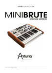
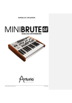
USER’S MANUAL Arturia Microbrute User’s Manual 1 PRODUCT AND PROJECT MANAGEMENT Glen T. DARCEY Bruno PILLET TABLE OF CONTENTS ELECTRONICS Yves USSON Bruno PILLET François BEST Laurent BARET Robert BOCQUIER DESIGN Axel HARTMANN (Design Box) Morgan PERRIER INDUSTRIALIZATION Nicolas DUBOIS MANUAL Glen DARCEY Morgan PERRIER SPECIAL THANKS TO: Frank Orlich, Jean-Michel Blanchet, Michael Hosker, Sébastian Rochard, Boele Gerkes, Antonio Rodriguez, Katsunori Ujiie, Howard Jones, Alex Theakston, Jim Cowgill, Drew Anderson, Ray Barbee, Keith Shocklee, Kevin Lamb, Jim Norman, Ryan Wood. 1 edition: July 2013 st Information contained in this manual is subject to change without notice and does not represent a commitment on behalf of ARTURIA. The hardware unit and the software product described in this manual are provided under the terms of a license agreement or non-disclosure agreement. The license agreement specifies the terms and conditions for its lawful use. No part of this manual may be produced or transmitted in any form or by any purpose other than purchaser’s personal use, without the explicit written permission of ARTURIA S.A. All other products, logos or company names quoted in this manual are trademarks or registered trademarks of their respective owners. © ARTURIA S.A. 1999-2013, all rights reserved. ARTURIA S.A. 30, chemin du vieux chêne 38240 Meylan France http://www.arturia.com Arturia Microbrute User’s Manual 2 TABLE OF CONTENTS 1 Introduction ....................................................................................................................... 5 2 Installation .......................................................................................................................... 9 Usage Precautions....................................................................................................................... 9 Register your Instrument............................................................................................................ 11 Connecting the MicroBrute to the World ................................................................................. 11 Warm-Up and General Tuning.................................................................................................. 13 3 Quickstart ......................................................................................................................... 14 Create your first sound: the “basic patch” .............................................................................. 14 Introducing The Oscillator ......................................................................................................... 15 More Oscillator options .............................................................................................................. 15 Combine sounds ........................................................................................................................ 15 Introducing The Filter ................................................................................................................. 16 Low Pass Filtering ........................................................................................................................ 16 High Pass Filtering ....................................................................................................................... 16 Band Pass Filtering ...................................................................................................................... 17 Filter Resonance ......................................................................................................................... 17 FILTER as an OSCILLATOR?......................................................................................................... 18 Brute Factor ................................................................................................................................. 18 Introducing The Envelope ......................................................................................................... 19 ENVELOPE TO VCA ..................................................................................................................... 20 Introducing The LFO................................................................................................................... 21 Introducing the Mod Matrix ...................................................................................................... 22 Introducing The Sequencer ...................................................................................................... 23 Recording A Basic Pattern ........................................................................................................ 23 Inserting Rests .............................................................................................................................. 23 Moving On ................................................................................................................................. 24 4 Synthesis Basics ............................................................................................................... 25 Analog synthesizer architecture .............................................................................................. 25 Oscillators................................................................................................................................... 25 Signal Modifiers.......................................................................................................................... 26 The Ultrasaw ................................................................................................................................ 26 The Pulse Width Modulator ....................................................................................................... 27 The Metalizer ............................................................................................................................... 27 Filter ............................................................................................................................................ 28 What is a filter?............................................................................................................................ 28 Filter types on MicroBrute: Low-pass, Band-pass, and High-pass ........................................ 28 Resonance or emphasis ............................................................................................................ 29 Voltage Controller Amplifier ..................................................................................................... 30 Modulators ................................................................................................................................. 30 Low Frequency Oscillator (LFO) ............................................................................................... 31 Envelope Generator .................................................................................................................. 31 Human Interface ........................................................................................................................ 32 5 Front Panel Features ........................................................................................................ 33 OSCILLATOR ............................................................................................................................... 33 The oscillator and its signal mixer ............................................................................................. 33 Saw and Ultrasaw ....................................................................................................................... 33 Square and Pulse Width ............................................................................................................ 33 Triangle and Metalizer ............................................................................................................... 34 The Overtone oscillator ............................................................................................................. 34 Arturia Microbrute User’s Manual 3 The Filter...................................................................................................................................... 35 Filter Modes ................................................................................................................................. 35 Cutoff ........................................................................................................................................... 35 Resonance .................................................................................................................................. 35 Brute Factor ................................................................................................................................. 36 ENV Amt (envelope amount) ................................................................................................... 36 KBD Tracking ............................................................................................................................... 37 Envelope .................................................................................................................................... 37 Envelope Amount ...................................................................................................................... 37 VCA switch .................................................................................................................................. 37 Attack slide.................................................................................................................................. 38 Decay slider ................................................................................................................................ 38 Sustain slider ................................................................................................................................ 38 Release slider .............................................................................................................................. 38 Envelope Settings via the MicroBrute Editor ........................................................................... 38 LFO .............................................................................................................................................. 38 Wave Select ................................................................................................................................ 39 Amount ........................................................................................................................................ 39 Rate .............................................................................................................................................. 39 Sync .............................................................................................................................................. 39 LFO Settings via the MicroBrute Editor ..................................................................................... 39 Mod Wheel ................................................................................................................................. 40 Mod to Cutoff ............................................................................................................................. 40 Mod to LFO Amt ......................................................................................................................... 40 Glide ........................................................................................................................................... 40 Mod Matrix ................................................................................................................................. 41 Modulations Sources .................................................................................................................. 41 Modulation Destinations ............................................................................................................ 41 General Controls ....................................................................................................................... 42 Keyboard ..................................................................................................................................... 42 Wheels.......................................................................................................................................... 42 Octave......................................................................................................................................... 42 Master Volume............................................................................................................................ 43 Sequencer.................................................................................................................................. 43 Pattern ......................................................................................................................................... 44 Play Mode ................................................................................................................................... 44 Rate .............................................................................................................................................. 44 6 Rear panel ....................................................................................................................... 46 Power supply.............................................................................................................................. 46 USB .............................................................................................................................................. 46 MIDI............................................................................................................................................. 46 Audio In ...................................................................................................................................... 47 Fine Tune .................................................................................................................................... 47 Audio Outputs ............................................................................................................................ 47 CV / GATE I/O ........................................................................................................................... 47 Get MicroBrute Connection...................................................................................................... 48 7 Legal Notes ...................................................................................................................... 49 No liability for consequential damages .................................................................................. 49 FCC Information (USA) .............................................................................................................. 49 Canada ...................................................................................................................................... 50 Europe ........................................................................................................................................ 50 Arturia Microbrute User’s Manual 4 1 Introduction Congratulations, and thank you for your purchase of the ARTURIA MicroBrute analog synthesizer. The MicroBrute is based on the award winning analog designs of its big brother, the MiniBrute. The MiniBrute became a modern classic by bringing excellent sound quality, user features and craftsmanship to the market with a price point that no others were able to match. The MicroBrute builds on this legacy and is designed to be another modern classic for anyone from the first time synth buyer to the experienced pro with a studio full of gear. SOFTWARE Since the late 1990s, ARTURIA has received acclaim from players and reviewers alike for designing state-of-the-art software emulations of the venerable analog synthesizers from the 1960s to the 1980s. From the Modular V, back in 2004, to Origin, a modular system of a new generation that we introduced in 2010; from Analog Factory Experience, the first hybrid synthesizer ever (debuted in 2008), to the Oberheim SEM V released at the end of 2011, our passion for synthesizers and sonic purity has given demanding musicians the best software instruments for professional audio production. Arturia Microbrute User’s Manual 5 HYBRID HARDWARE Overview of some of ARTURIA’s software, hardware and hybrid instruments After recreating so many legendary analog synthesizers by translating these classic instruments into sophisticated DSP algorithms, the time was right for ARTURIA to introduce an analog synth of its own, the MiniBrute. But reproducing analog circuitry is not the same as designing great-sounding analog circuits, so we enlisted the aid of Yves USSON — an extremely talented analog circuit designer and synthesizer enthusiast whose work spans three decades. Besides being a talented researcher in bio-molecular microscopy, his clones of the modules originally designed by Bob Moog, as well as ARP or EMS and his own designs, are highly renowned in the “modular” world and continuously produced under license by specialty manufacturers. Arturia Microbrute User’s Manual 6 What’s more, he’s always willing to share his considerable experience, and pass along his knowledge to others. All his schematics stay open to the D.I.Y.1 community; most of his works can be found on the “Yusynth” project website2, and he casts a long, and welcome, shadow on the major Internet forums devoted to analog fanatics. Yves USSON and a couple of wired friends Combining ARTURIA’s acclaimed savoir-faire in designing innovative musical instruments, and Yves’ deep knowledge and experience, both the MiniBrute and MicroBrute analog synthesizers have their roots in the 1970s yet incorporates the best of the 21st century. 1 D.I.Y. = “Do It Yourself” 2 http://yusynth.net Arturia Microbrute User’s Manual 7 We built the MicroBrute with the idea that many people need an easy to use synth for live and studio purposes. But an easy to use synth must still retain excellent sound quality and enough features to keep a sound designer busy for years. It is true that MicroBrute is simple to use and allows anyone to tweak sounds and make music without having to delve too deep into synthesis but it does not mean that the experienced user will not be impressed with the sound possibilities that this little powerhouse has. The pure analog oscillators with the newly designed OVERTONE PLL offer more raw tone generation options than many synthesizers in the $1000+ price range. The multimode Steiner-Parker filter is the same design that is found on the MiniBrute. The inventor, Nyle Steiner himself looked over our design and gave his stamp of approval. Many synthesizers with large price tags only give you one filter mode; MicroBrute gives you three. Add the MOD MATRIX patch bay, the multi wave LFO, USB, MIDI and CV/Gate interfaces and the exciting new STEP SEQUENCER and you have a product that meets or exceeds any other synthesizer in this price range, EVER! MicroBrute is all about top shelf sound quality, but with a musical interface that will not intimidate and a price that will not break the bank. MicroBrute is truly a musical instrument. We loved designing it, building it, and now, playing it. We hope you will share our enthusiasm, and find inspiration in its sounds. Arturia Microbrute User’s Manual 8 2 Installation Usage Precautions The MicroBrute uses an external power adapter. Do not use any power supply or adapter other than the one provided by Arturia and specified in this manual. ARTURIA accepts no responsibility for damage caused by use of an unauthorized power supply. WARNING Do not place this product in a place or position where one might walk on, trip over, or roll anything over power cords or connecting cables. The use of an extension cord is not recommended. However if you must use one, make sure that the cord has the ability to handle the maximum current needed by this product. Please consult a local electrician for more information on your power requirements. This product should be used only with the components supplied or recommended by ARTURIA. When used with any components, please observe all safety markings and instructions that accompany the accessory products. SPECIFICATIONS SUBJECT TO CHANGE The information contained in this manual is believed to be correct at the time of printing. However, ARTURIA reserves the right to change or modify any of the specifications without notice or obligation to update existing units. IMPORTANT Always follow the basic precautions listed below to avoid the possibility of serious injury or even death from electrical shock, damages, fire or other risks. The product used either alone or in combination with an amplifier, headphones or speakers, may be able to produce sound levels that could cause permanent hearing loss. DO NOT operate for long periods of time at a high level, at a level that is uncomfortable, or a level that exceeds prevailing safety standards for hearing exposure. If you encounter any hearing loss or ringing in the ears, consult an audiologist immediately. It is also a good idea to have you ears and hearing checked annually. Arturia Microbrute User’s Manual 9 NOTICE Use only the provided AC adapter, as specified by ARTURIA. Read and understand all the instructions. Always follow the instructions on the instrument. The manufacturer’s warranty does not cover service charges incurred due to a lack of knowledge relating to how a function or feature works (when the unit is operating as designed); reading the manual is the owner's responsibility. Please study this manual carefully and consult your dealer before requesting service. PRECAUTIONS INCLUDE, BUT ARE NOT LIMITED TO, THE FOLLOWING: Before cleaning the instrument, always remove the electrical plug from the outlet, as well as the USB cable. When cleaning, use a soft and dry cloth. Do not use gasoline, alcohol, acetone, turpentine or any other organic solutions; do not use liquid cleaner, spray or cloth that’s too wet. Do not use the instrument near water or moisture, such as a bathtub, sink, swimming pool or similar place. Do not place the instrument in an unstable position where it might accidentally fall over. Do not place heavy objects on the instrument. Do not block openings or vents of the instrument; these locations are used for ventilation to prevent the instrument from overheating. Do not place the instrument near a heat vent or any place of poor air circulation. Make sure the line voltage in your location matches the input voltage specified on the AC power adapter. Do not open and insert anything into the instrument, as this could cause a fire or electrical shock. Do not spill any kind of liquid onto the instrument. In the event of a malfunction, always take the instrument to a qualified service center. You will invalidate your warranty if you open and remove the cover, and improper testing may cause electrical shock or other malfunctions. Do not use the instrument when thunder and lightning is present. Do not expose the instrument to hot sunlight. Do not use the instrument when there is a gas leak nearby. ARTURIA is not responsible for any damage or data loss caused by improper operations to the instrument. ARTURIA recommends the use of shielded and less than 3 meters long cables for Audio, and ferrite equipped CV/Gate and USB cables. Arturia Microbrute User’s Manual 10 Register your Instrument Registering your instrument establishes your legal ownership, which entitles you to access the Arturia Technical Support service, and be informed of updates. Additionally, you can subscribe to the ARTURIA newsletter to be informed of ARTURIArelated news as well as promotional offers. Connect to your Arturia account via this URL: http://www.arturia.com/login If you do not have an account, create a new one. Once you have your account and are logged in, go to the section “My Registered Products”, and add the MicroBrute synthesizer by entering its serial number, as printed on the sticker located under the machine: Connecting the MicroBrute to the World Always power-off all audio gear before making any connections. Failing to do so may damage your speakers, the MicroBrute synthesizer, or other audio equipment. After completing all connections, set all levels to 0. Power on the various devices, with audio amplifier or monitoring system last, then raise the volumes to a comfortable listening level. Arturia Microbrute User’s Manual 11 Here is an overview of the MicroBrute synthesizer’s connectors: • Audio Input & Outputs..........6.35 mm (1/4'') mono jacks • Headphone Output…………3.5 mm (1/8'') miniature stereo jack • CV/Gate.................................3.5 mm (1/8'') miniature mono jacks • MIDI Input................................Standard MIDI DIN-5 • USB...........................................Standard USB type B • Power DC Input......................12 Volt, 1Amp, Center pin positive Arturia Microbrute User’s Manual 12 Warm-Up and General Tuning As with all true analog synthesizers, after being powered-on the MicroBrute needs a warm-up period of approximately five to ten minutes. This allows the oscillator to reach a stable operating temperature, which insures accurate oscillator pitch. Warm-up time depends on the external temperature; a colder ambient temperature will require longer warm-up times, while a hotter ambiance will result in shorter times. Once the synthesizer has reached its running temperature, tune it to pitch. Use an external tuner to check the instruments tuning; if needed, tweak the Fine Tune knob on the rear panel to tune the MicroBrute to the desired pitch. The MicroBrute has been designed for rock-solid pitch stability when operated in normal temperature and humidity conditions, at external temperatures between 20°C and 32°C in temperate areas. In practice, the MicroBrute provides satisfactory operation over a much wider temperature range, although extreme external temperatures or fluctuations can lead to longer stabilization time or erratic tuning. Arturia Microbrute User’s Manual 13 3 Quickstart This chapter provides the basic instruction that you will need to create your very first sounds with the MicroBrute. In subsequent chapters, we’ll get deeper into the sound design process so you can create more animated and complex sounds. Create your first sound: the “basic patch” Once your MicroBrute has been correctly connected to your sound system, set all the controls to the positions shown in Figure 1. This is going to be referenced many times over as the BASIC PATCH. Figure 1 Switch on your MicroBrute, there will be about a 5 – 10 second time with no sound. Once it is booted up, let it warm up to stabilize the pitch. You can of course use it before it is warmed up but the pitch WILL drift for the first few minutes. These settings (also called a PATCH) are very useful. This patch makes a good reference point to start doing sound design. Remember it and refer to it often. This will help you gain a better understanding of what each control does and how they interact with each other so that you will grow more rapidly in your skills. Now try playing some notes and listen to the sound. The sound of the basic patch is just that; BASIC. What you are hearing is the raw SAWTOOTH WAVE from the OSCILLATOR. Arturia Microbrute User’s Manual 14 Introducing The Oscillator The oscillator is the tone-generating center of the MicroBrute. The basic patch has the Sawtooth Wave turned up fully. Try turning the Sawtooth Wave down to 0 and turning up the Square Wave as shown in Figure 2 Figure 2 You will hear the sound go from a brighter, buzzy sound to a more rounded and hollow tone. Now try turning the Square Wave down and turn up the Triangle Wave. The sound will be even darker now. Turn the Triangle Wave down and turn up the Overtone level and listen to it. More Oscillator options The knobs directly above each of the waveform level knobs, adjust aspects of the sound of each waveform itself. Turn up one waveform level at a time and then try turning the knob directly above to hear how the sound changes. You can hear how varied the sounds can be. Combine sounds Now try turning up more than one level knob and mixing the sounds of different waveforms together. When you start mixing waveforms and adjust the wave modifiers above them, you start to hear the great variation of sounds that you can generate on the MicroBrute. Arturia Microbrute User’s Manual 15 Introducing The Filter Now that you have been playing with the OSCILLATOR and are familiar with some of the things it can do, return the knobs to the BASIC PATCH settings so that we can explore the FILTER section. The FILTER is just what it implies. It filters, or removes, aspects of the signal that is put into it. The Steiner-Parker filter, originally designed by Nyle Steiner, allows for wide ranging sounds and many sonic possibilities. Low Pass Filtering The BASIC PATCH has the FILTER set to full open in LOW PASS mode. This means that it is not affecting the sound of the OSCILLATOR at all. In LOW PASS mode, having the CUTOFF knob in the full clockwise setting, means that all frequencies will ‘pass’ through it. See Figure 3 Figure 3 With the BASIC PATCH set, play a note and listen to the sound as you turn the CUTOFF KNOB counter clockwise. You will hear the sound get darker and darker until it goes away totally. High Pass Filtering With the CUTOFF knob still all the way counter clockwise, move the MODE SWITCH to HP; See Figure 4. You should now hear the sound come back. This changes the filter to a High Pass Filter. Just as the name implies, it allows the HIGH frequencies to pass though. With the knob in the full counter clockwise position, the filter is allowing all frequencies above that setting to pass through it. Figure 4 Arturia Microbrute User’s Manual 16 Now press a key and try turning the knob clockwise and listen to the result. You will hear the sound get thinner and thinner sounding until it goes away completely at the top of the range. See Figure 5 Figure 5 Band Pass Filtering Now move the MODE switch to BP = Band Pass. If you move the CUTOFF knob you will hear the effects of the Band Pass Filter. This filter allows a range of frequencies both above and below the cutoff point to be passed. See Figure 6 Figure 6 Filter Resonance The RESONANCE control on the filter is one that emphasizes the frequencies that the CUTOFF is set to. If you reset your filter controls to the BASIC PATCH settings, we can do some sonic experiments to see how this affects the sound. Play a sound and turn the RESONANCE control to the position shown in Figure 7. You will probably not hear too much of a change to the sound. But with the resonance set as shown, play a sound and turn the CUTOFF knob counter clockwise. You will hear that famous ‘analog’ filter sweep type of sound. Experiment with different settings of the RESONANCE and CUTOFF controls to hear the sounds you can create. Once you have a good feel for the range of sounds you can get with this setting, change the MODE to HP and to BP and experiment with the CUTOFF and RESONANCE settings to see how varied the sounds become. Arturia Microbrute User’s Manual 17 Figure 7 FILTER as an OSCILLATOR? As you may have found out in the last section, turning the RESONANCE control up too high can produce some other pitches. This is called FILTER OSCILLATION. It is when the filter actually becomes an oscillator. With the RESONANCE at the maximum clockwise position, turning the CUTOFF control will vary the pitch that you hear. See Figure 8. Be careful as it can result in some high volume sounds coming out. Figure 8 Brute Factor The BRUTE FACTOR control can add some subtle grunge to warm up the low end on a sound or it can be cranked up to create some nasty, Brutal, sounds. BE CAREFUL AND TURN DOWN THE OUTPUT VOLUME BEFORE TURNING THE BRUTE FACTOR UP!! You will find that the BRUTE FACTOR knob and the influence it has on the sound will vary greatly based on the settings of the CUTOFF and RESONANCE knobs as well as the MODE switch. Figure 9 Arturia Microbrute User’s Manual 18 Introducing The Envelope The ENVELOPE will allow you to shape the FILTER CUTOFF, the VCA(output volume), and other parameters via the MOD MATRIX. Setup the BASIC PATCH again and we will experiment with the ENVELOPE and the FILTER CUTOFF. Now, change the FILTER and ENVELOPE setting to be the same as you see in Figure 10. Figure 10 The BASIC PATCH has the SUSTAIN value at the maximum setting which basically turns the envelope on full. Start off by moving SUSTAIN to the minimum setting and the DECAY slider to the maximum setting. To have the ENVELOPE affect the FILTER CUTOFF, you need to turn up the ENV Amt knob in the FILTER section. The ENV Amt knob can go either positive or negative. Let’s go with positive for now. You will want to turn the CUTOFF knob down to hear the effect. In Figure 10, we have the RESONANCE control up part way to make the effect more interesting. Press a key and listen to how it seems that the FILTER CUTOFF is being moved by itself. Reducing the DECAY slider will make the effect of the filter sweep go faster. If the DECAY is set too low, it is moving the CUTOFF so fast that you might just hear a click. Arturia Microbrute User’s Manual 19 ENVELOPE TO VCA The BASIC PATCH has the VCA (Voltage Control Amplifier) set to GATE, which means that the sound will come on when you press a key and will shut off when you release it. To control the LEVEL of audio using the ENVELOPE, move the VCA switch to the ENV position. Figure 11 Figure 11 Since the SUSTAIN slider is at the maximum setting and the ATTACK, DECAY and RELEASE settings are at the minimum settings, you will hear the same thing that you would hear with the VCA set to GATE. Now let’s shape the sound’s amplification envelope, which determines how the level changes over time when you play a note. Until now the Sustain level has been set to maximum, which results in an “electronic organ” sound that has no dynamics. By changing the ATTACK, DECAY and RELEASE parameters we can control how the sound fades in, sustains, and fades out. Set the SUSTAIN to the minimum setting, play with the ATTACK, DECAY and RELEASE settings, and listen to how they affect the sound. Figure 12 Figure 12 Arturia Microbrute User’s Manual 20 Introducing The LFO Now let’s add some movement to the sound. LFO is short for Low Frequency Oscillator. The LFO is routed to the Pitch of the OSCILLATOR by default. This routing is completed in the MOD MATRIX. The white dotted lines show the default setting. Figure 13 Figure 13 With the BASIC PATCH, the LFO’s output amount is routed through the MOD WHEEL. Play a note and increase the MOD WHEEL and you will hear the pitch start to wobble. To have the LFO bypass the MOD WHEEL, set the MOD WHEEL switch to CUTOFF. Figure 14. When you move this switch, the AMOUNT knob in the LFO section will determine the amount of modulation coming from the LFO. Figure 14 Change the LFO waveforms to hear the effect on the sound. You can also change the AMOUNT and the RATE controls to hear the effects they create. Arturia Microbrute User’s Manual 21 Introducing the Mod Matrix The MOD MATRIX allows you to route the modulation sources (ENVELOPE, LFO, and KEYBOARD CV). You can route the different sources to the destinations with the 1/8” mono jack PATCH CORD’s that come with the MicroBrute. As we said in the LFO section, the LFO defaults to being patched to the PITCH control. Using the BASIC PATCH, insert a PATCH CORD from the jack labeled LFO to the jack labeled FILTER. Now when you increase the MOD WHEEL, the LFO will change the FILTER CUTOFF. You will need to turn the CUTOFF knob down to hear the effect. As you can see, the ENVELOPE defaults to being routed to the METALIZER control. By putting a cord into a source or destination jack, you disconnect the hardwired routing. The MOD MATRIX has two output sources, ENV and LFO, and 6 input destinations 1. Triangle wave METALIZER 2. SAW animator rate 3. PULSE WIDTH of the SQUARE wave 4. SUB Overtone modulation 5. PITCH 6. FILTER Cutoff Any output can be routed to any input. Arturia Microbrute User’s Manual 22 Introducing The Sequencer The SEQUENCER is a fun and musical addition to the MicroBrute. It will allow you to program in phrases and patterns and play them back at different rates. Start off by setting up the BASIC PATCH. Recording A Basic Pattern Set the PLAY MODE switch to RECORD. Figure 15 Figure 15 Now start playing notes on the keyboard. When you start playing notes, it will erase the sequence that is in the currently selected memory. When you are finished, move the PLAY MODE switch back to OFF. To play a sequence, just move the PLAY MODE switch to PLAY and press a key. Now your sequence is playing back. You can transpose the sequence up and down by playing different pitches on the keyboard. Speed up and slow down the sequence by turning the RATE knob or pressing the TAP TEMPO button 3 times. Inserting Rests You have now made a sequence that has a continuous string of notes. Figure 16 While that is fun, it is more useful to have syncopated patterns. Arturia Microbrute User’s Manual 23 To create a pattern that has rests in it, simply press the TAP/REST button each time you want to place a rest. In Figure 17 you can see the result of the pattern if you were to press the TAP REST button between playing notes. Figure 17 There are a number of settings that can be accessed via the software editor. These features are described in detail in the separate MicroBrute Connection manual. Moving On If you have followed all the steps of this Quick Start you should be fairly familiar with how to make a sound and what some of the main features and functions do to modify the sound. If you are new to synthesizers, It is recommend that you do the quick start procedures one more time from the beginning and then do it once more in about a week or two. Doing this a few times will get you rapidly up to speed with how to use the MicroBrute. Arturia Microbrute User’s Manual 24 4 Synthesis Basics Your MicroBrute is a true analog synthesizer, this means that all sounds are produced by analog electronic circuits. No digital computer circuitry is involved in the tone generation, and filtering of the sound. This gives MicroBrute a huge and warm sound. Analog synthesizer architecture The analog sound production chain uses what is called ‘subtractive synthesis’. The basic sound generator, or oscillator, creates a tone with a rich harmonic content; the filter then “subtracts” harmonics to create new variations on the original timbre. Subsequent circuits (an envelope generator in conjunction with a VCA, or voltage-controller amplifier) alter the level in a precise way to create dynamics. Oscillators The oscillator is the circuit that produces the basic waveforms for sound creation. This device produces an electronic signal characterized by a repetitive, shaped pattern (called a waveform). Most analog synthesizers will provide some or all of the following basic waveforms: sine wave, triangular wave, sawtooth wave, square, and pulse waves. Figure 18 The different waveform shapes have different timbres. For example, the sine wave sounds dark and plain, while the sawtooth wave sounds very bright. The square wave sounds a bit like a clarinet and the pulse wave resembles an oboe. The Sine wave is a pure waveform, meaning that it is only made up of a fundamental frequency. The Saw, Square and Triangle are more complex waveforms and are made up of multiple sine waves — a fundamental sine wave that determines the base frequency, and sine waves representing higher harmonics (also called overtones or partials) of that frequency which, when added together, produce a unique timbre. Figure 19 These harmonics are an integer multiple of the fundamental frequency, i.e., the second harmonic is twice the fundamental frequency, the third harmonic is three times the fundamental, and so on. A good reference that many people know would be the drawbars on an organ. The drawbars increase the volume of sine waves that are tuned to the harmonic overtone series. When you increase the levels, you are making a pure tone into a complex waveform. Arturia Microbrute User’s Manual 25 Figure 19 The rate at which the oscillator oscillates creates the pitch. The oscillators in a synthesizer are no different than ones found on electrical test equipment, except that they can be put under VOLTAGE CONTROL. A music synthesizer allows you to change the pitch of the oscillator by using a voltage. In the case of MicroBrute, the keyboard, LFO, Envelope or external voltage source can be voltage control sources that affect the pitch. Signal Modifiers Signal modifiers (or wave-shapers) transform, shape or distort the oscillator’s basic signal to change their harmonic content. The MicroBrute provides three signal enhancers: The Ultrasaw builds two phase-shifted copies of the basic sawtooth signal. These copies have independent and ever-evolving phase shifts with respect to each other, and are eventually mixed with the sawtooth signal. This results in a lively, rich, and thick ensemble effect. Figure 20. On the MicroBrute you can control the Ultrasaw rate with the LFO, ENVELOPE or KEYBOARD CV OUT by patching it in the MOD MATRIX. Figure 20 Arturia Microbrute User’s Manual 26 The Pulse Width Modulator (or PWM) takes the square wave and changes the ratio between the time the waveform is at maximum or minimum. The square wave corresponds to a 50% Pulse Width (PW). The pulse width can be set over a wide range (50% to 90%) making it possible to create a wide variety of tones from hollow and rich to nasal and thin. Figure 21. On the MicroBrute, the pulse width control can be controlled by the LFO, ENVELOPE or KEYBOARD CV OUT by patching it in the MOD MATRIX Figure 21 The Metalizer takes the basic triangular waveform and “warps/folds” it to create very complex jagged waveforms that are rich in high harmonics. This results in “metallic” sounds that are ideal for harsher tones that fit well in dance music or lead sounds that need to cut through a mix. The Metalizer has a default connection to the ENVELOPE via the MOD MATRIX. By turning up the ENVELOPE AMOUNT control and turning up the METALIZER knob, you will hear the effect. It can also of course be controlled via the LFO or Keyboard CV. Figure 22 Figure 22 Arturia Microbrute User’s Manual 27 Filter What is a filter? In general, a filter follows the oscillator and signal modifiers (wave shapers), and alters the spectral content of the incoming sound. This can involve either removing (filtering out) or emphasizing (resonating) particular overtones. Filters are very important circuits whose design contributes greatly to the synthesizer’s overall sound and character. Filter types on MicroBrute: Low-pass, Band-pass, and High-pass A filter can operate in various ways or modes. In the MicroBrute the filter can operate either as a low-pass filter, a band-pass filter, or a high-pass filter. In low-pass mode, the spectral contents below a given cutoff frequency (set with the CUTOFF knob) remain unchanged, while harmonics above the cutoff frequency are attenuated. In other words, it is called low-pass mode because it passes the low frequencies below the cutoff and reduces the high frequencies above the cutoff. The correlation of attenuation to frequency determines the filter’s slope, which is measured in -dB/octave. The Low Pass filter on MicroBrute is called a 12dB per octave filter because every octave above the cutoff point is reduced by 12dB. Figure 23 In band-pass mode, the cutoff frequency becomes a band’s center frequency. Sound within this band remains unchanged, while harmonics below or above the band’s range are attenuated. Figure 24 Arturia Microbrute User’s Manual 28 In high-pass mode, partials above the cutoff frequency remain unchanged, while the partials below the cutoff are attenuated. Figure 25 The cutoff frequency in any of these filter types does not have to be static; controlling it with other devices like a keyboard (keyboard tracking), an LFO or envelope generator creates dynamically-changing and interesting timbres. Resonance or emphasis Figure 26 Resonance is a filter’s ability to amplify or emphasize partials that are close to the cutoff frequency, thus creating a peak in the spectral response. This parameter can be increased up to a point where the filter no longer acts like a mere filter, but starts to oscillate on its own. Arturia Microbrute User’s Manual 29 Voltage Controller Amplifier The VCA or voltage controlled amplifier generally follows the filter. The VCA behaves in a similar way as the volume control, except that it controls the level based on Control Voltage signals. The gain of the VCA is controllable by the GATE or ENVELOPE on the MicroBrute. The amplifier is primarily responsible for shaping a sound’s dynamics. Figure 27 Modulators Modulators provide signals that are designed specifically to control the behavior of oscillators, wave shapers, filters and amplifiers. For example, when you sing with vibrato, you are “modulating” your voice with a low-frequency change in pitch, typically around 5Hz or so. The tremolo circuit in a guitar amplifier modulates the amplifier’s level. Modulators are useful to create dynamic pitch changes, timbre sweeps, and level variations. The modulators in the MicroBrute are the LFO (low frequency oscillator), envelope generator, and even the keyboard can be considered as a modulator. Using the MicroBrute’s CV inputs and MOD MATRIX, modulators can also be provided by external sources that generate control voltage (CV) signals and gate signals that turn modulators or notes on and off. Arturia Microbrute User’s Manual 30 Low Frequency Oscillator (LFO) An LFO is very much like a regular oscillator except that it typically runs at a much lower frequency. The MicroBrute low frequency oscillator can produce various waveforms at sub-audio frequencies (0.1Hz up to 200Hz). In general the waveform options are sine or triangle, sawtooth, and square, waves. The amount, or output level of the LFO can be controlled before being fed to the target devices to make subtle or wider range sounds. Envelope Generator Contrary to an LFO, an envelope generator (or ADSR generator, for “Attack / Decay / Sustain / Release”) does not provide a repeating pattern but is something that starts at a certain time, runs its course and then ends. The time that an envelope starts its sequence of stages is normally triggered by the keyboard, a sequencer or the Gate input. Pressing down a key or sending a gate signal provides an evolving signal with four different stages: The ATTACK, DECAY, SUSTAIN and RELEASE The attack stage determines how long it takes for the envelope to go from zero to its maximum level. The attack time can be as short as 2.5ms or as long as 2.5 seconds. The decay stage begins when the attack stage reaches its maximum value. After the attack stage is finished the decay takes over and decreases from this maximum attack level down to a level set by the SUSTAIN parameter. The speed of this decay can vary from 2.5ms to 2.5 seconds. The sustain stage starts at the end of the decay phase, and remains at the sustain value as long as a keyboard key is held down or a gate signal remains full on. The sustain level is variable between zero (no sustain) and the envelope’s maximum value. With a SUSTAIN value set to the maximum level, you will not hear the DECAY stages effect because it will not have a level to decay too. Arturia Microbrute User’s Manual 31 Finally, the release stage starts upon releasing the key, and sets the amount of time for the level to decrease from the sustain level down to zero. Figure 28 Human Interface To play a tune with your synthesizer, as a player you need a player interface. The MicroBrute provides you with a two-octave, piano-type keyboard. Besides offering a way to play notes, this keyboard provides additional controls for adding expressiveness: • Velocity corresponds to the dynamics of your playing and can modulate multiple parameters. The MicroBrute will send velocity as a USB controller. It does not have internal velocity routing and does not respond to velocity however. • Transposition allows shifting the keyboard’s note range over six octaves. • Pitch bender allows adding real-time pitch changes, like bending strings on a guitar. • Modulation wheel allows applying real-time modulation changes to various parameters. For example, it could add vibrato or change the filter cutoff as you move it. • Sequencer automates the creation of repeating sequences of notes. Alternative ways of playing the synthesizer are available through MIDI control and external CV/GATE signals. Arturia Microbrute User’s Manual 32 5 Front Panel Features OSCILLATOR The oscillator and its signal mixer The oscillator delivers three basic waveforms: sawtooth, pulse, triangle wave and our new PLL Overtone oscillator. The bottom row of knobs on the oscillator are the level controls for each waveform. The upper row of knobs are waveshaper controls for each of the waves. The MicroBrute allows you to blend and mix the different waveforms to create more complex sounds. Saw and Ultrasaw The level of the Saw (sawtooth) waveform is controlled with the knob labeled with the saw icon. Turning it counter-clockwise completely mutes the signal, while turning it up increases the level. When the Ultrasaw knob is fully counter-clockwise, only the saw signal is audible. Turning this knob clockwise mixes more Ultrasaw sound in with the plain saw signal. The Ultrasaw consists of two copies of the plain saw; these can be modulated by patching the LFO to the SAW control in the MOD MATRIX. The phase shift of one copy is modulated at a constant rate (.5Hz), while the second copy’s phase shift modulation rate can be controlled with the SAW CV input Square and Pulse Width The level of the Square wave is controlled with the knob labeled with the square symbol. Turning it down completely mutes the signal and moving it up increases its level. When the Pulse Width knob is fully counter-clockwise it creates a 50% square pulse. Turning the Pulse Width knob clockwise transforms the square wave into an asymmetrical pulse whose width can be increased up to 90%. The pulse can also be modulated using the LFO, Envelope or Keyboard by using the PWM patch point in the Mod Matrix. Arturia Microbrute User’s Manual 33 Triangle and Metalizer The level of the Triangle wave is controlled by the knob labeled with the Triangle symbol. Turning it down completely mutes the signals and moving it up increases the level. Turning the Metalizer knob from fully counterclockwise to fully clockwise warps the triangle wave’s smooth, flute-like sound into complex, metallic-sounding waves. The wave warping/folding can also be controlled using the METAL input in the MOD MATRIX: it is normalized to be controlled by the envelope, the amount of which can be adjusted with the ENV Amt knob in the envelope section. The Overtone oscillator The Overtone oscillator level is controlled with the knob labeled Overtone. Turning it down completely mutes the signal and moving it up increases its level. The Overtone oscillator is a signal that is created from the main oscillator but it allows for pitches that are down one octave from the main or up a 5th above the main, creating either a sub-oscillator or second oscillator tuned up a fifth effect. This allows you to thicken up the sound greatly. Turning the SUB>FIFTH knob allows you to blend from the octave down and 5th up sounds. You can then modulate this control by patching the LFO or ENV to the SUB jack in the MOD MATRIX. This will greatly thicken up the sound even further. Arturia Microbrute User’s Manual 34 The Filter Filter Modes This selects among the three filter modes: LP (low-pass), BP (band-pass), and HP (high-pass). The LP mode is the most commonly-used, and provides sounds which are full/fat and round. The BP and HP modes provide thinner and harsher sounds. Cutoff This knob adjusts the filter’s cutoff frequency. The frequency range goes from below 20Hz when turned fully counter-clockwise up to 18kHz when fully clockwise. For example, in LP mode you can adjust a sound’s brightness. The filter alters the oscillators’ timbre via the three response modes described previously (LP, BP, HP). The cutoff can be controlled by the keyboard, the Envelope, the LFO (via the mod matrix) and the mod wheel. The MicroBrute filter is based on Nyle Steiner’s Sallen & Key architecture (designed in the 70s) and offers -12dB/octave slopes in LP and HP modes, and -6dB/octave slopes in BP mode. Resonance This knob lets you create a resonance peak at the cutoff frequency. Turning it clockwise emphasizes the partials at the cut-off frequency, and the sound becomes more aggressive. When the knob reaches its last quarter zone, the filter will start to oscillate on its own. However this oscillating behavior depends on the cutoff frequency; the MicroBrute filter oscillates within a range beginning around 350 Hz up to approximately 8 kHz. To extend the oscillation range, use the Brute Factor knob. Arturia Microbrute User’s Manual 35 Brute Factor The Brute Factor feature drastically alters the filter characteristics so expect highly unpredictable results at extreme settings. You have been warned! The Brute Factor is a special MicroBrute feature inspired by a common patch used on a famous vintage mono-synthesizer that connected the headphone output to the external audio input. The result is a kind of feedback loop that’s ideal for raspy and grungy sounds. This patch has been implemented internally to the MicroBrute, and is controlled by the Brute Factor knob. This knob’s normal position is fully counter-clockwise, which disables the Brute Factor; turning up the knob gradually adds distortion to the sound. For low Brute Factor settings, the distortion is smooth and gentle but becomes harsher as you turn up the knob. When turned up above about 75% of the way, the MicroBrute can go berserk and produce barely controllable, crazy feedback sounds. ENV Amt (envelope amount) The ENV Amt lets you control the amplitude and polarity of the envelope signals sent to modulate the filter cutoff frequency. At the 0 position (12 o'clock), no envelope modulation occurs. When turned counter-clockwise (below the 0 mark), the ENV Amt knob sends an increasing amount of the inverted ADSR envelope. When turned clockwise (beyond the 0 mark) the ENV Amt knob sends an increasing amount of the standard, positive-going ADSR envelope. This effect is additive so as you add ENV amount, you may need to turn the filter cutoff down to get the desired effect. Arturia Microbrute User’s Manual 36 KBD Tracking The filter cutoff frequency can also be keyboard-controlled. The KBD Tracking knob lets you adjust how the cutoff follows the keyboard. At the full Counter-clockwise position the keyboard CV will not affect the filter cut at all. With lower filter settings you will hear the sound get darker and darker as you play up the keyboard. To have the sound track with the notes you are playing and have the filter cutoff remain even across the scale, set the knob in about the 12 o’clock position. With the knob in the 12 o’clock position, it will open the filter at the same approximate amount as the keyboard goes in pitch. Turning the knob to the far right will make the filter open much faster across the range of the keyboard. Envelope The envelope is normally triggered by the keyboard GATE signal. It can also be triggered by other GATE sources such as the Sequencer or the rear panel’s external GATE IN jack. The required gate signal at the back panel is a standard 10V positive gate. This means that most modern modular synthesizers will trigger it properly. Envelope Amount The ENV Amount control will vary the output signal from the envelope. This allows you to attenuate it, so that you can control how much of the signal goes to the destination. To route the Envelope to a control destination, use the Mod Matrix. Note that this control does not affect the Filter’s Envelope Amount control as it is a separate feed. VCA switch The VCA GATE/Env switch allows you to select two options for controlling the output level of the MicroBrute. By selecting GATE, the VCA (Voltage control amplifier) will simply open and close based on the input from the keyboard, sequence or external gate source. You will not have any kind of change over time with the level of the Arturia Microbrute User’s Manual 37 sound. With the switch set to Env, you will then be able to control the level using the controls from the envelope. The type of sound that you are trying to get will determine the settings you choose. Attack slider – the Attack slider sets the duration of the envelope’s first stage. The Attack time ranges from 2.5ms seconds to 2.5 seconds. Decay slider – the Decay slider sets the duration of the envelope’s second stage. The Decay time ranges from 2.5ms to 2.5secs. Sustain slider - The Sustain slider sets the level of the envelope’s sustain stage. Release slider – The Release slider sets the duration of the envelope’s final stage that takes place after you release a key or once the GATE signal goes low. Depending on the filter section’s ENV Speed switch the Release time ranges from 5ms to 5secs. Envelope Settings via the MicroBrute Editor There are a number of settings for the envelope that determine how it operates. These settings can be accessed via the MicroBrute Editor Software. See the section of the manual for MicroBrute Editor for more information. LFO The LFO is a low frequency oscillator. It is the primary modulation source for the MicroBrute’s other sections. The LFO is designed to operate from approximately .1 Hz up to 200Hz. It can be used to create subtle pitch vibrato or can be pushed to the maximum to get wildly changing sounds. Arturia Microbrute User’s Manual 38 Wave Select The LFO offers several modulation waveforms that can be selected using the switch. The options are; square, sawtooth, and triangle waves. Amount The Amount knob regulates how wide the modulation coming from the LFO is. It allows you to attenuate the level of the signal to get more subtle effects. Rate The rate knob allows you to set the speed of the LFO. It allows for a range of .1Hz – 200Hz. When the LFO is sync’d to MIDI Clock (via the settings accessed in the MicroBrute editor software) or the Sequencer, the rate control will change between fixed time divisions of the incoming or Seq clock. These sync’d rates are: 4 measures, 2 measures, 1 measure, ½ note, ¼ note, The Rate and the LFO sync can be set within the MicroBrute Editor. In the editor, you can set whether the LFO is Free-running or Reset on each note. Free-running – a free running LFO will have a set rate that does not change. Reset – the LFO can reset to a default start point on each Note/Sequencer Gate. This allows you to have the LFO start at the same point on each note on message. Sync This will allow the LFO to run on it’s own clock (or external MIDI clock source) in the FREE setting or have it tied to the timing of the Sequencer with the SEQ setting. LFO Settings via the MicroBrute Editor There are a number of settings for the LFO that determine how it operates. These settings can be accessed via the MicroBrute Editor Software. Arturia Microbrute User’s Manual 39 Mod Wheel The Mod Wheel can be assigned to two different functions. The Mod Wheel switch, in the controls section, determines the Modulation wheel assignment. Mod to Cutoff The Mod Wheel is routed to the Cutoff frequency control. This, in effect, is the same as the Cutoff Knob but in a more user-friendly performance setup. Being that this works in conjunction with the Filter Cutoff control, there are some settings of the Cutoff that will end up with you not hearing any effect of moving the Mod Wheel. To hear a change, you may have to adjust the Cutoff control up or down. Mod to LFO Amt With the option LFO Amt, the Modulation Wheel controls the LFO modulation signal level. When it is at its minimum position (Min) the modulation destinations receive no LFO signal. The control also works in conjunction with the LFO Amount knob in the LFO section. If the LFO Amount is set to 0, then adding mod wheel will do nothing. You will need to have the LFO Amount control up to have the Mod Wheel control the LFO. Glide The Glide knob sets the amount of portamento (i.e., how long it takes for the pitch to glide from one note to another when notes are played on the keyboard or by the Sequencer). With this knob fully counterclockwise, there is no glide and the note pitch transitions instantly to the next note. Turning this knob clockwise increases the portamento effect. At the maximum setting, it takes approximately 4s to glide from the lowest C of the MicroBrute keyboard to the highest C (two octaves above). Arturia Microbrute User’s Manual 40 Mod Matrix The Mod Matrix allows for patching modulation sources to modulation destinations. The Jacks are standard 1/8” (3.5mm) mono jacks and all connections hold to the standard 1V per octave standard that most modern modular synthesizers support. When you patch a jack into one of the CV Outs, it will break the normal connection. The Matrix’s standard connections are ENV > Metal & LFO > Pitch. The CV Output should be able to drive 4 Inputs Modulations Sources The jacks under CV Out are considered Modulation Sources. These are the Envelope Out and LFO outputs. One other Modulation source is the Keyboard CV output on the Rear panel. They all output a signal that can control external synthesizers or be patched to Modulation Destinations within the MicroBrute. Modulation Destinations The jacks under the CV In section are all inputs. These can also be called Modulation destinations. The jacks are: Metal – controls the same parameter as the Metalizer knob. The Envelope output is the default connection to the input. Turning up the Envelope Amount knob will send the signal to the Metalizer control. Saw – this allows patching to the Saw animator of the Ultrasaw. One way to test this is to patch the LFO Out to the Saw in. Make sure the LFO Amount and the Ultrasaw Amount and Saw Level are turned up. Sub – this allows control over a modulation circuit in the Overtone circuit. It will allow you to modulate the Overtone waves and create some huge sounds. Try patching the LFO Out to the Sub in. Make sure the LFO Amount and the Overtone Level pots are turned up. Arturia Microbrute User’s Manual 41 Pitch – this controls the Pitch of the oscillator. By default, the LFO Output is patched to this to allow for LFO vibrato. Filter – This allows control over the Filter Cutoff control. Note that the filter section already allows for both Envelope and Keyboard controls apart from the Mod Matrix. PWM – This is the input for the Pulse Width control. General Controls Keyboard The MicroBrute keyboard covers a two-octave range, which can be extended using the Octave Down/Up buttons. The keyboard can also be used as a fully polyphonic MIDI controller for other devices via the rear panel USB jack. Wheels The MicroBrute features the two classic control wheels. The Pitch wheel position defaults to the middle of its range, and returns to its default position when released. This wheel creates a pitch bend effect, where the player can shift pitch smoothly up or down while playing a note. The amount of shift is proportional to the rotation of the wheel. The Range of the Pitch bend defaults to 2 semitones. The second wheel is the Modulation wheel. It sets the overall amount of modulation signal sent to targets selected by the MOD Wheel switch. Depending on the switch setting, it controls the Cutoff or the LFO amounts. Octave Arturia Microbrute User’s Manual 42 The Octave section transposes the MicroBrute keyboard over a wide pitch range. One LED among the five colored LEDs (-2 red,-1 orange, 0 green ,+1 orange,+2 red) is lit at a time and indicates the transposition octave. The default selection is 0 (green LED), where the leftmost C key corresponds to C2 (130.81Hz) and the rightmost C key corresponds to C4 (523.25Hz). To shift the keyboard up by one octave press the Up button. Pressing the Down button once shifts the keyboard down by one octave and the leftmost C is now C1 and the rightmost is C3. Pressing the Down button a second time shifts the keyboard down by one more octave. With the Down and Up buttons the MicroBrute can play notes from C0 (32.7 Hz) up to C6 (2093 Hz). Master Volume The Master Volume knob sets the MicroBrute overall output volume, which fits the standard +4dBu line level. To silence the MicroBrute, turn this knob fully counter-clockwise. Sequencer The Sequencer allows you to record a series of notes in and then it will play them back in the order that you played them in. The Sequencer on the MicroBrute is a stepsequencer that allows you to record the notes from the keyboard. It has a total of 8 sequences. Arturia Microbrute User’s Manual 43 Pattern This knob selects between the 8 patterns. Play Mode This selects between PLAY, OFF and RECORD. Play - In Play mode, the sequencer will play based on the Keymode. Keymode is set in the MicroBrute editor software. Off – This turns the Sequencer Off. Record – This puts the sequencer into Record mode. This will allow you to record over an existing sequence. If you move the switch to Record but then realize that you do not want to write over the current sequence, you can either move the switch back to OFF or select the sequence that you want to record over with the Pattern Knob. When you record your first note/rest, then you have written over the current sequence. Rate The Rate knob sets the sequencer’s clock rate from 30 bpm to 260 bpm. The red LED under the knob blinks in sync with the tempo beat. Internal Sync - With the Sync set to internal the Tempo knob acts as expected — its position sets the general BPM value. The Sync mode can be set using the MicroBrute Editor software. External sync - The Rate knob acts differently if MicroBrute detects an external MIDI clock on the MIDI Input or USB connector: An external MIDI clock will turn the Rate control into a time division control, where it acts as a performance-oriented divider/multiplier. Fully counterclockwise will set the sequencer to play back notes at 1 note per measure, at the fastest, clock-wise setting, it will play the steps back at 1/32nd notes. Divisions are: 1 measure, ½ note, ¼ note, 1/8th, 1/16th, 1/32nd. Arturia Microbrute User’s Manual 44 Tap / Rest The Tap /Rest button has two functions: 1. Tap Tempo 2. Inputting Rests when recording sequences. Tap Tempo – the Tap Tempo button will allow the user to manually set the rate of the sequencer by tapping the button in real time. The number of taps that get averaged to calculate the tempo can be set using the MicroBrute Editor software. Rest – The Tap Tempo button will act as a rest input when you are recording a sequence. When you are in record, pressing the Tap button between notes will allow you to skip a note. Figure 29 shows and example of the Rest being used to edit the rhythm in steps 3 and 7 of a pattern. Figure 29 Arturia Microbrute User’s Manual 45 6 Rear panel Power supply Arturia Microbrute User’s Manual 46 Arturia Microbrute User’s Manual 47 The Power button turns the power on/off. The DC connector receives the MicroBrute’s external power supply plug. Only connect the 12V DC, 1A, center positive power supply that came with your MicroBrute. Connecting any other power supply could damage the MicroBrute. USB The USB port allows interfacing with a personal computer. It can be used for MIDI communication, as well as editing some of the synthesizer internal parameters such as MIDI channel, sequencer settings, or updating the firmware, through the MicroBrute Connection software. MIDI The MIDI In jack lets your MicroBrute be controlled from other MIDI devices. You can use MicroBrute as a sound module and connect a full sized MIDI Keyboard, like our Arturia Keylab 49 or 61, if you want a wider playing range or if you just want full sized keys. If you are using MicroBrute as a sound module, use a MIDI cable to connect MicroBrute MIDI In connector to your external MIDI device’s MIDI Out connector. Audio In The Input Level potentiometer adjusts the amount of an external audio source (guitar, synth, drum machine, etc.) that can be plugged into the MicroBrute signal chain via the rear panel Audio Input jack. This makes it possible to process an external audio signal with the filter and amplifier; also note that this signal can trigger the envelopes. NOTE: this is a line level input. To use this with a guitar or microphone you will need to boost the levels with a pre-amp first. The Input Level knob is recessed so that it does not get in the way. Just push on the knob and it will pop out for adjustment. When finished, just push it back in. Fine Tune The Fine Tune knob provides precision adjustment of the oscillator pitch. The 12 o'clock position corresponds to the default tuning (i.e. A=440Hz) Arturia Microbrute User’s Manual 48 when you play the second rightmost A of the keyboard and the default Octave is selected. The full range of the Fine Tuning knob is from about -2 semitones to +2 semitones. The Fine-tune knob is recessed to prevent it from being bumped. Just press the knob and it will pop out, allowing for easy adjustment. Audio Outputs Connect the Line Out jack to an audio mixer, a computer’s sound card, or directly to an audio amplifier using a ¼” mono cable. You can connect a pair of ear buds or headphones to Phones output. The Master Volume knob on the front panel controls the output level of both these jacks. CV / GATE I/O The MicroBrute also connects with other analog devices (analog synthesizer, analog step sequencer, etc.) through a CV/GATE interface where CV means Control Voltage. The Gate In 1/8” jack allows other analog devices to trigger the MicroBrute envelopes. The main MicroBrute functions (i.e., filter cutoff, and oscillator pitch) are controlled by the Cutoff and Pitch jacks in the Mod Matrix. The MicroBrute can also control other analog devices. The Pitch Out 1/8” jack provides the CV produced by the MicroBrute keyboard as well as by the Pitch wheel. The keyboard’s GATE signal is also available on the Gate Out 1/4” jack. The Gate is a standard positive going 0-10V gate. The CV inputs and outputs are standard 1V per octave. Get MicroBrute Connection The “MicroBrute Connection” software and its dedicated User's Manual are freely downloadable from the ARTURIA website: www.arturia.com Arturia Microbrute User’s Manual 49 7 Legal Notes No liability for consequential damages Neither ARTURIA nor anyone else involved in the creation, production, or delivery of this product shall be liable for any direct, indirect, consequential, or incidental damages arising out of the use of, or inability to use this product (including without limitation, damages for loss of business profits, business interruption, loss of business information and the like) even if ARTURIA was previously advised of the possibility of such damages. Some states do not allow limitations on the length of an implied warranty or the exclusion or limitation of incidental or consequential damages, so the above limitation or exclusions may not apply to you. This warranty gives you specific legal rights, and you may also have other rights which vary from state to state. FCC Information (USA) DO NOT MODIFY THE UNIT! This product, when installed as indicated in the instructions contained in this manual, meets FCC requirements. Modifications not expressly approved by ARTURIA may void your authority, granted by the FCC, to use the product. IMPORTANT: When connecting this product to accessories and/or another product, use only high quality shielded cables. Cable (s) supplied with this product MUST be used. Follow all installation instructions. Failure to follow instructions could void your FFC authorization to use this product in the USA. NOTE: This product has been tested and found to comply with the limit for a Class B Digital device, pursuant to Part 15 of the FCC rules. These limits are designed to provide a reasonable protection against harmful interference in a residential environment. This equipment generates, uses and radiates radio frequency energy and, if not installed and used according to the instructions found in the users manual, may cause interferences harmful to the operation to other electronic devices. Compliance with FCC regulations does not guarantee that interferences will not occur in all the installations. If this product is found to be the source of interferences, which can be determined by turning the unit “OFF” and “ON”, please try to eliminate the problem by using one of the following measures: • Relocate either this product or the device that is affected by the interference. • Use power outlets that are on a different branch (circuit breaker or fuse) circuits or install AC line filter(s). • In the case of radio or TV interferences, relocate/ reorient the antenna. If the antenna lead-in is 300 ohm ribbon lead, change the lead-in to coaxial cable. Arturia Microbrute User’s Manual 50 • If these corrective measures do not bring any satisfied results, please contact the local retailer authorized to distribute this type of product. If you cannot locate the appropriate retailer, please contact ARTURIA. The above statements apply ONLY to those products distributed in the USA. Canada NOTICE: This class B digital apparatus meets all the requirements of the Canadian Interference-Causing Equipment Regulation. AVIS: Cet appareil numérique de la classe B respecte toutes les exigences du Règlement sur le matériel brouilleur du Canada. Europe Arturia Microbrute User’s Manual 51