1
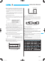
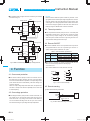
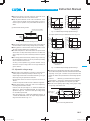
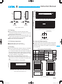
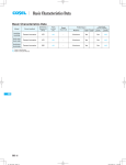
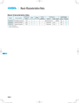
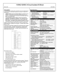
Basic Characteristics Data
Basic Characteristics Data
Model
Circuit method
Switching
frequency
[kHz]
CBS50
Forward converter
310
CBS100
Forward converter
370
CBS200
Forward converter
370
Input
current
[A]
Material
Single
sided
Series/Redundancy
operation availability
Double Series Redundancy
sided operation operation
-
Aluminum
Yes
Yes
*1
-
-
Aluminum
Yes
Yes
*1
-
-
Aluminum
Yes
Yes
*1
Rated
input fuse
Inrush
current
protection
Refer to
table No.1
PCB/Pattern
CBS350
Forward converter
370
-
-
Aluminum
Yes
Yes
*1
CBS450
Forward converter
370
-
-
Aluminum
Yes
Yes
*1
*1 Refer to Instruction Manual.
Table1. The value of input current (at rated input voltage and rated load)
Model
[A]
Output Voltage
1.8V
2.5V
3.3V
5V
12V
15V
24V
28V
32V
48V
CBS5024
1.2
1.6
2.0
2.5
2.4
2.4
2.4
2.4
-
-
CBS5048
0.6
0.8
1.0
1.3
1.2
1.2
1.2
1.2
-
-
CBS10024
2.5
3.2
4.1
5.0
4.8
4.8
4.8
4.8
-
-
CBS10048
1.2
1.6
2.0
2.5
2.4
2.4
2.4
2.4
-
-
CBS20024
3.8
4.8
6.1
7.6
9.6
9.6
9.7
9.7
-
-
CBS20048
1.9
2.4
3.0
3.8
4.8
4.8
4.8
4.8
-
4.8
CBS35024
-
-
-
-
15
-
17
17
17
14
CBS35048
-
-
-
-
8.4
-
8.2
8.1
8.2
8.2
CBS45048
-
-
-
-
-
-
10.6
10.5
9.3
-
CBS
CBS
CBS-12
CBS_E.indd 12
15.6.19 11:37:13 AM
DC-DC Converters Bus Converter.Power Module Type
Instruction Manual
1
Pin Configuration
CBS-14
2
Connection for Standard Use
CBS-14
3
Wiring Input/Output Pin
CBS-14
4
5
6
7
3.1
Wiring input pin
CBS-14
3.2
Wiring output pin
CBS-15
Function
CBS-16
4.1
Overcurrent protection
CBS-16
4.2
Overvoltage protection
CBS-16
4.3
Thermal protection
CBS-16
4.4
Remote ON/OFF
CBS-16
4.5
Remote sensing
CBS-16
4.6
Adjustable voltage range
CBS-17
4.7
Withstanding Voltage / Isolation Voltage
CBS-18
Series and Parallel Operation
CBS-18
5.1
Series operation
CBS-18
5.2
Redundancy operation
CBS-18
Implementation-Mounting Method
CBS-18
6.1
Mounting method
CBS-18
6.2
Stress onto the pins
CBS-18
6.3
Cleaning
CBS-19
6.4
Soldering temperature
CBS-19
6.5
Derating
CBS-19
6.6
Heat sink(Optional parts)
CBS-19
6.7
Addition of a Heat sink(Optional:FO)
CBS-20
Safety Considerations
CBS-21
CBS-13
CBS
DC-DC Converters Bus Converter . Power Module Type
1 Pin Configuration
Instruction Manual
¡Short the following pins to turn on the power module.
-VIN RC, +VOUT +S, and -VOUT -S
Reference: 4.4
4-Mounting hole
9 -VOUT
-VIN 4
”Remote ON/OFF”
4.5
”Remote sensing”
¡Only DC voltage can be applied to CBS Series. Applying AC voltage will damage the power module.
8 -S
(CBS50/100/200) CASE
3
(CBS350/450)NC
7 TRM
RC 2
6 +S
+VIN 1
5 +VOUT
¡The power module is designed for conduction cooling. Make
sure that heat sinks, fans, etc. are used for heat dissipation.
Refer to 6.5 ”Derating”
Fuse
+VIN
Fig.1.1 Pin Configuration (bottom view)
Cin
DC
input
Co +
3
4
5
6
7
8
9
CBS
No.
1
2
3
4
5
6
7
8
9
Pin Name
+VIN
RC
NC
CASE
-VIN
+VOUT
+S
TRM
-S
-VOUT
Mounting hole
Pin Name
+VIN
RC
NC
CASE
-VIN
+VOUT
+S
TRM
-S
-VOUT
Mounting hole
-VIN
-VOUT
CASE (CBS50/100/200) -S
C Y Mounting hole (CBS350/450)
Function
+DC input
Remote ON/OFF
No connection (CBS350/450)
Wiring base plate (CBS50/100/200)
-DC input
+DC output
+Remote sensing
Adjustment of output voltage
-Remote sensing
-DC output
Mounting hole
Load
RC
Table 1.1 Pin Assignment
No.
1
2
+S
+VOUT
+
Cin : External capacitor on the input side
Co : External capacitor on the output side
CY : Primary decoupling capacitor
Fig.2.1 Connection for Standard Use
3 Wiring Input/Output Pin
3.1 Wiring input pin
Reference
3.1 ”Wiring input pin”
4.4 ”Remote ON/OFF”
(1) External fuse
3.1 ”Wiring input pin”
¡When multiple modules get input voltage from a single front-end
power supply, a normal-blow fuse must be installed to each mod-
¡The input circuit of CBS Series does not come with a built-in fuse.
In order to protect the power module, a normal-blow fuse should
be installed to +VIN.
3.2
4.5
4.6
4.5
3.2
6.1
”Wiring output pin”
”Remote sensing”
”Adjustable voltage range”
”Remote sensing”
”Wiring output pin”
”Mounting method”
2 Connection for
Standard Use
ule.
Table 3.1 Recommended Fuses (Normal-Blow Type)
CBS20024
CBS35024
1R8/2R5/03/05 12/15/24/28
Rated current
6A
12A
20A
25A
30A
CBS20048
CBS35048
CBS5048 CBS10048
Model
1R8/2R5/03/05 12/15/24/28/48 CBS45048
Rated current
3A
6A
10A
12A
20A
Model
CBS5024 CBS10024
(2) Noise Filter/Grounding Capacitor
¡A grounding capacitor CY must be used to reduce the line noise
on the input line and stabilize the power module operation (Fig.
2.1). Note that resonance and inductance from the input line filter
¡The power module needs input and output connections as shown
in Fig. 2.1.
Reference: 3
6.5
CBS-14
”Wiring Input/Output Pin”
”Derating”
may cause the power module to become unstable.
¡An appropriate filter must be used if conformance to the conducted noise regulation is required or if surge voltage may be applied
to the unit. Please consult us for more details.
¡Install a grounding capacitor CY of at least 4700 pF as close to the
input pins as possible (within 50mm of the pins).
DC-DC Converters Bus Converter . Power Module Type
¡If the total capacitance of the grounding capacitor exceeds 15000
pF, the specified isolation voltage between input and output may
Instruction Manual
Input current [A]
Input voltage range
not be satisfied. In this case, either reduce the capacitance of the
grounding capacitor at the input or install a grounding capacitor to
the output.
There is no maximum limit to capacitance CY when the power
lp
module is used with an isolation voltage of less than 500VAC (1
Input voltage [V]
min.) between input and output.
Fig.3.2 Input Current Characteristics
(3) External Capacitor on the Input
(5) Reverse Input Voltage Protection
¡An external capacitor Cin must be installed between +VIN and
-VIN to reduce line noise and stabilize the power module operation (Fig. 2.1).
¡Avoid applying reversed-polarity voltage to the power module as it
will damage the power module. To protect the power module from
reversed polarity voltage, installing an external diode as shown in
Fig. 3.3 is recommended.
Capacitance
CBS50/100/20024:at least 68 F
CBS35024:at least 220 FX2
CBS50/100/20048:at least 33 F
CBS35048:at least 68 FX2
CBS45048:at least 68 FX2
Tc=-20 to +100C Electrolytic or Ceramic capacitor
(a)
(b)
+VIN
DC IN
-VIN
+VIN
DC IN
-VIN
Tc=-40 to +100C Ceramic capacitor
¡The capacitor must be installed less than 50mm of the power
module. As ripple current will flow through this capacitor, pay at-
3.2 Wiring output pin
tention to the ripple current rating of the capacitor.
¡If the power module is to be turned ON/OFF directly with a switch,
inductance from the input line will induce a surge voltage several
times that of the input voltage and it may damage the power module. Make sure that the surge is absorbed, for example, by connecting an electrolytic capacitor between the input pins.
(4) Input Voltage Range/Input Current Range
¡Install an external capacitor Co between +VOUT and -VOUT to
increase stability of output (Fig. 2.1).
Recommended capacitance of Co is shown in Table 3.2.
¡Choose a high frequency type electrolytic capacitor for Co. Output
ripple and rise time will be influenced by the capacitor’s ESR and
ESL and the wiring impedance.
¡Keep the input voltage ripple within the specifications below. Output ripple voltage will increase as these values increase.
Ripple voltage
Fig.3.3 Reverse Input Voltage Protection
¡As ripple current will flow through capacitor Co, pay attention to
the ripple current rating of the capacitor.
CBS50/100/200/35024:less than 2Vp-p
¡Install capacitor Co as close to the power module as possible
(within 50mm).
CBS50/100/200/35048:less than 4Vp-p
This is useful for reducing radiated noise and increasing stability
CBS45048:less than 4Vp-p
¡Make sure that the peak input voltage stays within the specified
input voltage range of the power module.
Ripple
voltage
Time
Fig.3.1 Input Voltage Ripple
t
Input voltage range
Input voltage [V]
¡Choose a front end power supply that can supply enough current
Ip (Fig. 3.2) for starting up the power module.
of the power module operation.
Table 3.2 Recommended Capacitance for External Output Capacitor Co ( F)
Base plate temperature : Tc=-20 to +100C
VOUT 1.8V/2.5V/3.3V/5V 12V
15V
24V
28V
32V
CBS50
2200
470
220
CBS100
2200
470
220
CBS200
2200
1000
470
CBS350
470
220
CBS450
220
Base plate temperature : Tc=-40 to +100C
VOUT 1.8V/2.5V/3.3V/5V 12V
15V
24V
28V
32V
CBS50
2200X2
470X2
220X2
CBS100
2200X2
470X2
220X2
CBS200
2200X2
1000X2
470X2
CBS350
470X3
220X3
CBS450
220X3
48V
330
48V
330X3
CBS-15
CBS
DC-DC Converters Bus Converter . Power Module Type
¡The specified ripple and ripple noise are measured by the method
introduced in Fig. 3.4.
CBS50/100/200
Remarks:
Note that devices inside the power module may fail when a voltage greater than the rated output voltage is applied from an exter-
50mm
Measuring board
+S
Instruction Manual
nal power supply to the output terminal of the power module. This
could happen in in-coming inspections that include OVP function
test or when voltage is applied from the load circuit. OVP can be
+VIN +VOUT
tested by using the TRM terminal. Consult us for details.
DC
input
Cin
+
Co
RC
+
0.1 F
Load
4.3 Thermal protection
-VIN -VOUT
¡Over Temperature Protection (OTP) is built in. If the base plate
temperature exceeds 100C, OTP will work, causing the output
4700pF
CASE
-S
voltage to drop. Output voltage can be recovered by shutting
Oscilloscope
BW : 20MHz
down DC input for at least one second or by turning RC off for one
CBS350
CBS350/450
second without shutting down the DC input.
50mm
Measuring board
+S
¡The remote ON/OFF function is incorporated in the input circuit
and operated with RC and -VIN. If positive logic control is re-
+VIN +VOUT
DC
Cin
+
input
Co
RC
+
0.1 F
4.4 Remote ON/OFF
Load
quired, order the power module with ”-R” option.
-VIN -VOUT
4700pF
Table 4.1 Remote ON/OFF Specifications
Mounting
-S
hole
Oscilloscope
BW : 100MHz
R
ON/OFF logic
1.5m 50W
Coaxial Cable
C R=50W
C=0.01 F
Fig.3.4 Method of Measuring Output Ripple and Ripple Noise
CBS
Standard
Negative
Optional
-R
Positive
Between RC and -VIN
L level(0 - 1.2V) or short
H level(3.5 - 7.0V) or open
L level(0 - 1.2V) or short
H level(3.5 - 7.0V) or open
Output voltage
ON
OFF
OFF
ON
¡When RC is at low level, a current of 0.5mA typ will flow out.
When Vcc is used, keep it within the following rage:
3.5 [ VCC [ 7V.
When remote ON/OFF is not used, short RC and -VIN.
4 Function
Vcc
RC
RC
4.1 Overcurrent protection
¡Over Current Protection (OCP) is built in and works at 105% of
the rated current or higher. However, use in an over current situation must be avoided whenever possible. The output voltage of the
power module will recover automatically if the fault causing over
-VIN
-VIN
Opto coupler
Transistor
RC
RC
-VIN
-VIN
IC
Relay
Fig. 4.1 RC Connection Example
current is corrected.
When the output voltage drops after OCP works, the power module enters a ”hiccup mode” where it repeatedly turns on and off at
a certain frequency.
4.2 Overvoltage protection
4.5 Remote sensing
(1) When Remote Sensing is Not Used
+S
+VOUT
¡Over Voltage Protection (OVP) is built in. When OVP works, output voltage can be recovered by shutting down DC input for at
least one second or by turning off the remote control switch for
one second without shutting down the DC input. The recovery
time varies according to input voltage and input capacitance.
CBS-16
+
Co
-VOUT
-S
Short at pin root
Fig. 4.2 When Remote Sensing is Not Used
Load
¡Keep the patterns between +S and +VOUT and between -S and
-VOUT as short as possible. Avoid a looping pattern. If noise enters the loop, the operation of the power module will become unstable.
(2) When Remote Sensing is Used
Instruction Manual
110
105
100
32,48
80
60
12,24,28
0
0
20
21
22
23
ADJUSTMENT RANGE [%]
¡When remote sensing is not used, make sure +VOUT and +S are
shorted, and that -VOUT and -S are shorted as well.
ADJUSTMENT RANGE [%]
DC-DC Converters Bus Converter . Power Module Type
48
115
110
105
100
32,48
80
60
12,24,28
0
0
36
INPUT VOLTAGE [V]
CBS35024OO
Wire as close as possible
38
40
42
INPUT VOLTAGE [V]
CBS35048OO
Fig. 4.4-1 CBS350 Output Voltage Adjustment Range
The output adjustment range for CBS450 is shown in Fig. 4.4-2.
+S
Co
Load
Fig. 4.3 When Remote Sensing is Used
¡Using remote sensing with long wires may cause output voltage to
become unstable. Consult us if long sensing wiring is necessary.
¡Sensing patterns or wires should be as short as possible. If wires
are used, use either twisted-pair or shielded wires.
¡Use wide PCB patterns or thick wires between the power module
and the load. Line drop should be kept less than 0.3V. Make sure
output voltage from the power module stays within the specified
range.
¡If the sensing patterns are shorted by mistake, a large current may
flow and damage the pattern. This can be prevented by installing
fuses or resistors close to the load.
As wiring or load impedance may generate oscillation or large
26.0
25.0
24.0
19.2
0
0
Output voltage will increase if the resistance between 1 and 2 is
reduced by turning the potentiometer clockwise.
Recommended values for external components are shown in
Table 4.2.
Consult us if the power module is used in a different configuration.
¡Output voltage between +VOUT and -VOUT can be adjusted by
connecting external resistors to TRM.
30.8
28.0
16.8
0
0
3640
32.0
25.6
0
0
76
36 40
INPUT VOLTAGE [V]
CBS4504832
¡The wiring to the potentiometer should be as short as possible.
As the ambient temperature fluctuation characteristics deteriorates
depending on the types of resistors and potentiometers used,
please use resistors and potentiometers of the following specifications:
Resistors ............. Metal film type, coefficient less than ±100ppm/C
Potentiometers ... Cermet type, coefficient less than ±300ppm/C
¡When output voltage adjustment is not required, open TRM.
¡Note that, when adjusting output voltage, setting output voltage
too high may cause OVP to work.
+S
+VOUT
20024 or 36 - 40VDC with CBS50/100/20048, the output voltage
for 1.8/2.5/48V output models.
-
Control Amp. of
rated voltage
range becomes as shown in Fig. 4.4-1.
RA
3kW
2.5V
TRM 2
+
When input voltage is 20 - 22VDC with CBS35024 models or 36
- 40VDC with CBS35048 models, the output voltage adjustment
CBS
Fig. 4.4-2 CBS450 Output Voltage Adjustment Range
However, when the input voltage is 18 - 20VDC with CBS50/100/
adjustment range is 60 - 105% of the rated output voltage except
76
60
INPUT VOLTAGE [V]
CBS4504828
35.2
given in advance.
¡Output voltage can be adjusted by connecting an external potentiometer (VR1) and resistors (R1 and R2) as shown in Fig. 4.5.
32.2
INPUT VOLTAGE [V]
CBS4504824
fluctuations in output voltage, make sure enough evaluation is
4.6 Adjustable voltage range
57 60
38 40
OUTPUT VOLTAGE [V]
+
OUTPUT VOLTAGE [V]
-VOUT
-S
OUTPUT VOLTAGE [V]
+VOUT
RB
VOUT RB
1.8V 1.3kW
2.5V 1.8kW
3.3 - 48V
3kW
RC
1kW
R2
-VOUT
-S
R1
1
VR1
5kW
3
Fig. 4.5 Connecting External Parts
CBS-17
DC-DC Converters Bus Converter . Power Module Type
Table 4.2 Recommended Values of External Resistors
No.
VOUT
1
2
3
4
5
6
7
8
9
10
1.8V
2.5V
3.3V
5V
12V
15V
24V
28V
32V
48V
Adjustable range
VOUT±5%
VOUT±10%
R1
R2
R1
R2
1.8kW
6.2kW
1.6kW
3.6kW
2.7kW
7.5kW
2.4kW
4.7kW
2.4kW
2.4kW
5.6kW
5.6kW
18kW
18kW
24kW
24kW
11kW
6.8kW
43kW
39kW
51kW
47kW
56kW
56kW
82kW
82kW
Instruction Manual
¡Even a slight difference in output voltage can affect the balance
between the values of I1 and I2.
Please make sure that the value of I3 does not exceed the rated
current of a power supply.
I3
the rated current value
6 ImplementationMounting Method
6.1 Mounting method
4.7 Withstanding Voltage / Isolation Voltage
¡When testing the withstanding voltage, make sure the voltage is
increased gradually. When turning off, reduce the voltage gradually by using the dial of the hi-pot tester. Do not use a voltage tester
with a timer as it may generate voltage several times as large as
the applied voltage.
¡When multiple power modules are used side by side, position
them with sufficient spaces to allow adequate air ventilation so
that the aluminum base plate temperature of each power module
will remain within the temperature range shown in the derating
curves (Fig. 6.2).
¡Do not pass the DC input pattern underneath the power module
as this will increase conducted noise. Place the DC input pattern
away from the power module.
5 Series and Parallel
Operation
Do not pass the DC output pattern underneath the power module
as this will increase output noise. Place the DC output pattern
away from the power module.
¡High frequency noise is radiated from the power module. When
mounting the power module on a PCB, leave a copper pattern
on the PCB to let it act as a shield and connect this pattern to the
CASE pin (CBS50/100/200) or the mounting hole.
¡Multiple CBS units can be used in series. Keep the output current
less than the smallest specified rated current of the modules connected in series. Make sure the current flown into the power module will not exceed the rated current.
(a)
ing a M3 tap on the heat sink. In case of CBS350/450, make sure a
mounting hole will be connected to a grounding capacitor CY.
Table 6.1 Mounting Hole Configuration
Load
Power
Supply
Power
Supply
Power
Supply
5.2 Redundancy operation
I3
¡Input and output pins are soldered onto the internal PCB. Do not
bend or pull the leads with excessive force.
¡As unexpected stress may be applied to the pins, set the diameter
of the PCB mounting hole at 3.5mm.
¡As unexpected stress may be applied to the pins from vibration
or shock, fix the power module by using the mounting holes with
Load
-VOUT
-S
+S
+VOUT
¡Applying excessive stress to the input or output pins of the power
module may damage internal connections. Avoid applying stress
in excess of that shown in Fig. 6.1.
¡Parallel operation is not possible.
¡Redundancy operation is available by wiring as shown below.
I1
Mounting hole
M3 tapped
f3.4 thru
6.2 Stress onto the pins
Fig. 5.1 Examples of Series Operation
+S
+VOUT
Standard
Optional : -T
Load
Power
Supply
I2
-VOUT
-S
CBS-18
¡When a heat sink cannot be fixed on the base plate side, order the
power module with ”-T” option. A heat sink can be mounted by affix-
(b)
Load
CBS
5.1 Series operation
Fig. 5.2 Example of Redundancy Operation
screws to reduce stress.
¡Fix the power module to the PCB with the screws before soldering
the input and output pins to prevent the PCB pattern being damaged.
DC-DC Converters Bus Converter . Power Module Type
100
(85.7)
(83.3)
Load factor[%]
-VOUT
-S
TRM
-VIN
CASE
NC
RC
+S
+VOUT
+VIN
2
1CBS3502412,CBS3502448,CBS3504848
2Others (CBS350)
50
(15)
0
-40
+VOUT, -VOUT
-20
Others
Less than
19.6N(2kgf)
Less than
19.6N(2kgf)
Less than
19.6N(2kgf)
Less than
39.2N(4kgf)
Load factor[%]
Less than
39.2N(4kgf)
0
20
40
(85)
80
60
100 110
(75)
CBS450
50
(15)
0
Fig. 6.1 Stress onto Pins
1
Aluminum base plate temperature Tc [C]
100
Less than
39.2N(4kgf)
Instruction Manual
-40
-20
0
20
40
(85)
80
60
100 110
Aluminum base plate temperature Tc [C]
6.3 Cleaning
Tc:Measuring point
¡Clean the soldered side of the power module with a brush.
Prevent liquid from getting into the power module. Do not clean by
soaking the power module into liquid.
¡Do not allow solvent to come in contact with product labels or resin cases as this may change the color of the resin case or cause
Aluminum base plate
deletion of the letters printed on the product label.
¡After cleaning, dry the power modules well.
Fig.6.2 Derating Curve
6.4 Soldering temperature
6.6 Heat sink(Optional parts)
¡Flow soldering: 260C for up to 15 seconds.
¡Soldering iron (26W): 450C for up to 5 seconds.
¡The power module works with conduction cooling and needs heat
dissipation using heat sinks. Optional heat sinks are available for
CBS Series. Refer to Table 6.2 for details on the thermal resis-
6.5 Derating
tance of heat sinks.
¡Use the power modules with conduction cooling (e.g. heat dissipation from the aluminum base plate to the attached heat sink).
Fig. 6.2 shows the derating curves with respect to the aluminum
Table 6.2 Types of Heat Sinks Available
Size[mm]
No.
Model
1
2
3
4
5
6
F-CBS-F1
F-CBS-F2
F-CBS-F3
F-CBS-F4
F-CBS-F5
F-CBS-F6
base plate temperature. Note that operation within the hatched areas will cause a significant level of ripple and ripple noise. Contact
us for more information on cooling methods.
¡It is necessary to note thermal fatigue life by power cycle.
Please reduce the temperature fluctuation range as much as possible when the up and down of temperature are frequently generated.
Contact for more information on cooling methods.
W
D
12.7
12.7
25.4
25.4
38.1
38.1
57.9
58.4
57.9
58.4
57.9
58.4
61.5
61.0
61.5
61.0
61.5
61.0
Thermal resistance[C/W]
Convection
Forced Air
(0.1m/s)
7.5
4.6
3.0
Style
Horizontal
Vertical
Horizontal
Refer Fig.6.4
Vertical
Horizontal
Vertical
W
W
2
1
100
Load factor[%]
H
1CBS200O12,15,24,28,48
2Others (Excluding CBS350/450)
50
D
D
0
-40
-20
0
20
40
60
(85)
80
100 110
Aluminum base plate temperature Tc [C]
H
H
Horizontal
Vertical
Fig.6.3 Heat Sink Types
CBS-19
CBS
DC-DC Converters Bus Converter . Power Module Type
¡Derating curve characteristics with respect to aluminum base plate
temperature are shown in Fig. 6.6. Measure the temperature of
6
5
the base plate in a location away from direct airflow (A). Note that
F-CBS-F1/F2
F-CBS-F3/F4
F-CBS-F5/F6
4
3
operation within the hatched areas will cause a significant level of
ripple and ripple noise.
2
100
2
1
0
0.0
0.5
1.0
1.5
2.0
Wind velocity(m/s)
2.5
3.0
Load factor[%]
Thermal resistance(C/w)
Instruction Manual
1CBS200 12, 15, 24, 28, 48
2Others (Excluding CBS350/450)
50
0
-40
Fig.6.4 Thermal Resistance of Heat Sink(Forced Air)
1
(95)
0
20
40
60
80 90 100 110
Aluminum base plate temperature Tc[ C ]
-20
Fig. 6.6 Derating Curve Characteristics
6.7 Addition of a Heat sink(Optional:FO)
Air
¡Heat sink pre-attached models are also available.
(Except CBS350/450)
Table 6.3 Types of Heat Sink Pre-Attached Models Available
Option
F1
F2
F3
F4
F5
F6
Size[mm]
Weight
Style
[g]
H
W
D
26.5 58.7 62.5
Horizontal
150 or less
26.5 59.5 62.0
Vertical
39.2 58.7 62.5
Horizontal
170 or less
39.2 59.5 62.0
Vertical
52.0 58.7 62.5
Horizontal
185 or less
52.0 59.5 62.0
Vertical
A
W
W
CBS
Heat sink
type name
F-CBS-F1
F-CBS-F2
F-CBS-F3
F-CBS-F4
F-CBS-F5
F-CBS-F6
D
D
Fig. 6.7 Measuring Point
Mounting hole
H
H
Horizontal
7mm max
¡Make sure that PCB mounting screws do not touch the heat sink
mounting screws.
Vertical
Fig. 6.5 Dimensions of Heat Sink Pre-Attached Models
PCB
M3(Mounting screw)
Fig. 6.8 PCB Mounting Screw Dimensions
CBS-20
DC-DC Converters Bus Converter . Power Module Type
Instruction Manual
7 Safety Considerations
¡To apply for safety standard approvals with the power module, the
following conditions must be met. Consult us for more details.
¿The power modules must be used as a component power supply
in end-use equipment.
¿Neither basic isolation nor double/reinforced isolation is provided
across input, output and the base plate of the power module. If
the power module is to be used with input voltage of more than
60VDC and needs basic or double/reinforced isolation, the required isolation must be provided in the construction of the final
product.
¿Use external fuses that comply with safety standards at the in-
put.
CBS
CBS-21