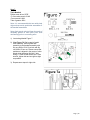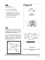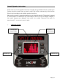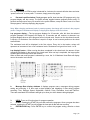
1
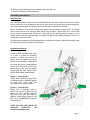
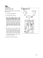
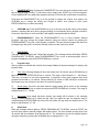
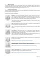
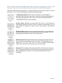
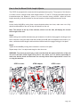
User’s Product Manual LifeCORELC-CD550 Center Drive Elliptical Introduction Congratulations on your purchase of the CD550 Center DriveElliptical. This product has been designed and manufactured to meet the needs and requirements of domestic use. By Choosing your CD550 Elliptical, you have made a wise decision that will improve the health of you and your family. Being fit and healthy will improve your energy level and your quality of life. Cardiovascular training is vital for all ages and the CD550 Elliptical provides a more effective workout, producing better results, and will encourage you to reach your fitness goals and maintain the body you have always wanted. In order to make your experience with LifeCORE the best it can be, please review the enclosed user’s manual prior to assembly and first use. Be sure to keep the instructions for reference and/or maintenance. We also offer a complete line of fitness equipment; please take a moment to review our other excellent products at www.LifeCOREfitness.com. Should you have any questions, please contact us. Your feedback and ideas about your experience with LifeCORE are also very important to us. Write to us at: LifeCORE Fitness Inc. 2575 Pioneer Ave. Suite 101 Vista, CA92081 We wish you lots of success and fun while training! Purchaser’s Reference Information Serial Number is located on the frame Please send in the attached warranty card and a copy of the original receipt or register online at www.LifeCOREfitness.com within (10) days of purchase to register your product with LifeCORE Fitness. Page | 1 Table of Contents Introduction……………………………………………………………………………………............. 1 Purchaser’s Reference Information …………………………………………………………………. 1 Table of Contents……………………………………………………………………………………… 2 Safety instructions and Warnings……………………………………………………………………. 3 Assembly Instructions ………………………………………………………………………………… 4 Console Operation Instructions ……………………………………………………………………… 12 Monitoring Your Heart Rate …………………………………………………………………………. 19 Heart Rate Monitoring Devices ……………………………………………………………………… 20 How to Use the Manual Stride Length Adjuster …………………………………………………… 22 Care and Maintenance ………………………………………………………………………………. 23 Warranty Card…………………………………………………………………………………………. 24 Page | 2 Safety Instructions & Warnings The CD550 Elliptical is designed and manufactured to meet or exceed all domestic and international safety standards. However, certain precautions need to be followed when operating any exercise equipment. General safety instructions: 1. It is important to consult your physician before any exercise program. 2. Pregnant women should consult with their physician before beginning any exercise program. He/she can help determine the exercise program that is the most appropriate for your age and physical condition. 3. If you experience dizziness, nausea, chest pains or other abnormal symptoms during exercise, stop the exercise session immediately. Consult your physician before continuing your exercise. 4. Keep children away from the equipment. Hands and feet may get caught in the pedals or other moving parts, which could result in serious injury. 5. No more than one person should ever use the product at a time. 6. Pets should never be allowed near unit. 7. Always wear proper clothing and shoes when exercising. Drink plenty of fluids when exercising. 8. Always stretch and warm up before starting any exercise program. 9. Never operate this unit if it is damaged or broken. Contact your authorized dealer for service. 10. Place your equipment on a solid, level surface when in use. 11. Place your unit in an area with enough clearance to operate the equipment. 12. Make sure all components are fastened securely at all times. Product safety instructions: 1. Start your exercise program gradually. Exercise only for a few minutes the first day to let your body adjust to the new exercise. 2. Slowly increase your exercise time and intensity over the first two weeks.If you increase your intensity too rapidly, or fail to warm up properly, you can increase the risk of injury. 3. Use of this machine with worn or weakened parts, may result in injury to the user. We strongly suggest replacing it immediately. Use only the accessory attachments recommended by the manufacturer. 4. Unit maximum weight limit is 350LBS 5. It is recommended the unit be plugged into a surge protector. 6. Whenever mounting or dismounting from the exercise machine, make sure that the unit is not in motion and use caution to prevent injury. Use the handlebars or a helper whenever additional stability is required. 7. Never place any open containers of any type directly on the unit, only containers with lids are recommended to be used with the appropriate water bottle holder. 8. Keep machine clear of any obstructions, heavy machinery, and never place objects on or against machine. 9. Do not place machine in an area of high voltage or electromagnetic fields. 10. DANGER: Always unplug the power cord before performing maintenance. 11. Failure to follow these instructions will void the units warranty and the manufacturer or distributor assumes no responsibility for personal injury or property damages related to the product if unit is ever used incorrectly or for reasons other than exercise. Page | 3 12. Perform proper maintenance as recommended in this manual. 13. Save this manual for future reference. Assembly Instructions Assembly Tips The LifeCORECD550 is made from the best materials and has been tested and received a quality control review prior to its packaging to ensure the correct parts and proper fitting of each component. This machine was designed to limit the amount of assembly needed by a consumer. Before assembly of your product, distinguish a proper and appropriate location for the unit where there is easy access to an electrical outlet with a surge protector. Unpack the box in a clear work area to allow smooth assembly. Remove all of the parts from the packing material; however, do not discard packing material until assembly is complete. Double check packing materials to ensure no missing parts were left behind. Note that some hardware may be preassembled to components in order to help with assembly; tools have also been provided to assist with assembly. Assembly Assistance In each CD550 assembly pack, there is a tube of grease for assembly purposes. A small even amount of grease must be applied to the pivot points during assembly. Apply about two finger tips worth of multi-purpose grease onto the bottom of both foot pedal tubes in the area that makes contact with the roller wheel. (Parts #2CU8 Shaft Wheel w/ball bearing) Figure 3 Figure 3 – Green Arrows During Step 3 assembly, apply about a finger tips worth of assembly grease on each pivot point, shaft and bearings prior to connecting arms. Figure 5 Figure 5 – Green Arrows During Step 5 assembly, apply a small even amount of grease to the pedal tube and handrail assembly tube pivot point on each side. In addition, evenly apply grease to the M10 * 81.5 Hex Bolt before joining the two assemblies. Apply Grease NOTE: DO NOT USE WD-40 OR SILICONE SPRAY-This will increase squeaking noise. Page | 4 Getting Started Unpack the box in a clear location, remove all packaged parts from the box and lay each part out on the floor. Double check all packaging material for missing pieces, do not dispose of any packing material until assembly is complete and unit is working properly. The final location of the machine should be placed on a clean level surface near an electrical outlet. Hardware Bags - Locate all hardware bags for assembly. Bags will be labeled Figure 1 through Figure 8. Tools have been provided to assist with product assembly. If you are missing any parts, assembly bags or need assistance with assembly please call LifeCORE Fitness at 1-888-815-5559. Tools Required: 17mm socket wrench: 2JAX 17mm wrench: 2JAW Philips Screw driver: 2E3E 4mm Allen wrench: 0J3P 5mm Allen wrench: 0J3Q 6mm Allen wrench: 2JC7 Tube of grease: 2K81 Page | 5 Step 1: Tools Needed: 6mm Allen wrench: 2JC7 Note: It is recommended that two adults help during this step. One person holds the upper support tube assembly while another connects the upper support tube wires to the lower wire cables. Note: Ensure that all wires are properly connected inside console tube. Be careful to not pinch wires. Additional help maybe needed to help line up holes to frame. 1) Locate bag labeled Figure 1. 2) Locate upper support tube assembly. 3) Before attaching upper support tube to the main frame, connect each wire together. 2XKB 7 pin connection to 2XJA 4) (See Figure 1) Note: Push down or lift up on support tube to help align holes. Secure upper support tube assembly to frame using Qty eight M8X1.25-12mm hex head bolts and Qty eight 8x15.5 washers on the right side and left side. Using a 6mm Allen wrench, tighten bolts secure. Slide black rubber boot over bolts. Page | 6 Step 2: Tools Needed: 5mm Allen wrench: 0J3Q 4mm Allen wrench: 0J3P Note: It is recommended that two adults help during this step. 1) Locate bag labeled Figure 2. 2) Locate right and left side rails. 3) (See Figure 2)Note: Apply a small amount of assembly grease to the inner top rails to help slide rails easily into place. Locate left side rail. Insert lower left side rail down into the lower portion first. This will allow the top portion to slide into position easier. Slide the rail into the upper support tube. Attach upper support tube with Qty two M6x1-16 short bolts and Qty two 6x13 washers to secure rail. 4) Next, attach the lower portion with Qty two M6x1-50 long half threaded bolts and Qty two 6x13 washers. Additional help may be needed to push down on rail to help align holes. Using a 5mm Allen wrench, tighten the top bolts and use a 4mm Allen wrench to secure to bottom bolts. 5) Repeat same steps for right side. Page | 7 Step 3: Tools Needed: Philips screw driver: 2E3E 6mm Allen wrench: 2JC7 Note: Be careful not to pinch any wires. 1) Locate bag labeled Figure 3. 2) Locate console mast and slide console mast into upper support tube assembly, make sure computer cable wire slides down straight and does not get pinched. 3) Connect the computer cable wire coming from the console mast to the upper support tube middle wire on the right side of the machine. 4) (See Figure 3) Using Qty two M8x1.25-50 bolts thread those through the console mast and use a 6mm Allen wrench to tighten bolts. 5) Locate console and connect all the wire connectors properly. 6) Place the computer console on the console mast. Make sure the wires fit inside computer and computer console sits flat on the console mast. 7) Grab the Qty. four M5x0.8-12 screws, and using a Philips screw driver secure console. Step 4: Tools Needed: Philips screw driver: 2E3E 1) Locate the console mast cover and install cover to the machine with a Philips screw driver using Qty four M5x8 screws. Page | 8 Step 5: Tool Needed: None. 1) Locate bag labeled Figure 5 2) Locate the right and left Handrail Linkage Assemblies. 3) (See Figure 5) Unscrew the T-grip and discard the plastic space washer. Slide the left handrail linkage assembly on to the adjustment arm frame. 4) Put washer & T-grip back in place and tighten the T-grip. 5) Repeat for right Side. Step 6: Tools Needed: 6mm Allen wrench: 2JC7 Note: Additional help may be needed to help align holes on top and bottom. 1) Locate bag labeled Figure 6. 2) (See Figure 6) Lift and place left handrail linkage assembly onto shaft sleeve and align holes. Additional help may be needed to help align holes. Secure linkage to unit using Qty four washers & M8x1.25-12 hex bolts, two on top and two on the bottom. 3) Use a 6mm Allen wrench to tighten the M8x1.25-12 hex bolts on top and bottom as tight as possible to prevent the bolts from coming loose. 4) Repeat same steps for right side. Page | 9 Step 7: Tools Needed: Philips screw driver: 2E3E 17 mm socket wrench: 2JAX 17mm wrench:2JAW Tube of grease: 2K81 Note: It is recommended that two adults help align and secure the pedal tube assemblies to the handrail assemblies. Note: Apply evenly about a finger tips worth of assembly grease on each pivot point shaft and bearings prior to connecting arms. 1) Locate bag labeled Figure 7. 2) (See Figure 7 & 7a) Locate left pedal tube assembly. Secure pedal tube assembly to the handrail assembly with Qty one M10x1.5-81.5 hex bolt and Qty one M10x1.5 hex nut. Please ensure that pedal arm is aligned in the center of roller wheel while tightening M10x81.5 bolt. Using a 17mm socket wrench and 17mm wrench, tighten bolt and nut tight as tight as possible. 3) Repeat same steps for right side Figure 7a Page | 10 Step 8: Tools Needed: 6mm Allen wrench: 2JC7 1) Locate bag labeled Figure 8. 2) Locate left and right handlebars. 3) (See Figure 8) Attach left handlebar to handlebar assembly using Qty three M8x16mm hex bolts. Using a 6mm Allen wrench, tighten hex bolts tight. 4) Repeat for other handlebar. Step 9: Plug the AC adaptor into a power outlet and into the machine. The AC inlet is located on the user left side of the machine. Only a DC 9V 1500mA that comes with the unit should ever be used to power the machine. Once assembly is complete; if needed, tighten or loosen the levelers on the bottom of the machine to prevent the machine from wobbling and to make the machine stable. Tighten the leveler nut on top of the lever to prevent them from moving. AC Adapter Location Congratulations! You have completed assembly of your CD550 Elliptical Page | 11 Console Operation Instructions Please read the console operation instruction thoroughly and get familiar with the console layout. Practice using this console before you start in order to get a better understanding of the functions. Below is the console layout and detailed operation instructions. Make sure the console is powered-up before you start using this console. This product is powered by an AC adapter. The LED will be fully lit and ready for an entry. If the LED display is illegible or only partial segments are displayed; then reboot the console. Disconnect the power for approximately 15 seconds and connect it again. 1. CONSOLE LAYOUT Message data display window Function keys Dot matrix profile window Function keys Page | 12 2. DISPLAYS If no key is pressed, no RPM or pulse is detected for 4 minutes; the console will shut down and enter “power save mode” to save power. To resume, simply press a key again. a. Dot matrix profile window: Displaysprogram profile, heart rate bar (HR programs only), lap progress display and lap counter. The profile window toggles between program profiles every 10 seconds and lap counter every 30 seconds in the profile window, except for when a user is in Heart Rate programs, it will stay displaying lap progress. Note: When changing resistance levels in preset programs, the change will not show in the program profile. Changes in resistance will display in lap progress displays in the first column. Lap progress display – The lap progress displays for 30 seconds, after this time the selected program (example: Hill Program) will display for 10 seconds and will continue to alternate. Lap progress displays show a user’s progress around a virtual track. One dot on the virtual track counter is equal to 15 revolutions. One revolution is equal to 2 steps. A user’s current position on the virtual track will blink. The resistance level will be displayed in the first column. Every dot in the tension column will represent an increment of one or two resistance levels. Resistance level goes from Level 1 to 20. Lap display/Counter – When one lap has been completed in the virtual track, the amount of laps completed will display in the center of the virtual track. After one lap is completed, the lap progress will start again but the lap counter will continue. When a heart rate mode program is selected by a user, the % of Maximum Heart Rate will display next to the tension level column. b. Message Data display windows: It displays program name, messages during program setting and executing. It is also used as data displays and displaying 8 data during program executing: Time, Distance, Speed, Strides/Min, Calories, Pulse, Resistance Level and Cal/Hour. There are associated LED indicators will light up to show you which data are being displayed. 3. KEYS: There are 6 function keys for program operation. a. START: Pressing the START key once will execute the programs. Once a program has been selected, pressing the START key will activate the time and all data will start counting. b. ENTER/CLEAR key: Press ENTER key to confirm the program setting, selection or data entry. Page | 13 c. PAUSE/RESET key: Pressing the PAUSE/RESET key once will enter program pause mode and all data will stop counting. To exit pause mode, simply press START key to resume program. Press PAUSE/RESET key again after program is paused; it will reset the console back to beginning. Press and hold PAUSE/RESET key for a few seconds to change the console units setting. Use UP/DOWN key to change the setting from English to Metric; once change is done, press ENTER/CLEAR key to confirm the setting. d. UP/DOWN key: Press theUP/DOWN key to go to the next user profile setting; next program selection; adjusting data entry during program setting or level adjusting during program execution. Press down these keys for a few seconds; it will rapidly increase/decrease the values. e. PROGRAM/SELECT: Press the PROGRAM/SELECT key to select between different programs. User may change the program selection during an exercise session by pressing the PROGRAM/SELECT key until a new program is selected. The new selected program will start from the beginning of the profile. All workout data will continue to add to previous values. 4. PROGRAMS: There are 6 preset programs and 5 Heart Rate programs. The message window will display “PRESS PROGRAM KEY TO BEGIN”; press PROGRAM/SELECT key to pick a desired program. Once a program is displayed, press the ENTER/CLEAR key to confirm. a. Program setup: After a program is selected and entered, the message display will prompt messages for step by step program setup. 1) Time setup: Message display will show the default time: 30 minutes; press UP/DOWN key to adjust the time and ENTER/CLEAR key to confirm. The range of time allowed is 1 – 99 minutes. There are 14 columns of dot matrix representing 14 segments of time; each segment time =total program time divided by 14 columns. During exercising, a column of LED will blink to indicate the time segment you are currently in and show your workout progress. 2) Weight setup: Once time has been entered, weight setting will be shown on the message display. PressUP/DOWN key to adjust the weight and ENTER/CLEAR key to confirm. The range of weight allowed is 70 – 330 lbs. 3) Age setup: Once weight has been entered, age setting will be shown on the message display. PressUP/DOWN key to adjust the age. After you adjust the age, the program setup is completed;press ENTER/CLEAR key at this time will confirm the age entry and begin workout. The range of age allowed is 10 – 99. b. Quick Start: When the message window displays “PRESS PROGRAM KEY TO BEGIN”, press the START key once will jump start the manual program with default values. The time will start counting down from 30 minutes and the resistance level will start with L1. The resistance level can be changed anytime during the workout by pressing the UP/DOWN keys to change from L1 - 20. Page | 14 c. Manual program: This program allows the user to control his/her workout more accurately than a Quick Start by entering his/her age, weight for calorie reading. The resistance level can be changed anytime during the workout by pressing the UP/DOWN keys to change from L1 - 20. d. Preset profile programs: There are 6 preset profile programs for you to select: Random, Hill, Glute Blaster, Interval, Interval Mountain and Speed Training Interval. Below are the program profile details: Random: The console will randomly generate a workout program every time a user chooses this program. If the program that is displayed does not fit the user’s liking, simply press PROGRAM/SELECT to scroll thru the programs until you get back to the Random program and a different program will be displayed. This program provides endless program possibilities to keep workouts fresh, motivating and challenging. Hill:It will gradually take a user thru two hills. The resistance is moderate and will bring the resistance up and back down twice. This is a good program to get started or for someone looking for a lower stress workout. Glute Blaster: It will gradually take a user to the highest resistance peak, then gradually bring the tension level back to the beginning resistance level. This program best simulates a mountain climb. This is a good program for people who want to reach higher tension levels over long periods of time, or who want to elevate his/her heart rate. Interval: This program simulates very different interval training of resistance thru a series of two hill profiles. Note: Lower intensity levels can provide effective fat burning. Interval Mountain: This program simulates gradually progressive interval training where the magnetic resistance gradually increases and decreases. Note: Higher intensity levels can provide effective cardiovascular training. Speed Training Interval: This program simulates interval training with more extreme levels of high and low magnetic resistance levels. Note: Higher intensity levels can provide effective cardiovascular training. Page | 15 e. User profiles: Before picking a program to start; it’s recommended to set up your user profile first. It will ensure workout data calculation is more accurate and future workouts are more convenient. There are 2 user spaces for saving user profiles: U1 & U2; user information such as Time, Age and Weight will be saved permanently unless user changes it. During program selection mode, press PROGRAM/SELECT key until U1 or U2 is displayed in the dot matrix profile window and “EMPTY PROFILE – PRESS ENTER TO BUILD A NEW PROFILE” is in the message window. Pressthe ENTER/CLEAR key to select the user program and enter User setup.Message display will prompt messages for step by step user setting. Press the UP/DOWN key to adjust the value and the ENTER/CLEAR key to confirm.After age setting is adjusted and ENTER/CLEAR key is pressed, the program is set. Now the PROGRAM/SELECT key can be pressed to scroll thru the programs. How User Profiles are used: Upon starting the unit, please press the PROGRAM/SELECT key until “User 1” or “User 2” is displayed in the profile window. Press ENTER/CLEAR then START to retrieve your “Custom Settings”, then press the PROGRAM/SELECT key until the desired program is displayed in the message window. Afterwards, press START key to begin your workout. User Profile Delete/Edit: Press thePROGRAM/SELECT key until “U1” or “U2” is displayed in the profile window. Pressthe ENTER/CLEAR key to selecta User program; then follow the User Profile Setup to edit User 1 or 2. To reset the User profile back to 0, simply hold down the ENTER/CLEAR & PAUSE/RESET keys at the same time until the computer beeps and the message window displays “EMPTY PROFILE – PRESS ENTER TO BUILD A NEW PROFILE.” The User profile is now reset. f. Heart Rate programs: Heart rate control programs are designed to keep you training at your chosen heart rate level. Console will adjust the resistance level automatically to ensure the target heart rate is achieved and maintained during the entire program.If no Heart Rate signal is detected for 10 seconds, the message window will show “NO DETECTED HR”. If this continues for 40 seconds, the message window will show “ABORT PROGRAM” for 3 seconds it will then interrupt the Heart Rate Control program and return to Program Mode. The console will check the user’s heart rate every 40 seconds and adjust the resistance level to maintain the heart rate goal. The message display will show messages to indicate your program progress: If your heart rate is within 5bpm to the target heart rate, the resistance will stay the same and message display will show “IN HR TARGET” for 3 seconds, then it will toggle back to workout information.If your heart rate is 5bpm less than target heart rate, the resistance will increase. If your heart rate is 5bpm more than target heart rate, the resistance will decrease. If the current resistance is already at level 1, then message display will show “STRIDE SLOWER” for 3 seconds. Page | 16 Note: A wireless heart rate monitoring device must be used for the program to work. It is also important to consult your physician before performing any Heart Rate based training program. There are 5 Heart Rate Control programs: % Target Heart Rate, HR 80% Cardio, HR 65% Fat Burn, HR Hill 65% – 75% – 85% and HR Interval. Below are the program details: % Target Heart Rate:Allows the users to select their own percentage of maximum heart rate that you would like to maintain during your exercise session. The range of percentages is 50% to 85%. (See section titled MONITORING YOUR HEART RATE for more information) HR 80% Cardio: Maintains your target heart rate at 80% of max heart rate by automatically adjusting the tension levels to maintain that percentage. This is a good program for people who want to have a high intensity, cardiovascular workout. HR 65% Fat Burn: Maintains one’s target heart rate at 65% of max heart rate by automatically adjusting the tension levels to maintain that percentage. This is a good program for people who want a fat burning workout. HR Hill 65%-75%-85%: Simulates hill training by changing the target heart rate thru three different percentages during the workout. The changes will occur as follows: 65% - 75% - 85% - 75% - 65% -75% - 85% etc. Each percentage will be held for three minutes before changing to the next percentage. HR Interval: This program alternates between 65% and 85% of your max heart rate. This program provides an excellent fat burning and cardiovascular workout. Each percentage will be held for four minutes before alternating to the next percentage. Page | 17 Monitoring Your Heart Rate In order to obtain the greatest cardiovascular benefits from your exercise workout, it is important to work within your target heart rate zone. The American Heart Association defines this target as 60%75% percent of your maximum heart rate. Your maximum heart rate may be roughly calculated by subtracting your age from 220. Your maximum heart rate and aerobic capacity naturally decreases as you age. This will vary from one person to another. Use this number to find your approximate effective target zone. It is most effective to train at your target heart rate between 60% and 85% of your maximum heart rate; referred to as “Training Zone”. In order to get the most accurate reading, it is recommended to enter your age before your workout. Before beginning your workout, check your normal resting heart rate. Place your fingers lightly against your neck or against your wrist over the main artery. After finding your pulse, count the number of beats in 10 seconds. Multiply the number of beats by six to determine your resting pulse rate per minute. We recommend taking your heart rate at these times; at rest, after warming up, during your workout and two minutes into your cool down, to accurately track your progress as it relates to better fitness. During your first several months of exercising, the AHA recommends aiming for the lower part of the target heart rate zone-60%, then gradually progressing up to 75%. According to the AHA, exercising above 75% of your maximum heart rate may be too strenuous unless you are in top physical Page | 18 How to Use the Manual Stride Length Adjuster The CD550 is equipped with a manual stride length adjustment system. The purpose of this function is to allow a user to change his/her stride length between 17" and 25". Changing the stride length will increase/decrease the distance it takes to do one revolution during exercise. Adjust the stride lengths according to what feels best for the user based on his/her height and exercise routine. Step 1: Loosen knobs A & B by turning them counter-clockwise about two times, make sure not to fully detach knob A or B from the unit as they will detach from the unit. Note: The number at the top of the indicator, which is on the side, will display the current stride length of the unit. Step 2: While holding onto knob B, simultaneously pull outwards on knob A to disengage the locking pin and hold it outwards. Using the same hand that is holding Knob B, slide the adjustment arm either up or down, until desired stride length is achieved then release knob A to engage locking pin into place. Step 3: Tighten knobs A & B by turning them clockwise to lock them into place. Repeat steps 1 thru 3 to adjust stride length on the other side. WARNING: To prevent personal injury, make sure that both the right and left sides of the unit are set to the same stride length. Every time a user works out, it is his/her responsibly to make sure that the knobs on both sides are securely locked. Never adjust while a user is on or using the machine. STEP 1-Loosen STEP 2-Adjust HOLD B STEP 3-Lock ADJUST A HOLD Page | 19 Care and Maintenance The LifeCORECD550 is made from the best materials and has been tested and received a quality control review prior to its packaging to ensure the correct parts and proper fitting of each component. This machine was designed to limit the amount of assembly needed by a customer. The amount of maintenance required is very little and very simple; however, a failure to implement preventative maintenance suggestions can prevent the machine from operating as designed. The CD550 is only for indoor use and should not be stored in damp, extremely cold or hot areas as this will damage the unit this voiding the warranty. Rules: Never use WD-40 or any type of silicone spray to lubricate any moving parts. Use appropriate lithium assembly grease as needed to the pivot points if noise occurs. Always clean the machine after use. 1) Proper cleaning is important for longevity of a machine, clean the unit with a light soap water mixture, follows by a dry towel, or uses a light house hold cleaner such as Windex to remove dirt. The purpose of cleaning the unit is to remove body sweat which contains salt. Salt is the number one factor that will cause the unit to rust and the electronics to stop working. 2) Dry the unit off with a clean towel to remove left over moisture after every use. After the first 12 hours of use, check and retighten any bolts, nuts, screws, pedals, etc. making sure that they are tight and working properly. 1) The number one service issue is loose hardware. Loose hardware can cause the unit to tick, creak, thump, knock, etc. After the first 12 hours once all the hardware has been tightened, the hardware should be checked every 3 months. Only use the appropriate power source, never use an adapter that is not certified for the unit, a wrong adapter will cause the electronics to overheat and malfunction. AC Adaptor DC 9V 1500MA In the unlikely event that the CD550 experiences a problem, please contact LifeCORE fitness for advice toll free at 888-815-5559. Page | 20 Warranty Card Limited Consumer Warranty LifeCORE Fitness Inc. LC-CD550 CENTER DRIVE ELLIPTICAL What is Covered. LifeCORE Fitness, Inc. (“LifeCORE”) warrants to the original purchaser of this LifeCORE Fitness branded product (the “Product”) that the frame of the Product shall be free from defect in materials and workmanship during the normal life of the Product and all other part and components of the Product shall be free from defect in material and workmanship for a period of 5 years when the Product is used under as recommended by LifeCORE under normal family household uses and conditions. During the warranty period LifeCORE will at no additional charge to you, repair or replace (at LifeCORE option) the frame or any part of the Product if it becomes defective, malfunctions, or otherwise fails to conform with this Limited Warranty. All labor for any required repair is warranted for 1 year from the date of original purchase. After one year all labor shall be the responsibility of the owner. What is Not Covered. This Limited Warranty applies only for Product sold in the United States under the LifeCORE brand name. This warranty does not cover normal wear and tear on items such as, but not limited to, transportation wheels, foot pedals, rubber grips, plastic end caps, scratched parts, broken covers, cosmetic damage, and excludes paint & finish. Wear items pertain to components that might need to be replaced due to wear and tear resulting from normal usage. This warranty is void if the Produce is improperly stored, installed, altered and/or modified in any way, misused, abused, is subject to accident, is improperly maintained, and this warranty does not cover repair for any noises such as: squeaks, clunks, thumps resulting from poor or lack of preventive maintenance. This Limited Warranty does extent to any Product that is damaged or rendered defective; (a) as a result of accident, misuse, or abuse; (b) use with the Product of any part not manufactured or sold by LifeCORE; (c) by modification of the Product; (d) by normal wear and tear; (e) operation using incorrect power supplies; or (f) as a result of service by anyone other than LifeCORE, or an authorized LifeCORE service provider. This Limited Warranty is void if the Product serial number has been defaced or removed. Should any Product be submitted for warranty service be found ineligible, an estimate of repair cost will be furnished. Warranty Service Area. Any labor cost above the amount allocated by LifeCORE is the responsibility of the original purchaser. If a Product requires shipment, delivery or transport to an area that is not within a LifeCORE distribution area or is outside of a serviceable area is the purchaser’s sole responsibility and to pay for any fees associated with servicing of a Product out of LifeCORE Fitness distribution or serviceable area. Any evidence of alteration, erasing or forgery of proof-of-purchase documents voids this Limited Warranty. This Limited Warranty applies only to Product purchased from LifeCORE or from an authorized LifeCORE reseller. Disclaimed Warranties. TO THE MAXIMUM EXTENT ALLOWED BY LAW, ALL WARRANTIES, INCLUDING BUT NOT LIMITED TO EXPRESS WARRANTY, IMPLIED WARRANTY, WARRANTY OF MERCHANTABILITY, FITNESS FOR PARTICULAR PURPOSE AND WARRANTY OF NON-INFRINGEMENT OF INTELLECTUAL PROPERTY, ARE EXPRESSLY EXCLUDED TO THE MAXIMUM EXTENT PERMITTED BY LAW; AND LIFECORE NEITHER ASSUMES NOR AUTHORIZES ANY PERSON OR ENTITY TO ASSUME FOR IT ANY DUTY, OBLIGATION OR LIABILITY IN CONNECTION WITH ITS PRODUCTS. LIFECORE HEREBY DISCLAIMS AND HAS ABSOLUTELY NO LIABILITY FOR ANY AND ALL ACTS OF THIRD PARTIES INCLUDING DEALERS OR INSTALLERS. IN THE EVENT OF A CLAIM OR A DISPUTE INVOLVING LIFECORE OR ITS SUBSIDIARY, THE PROPER VENUE SHALL BE SAN DIEGO COUNTY IN THE STATE OF CALIFORNIA. CALIFORNIA STATE LAWS AND APPLICABLE FEDERAL LAWS SHALL APPLY AND GOVERN THE DISPUTE. THE MAXIMUM RECOVERY UNDER ANY CLAIM AGAINST LIFECORE SHALL BE STRICTLY LIMITED TO THE PURCHASE PRICE OF THE PART. LIFECORE SHALL NOT BE RESPONSIBLE FOR ANY DAMAGES WHATSOEVER, INCLUDING BUT NOT LIMITED TO, ANY CONSEQUENTIAL DAMAGES, INCIDENTAL DAMAGES, DAMAGES FOR THE LOSS OF TIME, LOSS OF EARNINGS, COMMERCIAL LOSS, LOSS OF ECONOMIC OPPORTUNITY AND THE LIKE. Page | 21 Some states do not allow limitations on how long an implied warranty will last or the exclusion or limitation of incidental or consequential damages. This warranty gives you specific legal rights and you may also have other rights that vary from State to State. LifeCORE does not and has not authorized any person or entity to create for it any other obligation, promise, duty or obligation in connection with this Product. Warranty Registration. PLEASE SEND IN THE ATTACHED WARRANTY CARD WITHIN (10)DAYS OF PURCHASE TO REGISTER YOUR PRODUCT WITH LIFECORE FITNESS. PLEASE MAIL WARRANTY CARD TO: LIFECORE FITNESS, INC, 2575 Pioneer Ave. Suite 101. Vista, CA 92081. Phone (760)599-4555, Fax (760) 946-7602 or register online at LifeCOREfitness.com, Customer Service: 888-815-5559. Unless otherwise prohibited by law, in order to validate the warranty this Product must have been registered through LifeCORE Fitness Inc., and/or a copy of the proof of purchase, transferred warranty letter, and serial number must be presented at time of service. If these items are not presented at the time of requesting parts or service LifeCORE Fitness Inc. will not cover any warranty. Warranty Claim Processing. To obtain warranty service, you must contact the original place of purchase. LifeCORE may at its option may repair or replace any defective Product frame or parts with new or serviceable used parts that are equivalent in function to the original parts. All exchanged frames and parts replaced under this warranty will at the time of service become the property of LifeCORE. LifeCORE reserves the right to change manufacturers of any parts to cover any existing warranty. Any parts determined to be defective must be returned to LifeCORE to obtain warranty service. You must prepay any shipping charges, export taxes, custom duties and taxes, or any other charges associated with transportation of the parts or Product. In addition, you are responsible for insuring any parts or Product shipped or returned. You assume the risk of loss during shipment. Please see other LifeCORE Fitness Products at www.LifeCOREfitness.com. THANK YOU FOR YOUR BUSINESS! LC-CD550 Center Drive Elliptical Please Attach a Copy of the Original Receipt Full Name: _______________________________________________________________________ Address: ________________________________________________________________________ City: ______________________State: ________ Zip Code: ________________________ Daytime Phone No.:_______________ Cell Phone No.:___________________________ Email: ________________________________________________________________________ Dealer Purchased from: ____________________________________________________ Model: LC-CD550Center Drive Elliptical Date Of Purchase: _______________________ Serial No._____________________________________ Environment Placed: Residential Light Commercial Commercial Page | 22 Customer Service Toll Free (888) 815-5559 Mon-Friday 7:30 - 5:30 PT [email protected] LifeCORE Fitness Inc. 2575 Pioneer Ave. Suite 101 Vista, CA 92081 Visit our website for assembly videos: www.LifeCOREfitness.com Page | 23