1
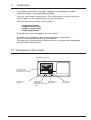
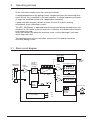
Technical Information
Ampere-hour Meters
AZ 2000 DSZ
ba_az2000_dsz.FH5 0298 - 1 -
Contents
1.
Important
3
2.
lntroduction
4
2.1
Description of the controls
4
3.
Operating principle
5
3.1
Block circuit diagram
5
4.
Instrument descriptions
6
5.
Evaluation of summation currents with the potential Isolation modules
TMD U/U and the AZ 2000 DSZ
7
5.1
Functional circuit diagram
7
6.
Description electrical dosing systems
8
6.1
Introduction
8
6.2
Electronic dosing system DSZ
9
6.2.1
Functional circuit diagram of the DSZ to dosing systems
9
7.
Ampere-hour meter AZ 2000 DSZ with magnetic-dosing pump
10
7.1
Functional circuit diagram AZ 2000 DSZ with gamma/4-b
10
8.
Technical data
11
9.
Connection diagrams
12
9.1
Connection AZ 2000 DSZ
12
9.2
Connection isolating modules to AZ 2000 DSZ
13
9.3
Connection DSZ to magnetic-dosing pump gamma/4-b
14
10.
Setting instructions
15
10.1
Preparation of the unit
15
10.2
Setting procedure
15
10.3
Setting tables Ampere-hour meter/Ampere-minute meter
16
10.3.1 Ampere-hour meter AZ 2000 DSZ
16
10.3.2 Ampere-minute meter AZ 2000 DSZ
17
ba_az2000_dsz.FH5 0298 - 2 -
1.
Important
Before starting up the equipment the Operating lnstructions should be read carefully.
Special attention must be paid to all notes referring to dangerous hazards in the
use of the equipment.
This equipment is constructed and tested to Protection Class II according to
DIN 57 411 Part 1, VDE 0411 Part 1. Protective measures for electronic measuring
equipment. lt has left the factory in perfect condition with regard to all safety aspects.
Any repair or any replacement of components must only be carried out by a special ist
fully familiar with the hazards involved and with the contents VDE Regulations 0411.
ba_az2000_dsz.FH5 0298 - 3 -
2.
Introduction.
In the Ampere-hour Meters Az 2000 - 4000 we have developed a modern
equipment design for electroplating technology.
The units are of modular construction. They are therefore very easy to service
and all models can be supplied from stock on short delivey.
These measuring instruments can be used as
- ampere-hour meter
- ampere-minute meter
- ampere-second meter
- metal weigtit meter
The calibration can be changed by the user himseif.
All models are available with built-in electronic dosing systemwhich
offers current-related dosing of chemical additives.
The automatic uniform dosing of additives ensures a constant bath composition
(and therefore uniform quality).
2.1 Descripfion of the controls
Summation counter
1
Insert the reset
key here to reset
the summation counter
AZ 2000 DSZ
Ah / Amin- ZÄHLER
Netz
Mains lamp
(green)
3
0
sec
100
Ah/Amin
MB
LED signal
Signal lamp for
lights above or
dosing puls
below the measuring
range
Pre-setting of
dosing time
ba_az2000_dsz.FH5 0298 - 4 -
3.
Operating principle
All the instrument models have the same basic design.
A voltage proportional to the plating current is produced across the measuring resistance (shunt); this is amplified in the input amplifier. A voltage/frequency converter
changes the amplified voltage into a proportional trequency.
A programmable frequency divider ensures that the Ah or Amin reading
corresponds to the summation current.
The LED ,,MB Monitor" is operated when the measured voltage exceeds a pre-setmaximum or falls below a pre-set minimum. lt indicates that reliable measurement
is no longer ensured.
When the voltage falls below the minimum value, a pulse blockage 5 activated
which stops the count.
The counting pulses of the summation counter are also used to control the
electronic dosing system.
3.1
Block circuit diagram
Optokoppler
Measured voltage
Measuring
resistance
Input
amplifier
60mV
Magnetpump
Precision
voltage
frequency/
converter
U
10kHz
Pre-setting counter
Driver
n
88888
88888
l
f
Frequency divider
3 - 9999
Driver
Summation counter
88888
Pulse
block
range
monitor
MB
Imp/100Ah-Amin
88
Power supply
+12V
+5V
Elektronic
dosing
system
Dosing
pump
-5V
ba_az2000_dsz.FH5 0298 - 5 -
4.
Instrument descriptions
1
AZ 2000 DSZ
Ah / Amin- ZÄHLER
Netz
3
0
sec
100
Ah/Amin
MB
AZ 2000 DSZ
This instrument operates as a summation
counter witb a 6-digit electromechanical
counter. The reading is reset with a key.
This prevents unintentional changes in the
counter reading.
With a difterent case size (W x H 144x72) it
is possible to incorporate an electronic
dosing system DSZ in this unit.
Connection to the gamma/4-b magneticdosing pump is possible with the standard
optocoupler output.
Range monitor -MBThe AZ 2000 DSZ is equipped with a signal
monitoring device. If the input voltage is
smaller than approx. 1mV and arger than
approx. 170 mv (nominal signal
voltage = 60 mV) this is indicated
by the LED marked MB. Under these
conditions reliable measurement is no
longer assured.
ba_az2000_dsz.FH5 0298 - 6 -
5.
Evaluation of summation currents with the potential
Isolation modules TMD U/U and the AZ 2000 DSZ
When several plating rectifiers in a plant are operated with a common electrolyte,manual or
automatic dosing of electrolyte additives involves the total summation current.
This 5 achieved by connecting to each plating rectifier a TMD U/U and evaluating the plating
current through the so-called shunt voltage.
The outputs of the potential isolation modules TMD U/U are connected in series (summated)
and passed to be AZ 2000 DSZ as the total summation current.
The measuring voltage of the AZ 2000 DSZ is corresponding directely to the plating current.
(see
the drawing)
The AZ 2000 DSZ is used for indicating the total summation current, and for controlling the
dosing equipment.
5.1 Functional circuit diagram
The output of the TMD is corresponding to the shunt current, eg.500A = 500mV.
So the relation is 1:1. (1A = 1mV)
Rectifier
A
V
A
V
A
V
A
V
Potential isolator TMD UU
+
0-60mV
0-600mV
+
+
+
AZ 2000 DSZ
+
+
0-60mV
0-600mV
1
800A
800A
Shunt
resistor
+
0-60mV
0-600mV
AZ 2000 DSZ
Ah / Amin- ZÄHLER
Netz
800A
3
0
sec
100
Ah/Amin
MB
2400mV = 3200A
+
0-60mV
0-600mV
800A
A free inlet must be arranged
in order to prevent the bath
alralning back into the
dosing container in case
of a fault
Dosing
pump
Electrolyte
Filter
Plating bath
Dosing container
Circulating
pump
ba_az2000_dsz.FH5 0298 - 7 -
6.
Description electrical dosing systems
6.1 Introduction
During electrochemical processes in electroplating beths the electrical current
causes metals to be deposited.
The quantity of metal deposited depends on the magnitude of the electrical
current, the plating time, and the electrochemical equivalent of the metal.
In order to ensure that the plating bath has a uniform quality it is necessary to
replase the deposited metal and to feed in other chemical additives.
It provides for accurate, current-related dosing of the necessary substances.
We have developed the following dosing system for the different applications:
-DSZ:
selection of the dosing time in sec/min
per 10/100/1000 Ah/Amin
-AZ/gamma/4-b:
Setting the Ah/Amin after which a control pulse output is
produced. This is selected directly on the programmble
gamma/4-b magnetic dosing pump.
The operation of the electronic dosing systems is described in detail in
Sections 6.2-6.5.
The basic arrangement of a dosing system is illustrated in the functuional
circuit diagram below.
Rectifier
A
Ampere-hour meter
AZ 2000 DSZ
V
1
AZ 2000 DSZ
Ah / Amin- ZÄHLER
Netz
3
0
sec
100
Ah/Amin
MB
+
Shunt
Tank
ba_az2000_dsz.FH5 0298 - 8 -
6.2 Electronic dosing system DSZ
The dosing System DSZ causes a timer to be started up at intervais of 10 / 100 or 1000 Ah/Amin.
The on-time of the timer can be adjusted between 1 and 99 seconds on the front panel of the
AZ. An option is an build in adjustment range.
Example:
Selected on-time:
30 sech 100 Ah/Amin.
Operating mode:
every 100 Ah/Amin a dosing pump or a solenoid valve is energised
or opened for a duration of 30 seconds.
The dosing quantity depends on the output of the pump or on the flow rate at the solenoid valve.
The output of the dosing system DSZ consists of a volt-free switching contact (8 A /250 V)
which controls the supply voltage of the dosing pump or solenoid valve.
6.2.1Functional circuit diagram DSZ on dosing equipment
Rectifier
A
Ampere-hour meter
AZ 2000 DSZ
V
L N PE
1
AZ 2000 DSZ
Ah / Amin- ZÄHLER
Netz
3
0
sec
100
Ah/Amin
MB
+
Shunt
Magnet-dosing pump
Tank
ba_az2000_dsz.FH5 0298 - 9 -
7.
Ampere-hour meter AZ 2000 DSZ with magnetic dosing pump
Operating an ampere-hour meter in conjunction with the programmable magnetic
dosing pump gamma/4-b produces dosing in accordance with a pre-selected
number of Ah/Amin.
On each step of the totalising counter or presetting counter the ampere-hour counter
outputs a pulse through its optocoupler output to the magnetic dosing pump gamma/4-b.
The gamma /4-b pump must now be set to produce a certain number of dosing strokes
for each step of the totalising or presetting counter.
In the conversion of AZ pulses to dosing strokes there is a choice between a step-up
and a step-down ratio of the control pulses.
Step-up:
a single totalising or presetting counter pulse of the AZ generates n
dosing strokes.
Step-down: n totalising or presefling counter pulse of the AZ generate a single
dosing stroke.
7.1 Functional circuit diagramm AZ 2000 DSZ with gamma/4-b
Magnet-dosing pump
Rectifier
A
Ampere-hour meter
AZ 2000 DSZ
V
1
AZ 2000 DSZ
Ah / Amin- ZÄHLER
Netz
3
0
sec
100
Ah/Amin
MB
+
Shunt
Dosing
Container
Tank
ba_az2000_dsz.FH5 0298 - 10 -
8.
Technical data
Countermodel
Summation counter
6-digit, mechanical
AZ 2000
X
AZ 2000 DSZ
AZ 4000
AZ4000 DSZ
X
X
X
X
X
Pre-sefling counter
6-digit, electronic
Floating Optocoupler output to
control the gammal4-b
pump
X
Floating relay
output to control the
gamma/4-b pump
X
X
X
Relay output 8 AI250 V
50160 Hz
Measurement
accuracy
0,1%
Ambient temperature
Supply
0,1%
X
X
0,1%
0,1%
0-50°C
230V 50 Hz/60 Hz (Other voltages to special order)
Protection
IP 44
Weight
550 g
1000 g
1100 g
1150 g
Panel cut-out (mm)
90,5x43
137x66
137x66
137x66
Dimensions (mm)
WxHxD
48x96x180
72x144x180 72x144x180 72x144x180
Note: If a contactor operated by the relay output does not drop out when the relay
contact is open, the RC interference suppressor next to the relay output has
to be removed. In order to avoid severe wear on the relay contacts the RC
interference suppressor is then connected in parallel with the inductive load.
ba_az2000_dsz.FH5 0298 - 11 -
9.
Connection diagrams
Circuit board
9.1 Connection AZ 2000 DSZ
C E
Current-input for
internal shunt
(max. 12A optional)
Input for external resetting of the
electronic presetting counters
C E
(Backview)
Data-output
optokoppler 1
Relay-output for
pre-setting counter
use shielded cable
AZ 2000 DSZ
Power (230V-AC/50Hz)
PE
L
N
Rectifler
A
V
+
Shunt
Amperehourmeter
Data-output
optokoppler 2
ba_az2000_dsz.FH5 0298 - 12 -
9.2 Connection isolating modules to AZ 2000 DSZ
NEUKUM elektronik GmbH
TMD U / U
Betriebsspannung: 230 V AC
6
- Ausgang
230 V AC
1
5
+ Ausgang
230 V AC
2
4
+ Eingang
Eingang -
3
Shunt n
+
from rectifler
Potential-disconnect module
TMD U/U
NEUKUM elektronik GmbH
6
- Ausgang
230 V AC
1
5
+ Ausgang
230 V AC
2
4
+ Eingang
Eingang -
3
Shunt 2
Shield
TMD U / U
Betriebsspannung: 230 V AC
+
from rectifler
NEUKUM elektronik GmbH
AZ 2000 DSZ
TMD U / U
Betriebsspannung: 230 V AC
6
- Ausgang
230 V AC
1
5
+ Ausgang
230 V AC
2
4
+ Eingang
Eingang -
3
Shunt 1
Shuntconnection
-
Shield
+
+
Innenconduct
from rectifler
Innenconduct
L
N
PE
Power
ba_az2000_dsz.FH5 0298 - 13 -
L
N
PE
Rectifler
A
Shunt
V
+
AZ 2000 DSZ
Ampere-hour-meter (Backview)
Magnet-Dosing pump
9.3 Connection DSZ to magnetic dosing pump gamma/4-b
ba_az2000_dsz.FH5 0298 - 14 -
10. Setting instructions for the counters Series AZ....
The following notes and setting tables apply to the calibration of the AZ and to
changing the indication accuracy (resolution).
10.1 Preparation of the unit
IMPORTANT:
Before opening the unit, check that it is not live!
Otherwise the operation is extremely hazardous!!
The circuit board must onty be touched at the edges!
Make sure that you do not carry any electrostatic charges, otherwise the sensitive MOS
components may be destroyed. Discharge any static charge by touching a metai object at
ground potential, such as water pipe, earth connection, or a large metal object such as a
bench.
AZ 2000 DSZ
1.
Open the back paneI and
carefully remove the circuit
board.
2.
Make the adjustments according
to the table. The location of
the controls is shown in the
diagrams below.
3.
After the adjustments have
been made, slide the circuit
board back into the housing.
Take care with the front and
the controls. Replace the
back panel.
10.2 Setting procedure
The rotary switches SA, SB, SC, SD are used to set the division ratio. The settings
depend on the shunt resistance used, and also on the required measuring unit
(Ampere-hour, Ampere-minute).
The equipment is set at the factory according to your order details.
lt can however readily be changed with reference to the tables.
(Please use a small watchmaker´s screwdriver!)
The pre-setting counter and summation counter each have in addition a set of 3
switches in order to determine the number of places after the decimal point. The
tables show the values for the various shunt resistances.
Please note that the counters may have to be provided with a "decimal point" (label).
Appropriate symbols are placed on the internal face of the housing back.
ba_az2000_dsz.FH5 0298 - 15 -
10.3
Setting tables Ampere-hour meter/Ampere-minute meter
10.3.1
Ampere-hour meter AZ 2000 DSZ
Pre-setting
switches
Shunt
ABCD
40 A
50 A
60 A
80 A
100 A
150 A
200 A
250 A
300 A
400 A
500 A
600 A
800 A
1000 A
1200 A
1500 A
2000 A
2500 A
3000 A
4000 A
5000 A
6000 A
8000 A
10000 A
9
7
6
4
3
2
1
1
1
0
0
0
0
0
0
0
0
0
0
0
0
0
0
0
0
2
0
5
6
4
8
4
2
9
7
6
4
3
3
2
1
1
1
0
0
0
0
0
0
0
0
0
0
0
0
4
0
0
2
0
5
6
0
4
8
4
2
9
7
6
4
3
0
0
0
0
0
0
0
0
0
0
0
0
0
0
0
0
0
4
0
0
2
0
5
6
Summation counter
reading / hour
Pre-setting counter
reading / hour
S1
S2
S3
S4
S5
S6
0040,00
0050,00
0060,00
0080,00
0100,00
0150,00
0200,00
0250,00
0300,00
-
00040,0
00050,0
00060,0
00080,0
00100,0
00150,0
00200,0
00250,0
00300,0
00400,0
00500,0
00600,0
00800,0
01000,0
01200,0
01500,0
02000,0
02500,0
03000,0
-
000040
000050
000060
000080
000100
000150
000200
000250
000300
000400
000500
000600
000800
001000
001200
001500
002000
002500
003000
004000
005000
006000
008000
010000
040,00
050,00
060,00
080,00
100,00
150,00
200,00
250,00
300,00
400,00
500,00
600,00
800,00
-
0040,0
0050,0
0060,0
0080,0
0100,0
0150,0
0200,0
0250,0
0300,0
0400,0
0500,0
0600,0
0800,0
1000,0
1200,0
1500,0
2000,0
2500,0
3000,0
4000,0
5000,0
6000,0
8000,0
-
00040
00050
00060
00080
00100
00150
00200
00250
00300
00400
00500
00600
00800
01000
01200
01500
02000
02500
03000
04000
05000
06000
08000
10000
(only 1 .... may
be connected)
SA SB SC SD
Pre-selecting switch
S4 S5 S6 S1 S2 S3
IC
Connection block
Board
Trafo
Circuit board for electronic dosing
LED yellow
Circuit board for dosing preparation
LED green
ba_az2000_dsz.FH5 0298 - 16 -
10.3.2
Ampere-minute meter AZ 2000 DSZ
Pre-setting
switches
Summation counter
reading / minute
Shunt A B C D
1A
2A
4A
5A
6A
10 A
15 A
20 A
25 A
40 A
50 A
60 A
100 A
150 A
200 A
250 A
300 A
400 A
6
3
1
1
1
0
0
0
0
0
0
0
0
0
0
0
0
0
00
00
50
20
00
60
40
30
24
15
12
10
06
04
03
02
02
01
0
0
0
0
0
0
0
0
0
0
0
0
0
0
0
4
0
5
S1
S2
0001,00
0002,00
0004,00
0005,00
0006,00
-
00001,0
00002,0
00004,0
00005,0
00006,0
00010,0
00015,0
00020,0
00025,0
00040,0
00050,0
00060,0
-
Pre-setting counter
reading / minute
S3
S4
000001
000002
000004
000005
000006
000010
000015
000020
000025
000040
000050
000060
000100
000150
000200
000250
000300
000400
001,00
002,00
004,00
005,00
006,00
010,00
015,00
020,00
025,00
040,00
050,00
060,00
100,00
150,00
200,00
250,00
300,00
400,00
S5
S6
0001,0
0002,0
0004,0
0005,0
0006,0
0010,0
0015,0
0020,0
0025,0
0040,0
0050,0
0060,0
0100,0
0150,0
0200,0
0250,0
0300,0
0400,0
00001
00002
00004
00005
00006
00010
00015
00020
00025
00040
00050
00060
00100
00150
00200
00250
00300
00400
(only 1 .... may
be connected)
S4 S5 S6 S1 S2 S3
IC
Connection block
Board
SA SB SC SD
Pre-selecting switch
Trafo
Circuit board for electronic dosing
LED yellow
Circuit board for dosing preparation
LED green
ba_az2000_dsz.FH5 0298 - 17 -