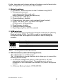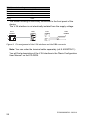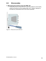
1
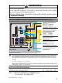
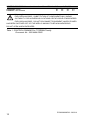
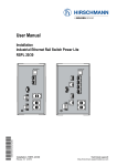
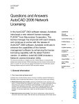
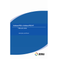
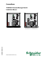
ConneXium TCSESM-E Extended Managed Switch Installation Manual ConneXium Switch U: 24 / 48 V DC ConneXium Switch U: 24 / 48 VDC P1 P1 R1 P - R1 P - R2 RM + R2 RM + Fault Stand by z USB R1 z Fault Stand by z USB 1 1 2 U: 24 / 48 VDC IP-ADDRESS IP-ADDRESS U: 24 / 48 V DC P2 + P2 + 3 4 R2 z 7 8 TCSESM083F23F1 / TCSESM083F23F1C www.schneider-electric.com 2 MAC-Address 5 6 UNINTENDED OPERATION Do not change cable positions if DHCP Option 82 is enabled. Check user manual before servicing. MAC-Address 3 4 UNINTENDED OPERATION Do not change cable positions if DHCP Option 82 is enabled. Check user manual before servicing. z V.24 V.24 EIO0000000529.02 R1 5 6 R2 z 7 8 TCSESM063F2CU1 / TCSESM063F2CU1C TCSESM063F2CS1 / TCSESM063F2CS1C Contents About this Manual 3 Key 5 Safety instructions 6 1 Device description 13 1.1 General device description 13 1.2 Device versions 14 2 Assembly and start-up 16 2.1 Safety instructions 16 2.2 Installing the device 2.2.1 Overview of installation 2.2.2 Unpacking and checking 2.2.3 Insert data in label area 2.2.4 Connecting the terminal blocks for supply voltage and signal contact 2.2.5 Installing the device and grounding 2.2.6 Installing the terminal blocks; start-up procedure 2.2.7 Connecting the data lines 16 16 17 17 2.3 Display elements 23 2.4 Basic set-up 26 2.5 Disassembly 29 3 Technical data 30 2 18 20 21 21 EIO0000000529 - 02/2011 About this Manual Validity Note The data and illustrations found in this book are not binding. We reserve the right to modify our products in line with our policy of continuous product development. The information in this document is subject to change without notice and should not be construed as a commitment by Schneider Electric. Product Related Information Schneider Electric assumes no responsibility for any errors that may appear in this document. If you have any suggestions for improvements or amendments or have found errors in this publication, please notify us. No part of this document may be reproduced in any form or by any means, electronic or mechanical, including photocopying, without express written permission of Schneider Electric. All pertinent state, regional, and local safety regulations must be observed when installing and using this product. For reasons of safety and to ensure compliance with documented system data, only the manufacturer should perform repairs to components. When devices are used for applications with technical safety requirements, please follow the relevant instructions. Failure to use Schneider Electric software or approved software with our hardware products may result in improper operating results. Failure to observe this product related warning can result in injury or equipment damage. User Comments We welcome your comments about this document. You can reach us by e-mail at [email protected] EIO0000000529 - 02/2011 3 Related Documents Title ConneXium TCSESM, TCSESM-E Managed Switch Redundancy Configuration User Manual ConneXium TCSESM, TCSESM-E Managed Switch Basic Configuration User Manual ConneXium TCSESM, TCSESM-E Managed Switch Command Line Interface Reference Manual ConneXium TCSESM, TCSESM-E Managed Switch Web-based Interface Reference Manual ConneXium TCSESM Managed Switch Installation Manual ConneXium TCSESM-E Extended Managed Switch Installation Manual Reference Number 31007126 31007122 31007130 EIO0000000482 31007118 EIO0000000529 Note: The Glossary is located in the Reference Manual “Command Line Interface”. The “Web-based Interface” reference manual contains detailed information on using the Web interface to operate the individual functions of the device. The “Command Line Interface” Reference Manual contains detailed information on using the Command Line Interface to operate the individual functions of the device. The “Installation” user manual contains a device description, safety instructions, a description of the display, and the other information that you need to install the device. The “Basic Configuration” user manual contains the information you need to start operating the device. It takes you step by step from the first startup operation through to the basic settings for operation in your environment. The “Redundancy Configuration” user manual contains the information you need to select a suitable redundancy procedure and configure that procedure. 4 EIO0000000529 - 02/2011 Key The symbols used in this manual have the following meanings: X Listing Work step Subheading EIO0000000529 - 02/2011 5 Safety instructions Important Information Notice: Read these instructions carefully, and look at the equipment to become familiar with the device before trying to install, operate, or maintain it. The following special messages may appear throughout this documentation or on the equipment to warn of potential hazards or to call attention to information that clarifies or simplifies a procedure. The addition of this symbol to a Danger or Warning safety label indicates that an electrical hazard exists, which will result in personal injury if the instructions are not followed. This is the safety alert symbol. It is used to alert you to potential personal injury hazards. Obey all safety messages that follow this symbol to avoid possible injury or death. DANGER DANGER indicates an imminently hazardous situation which, if not avoided, will result in death or serious injury. WARNING WARNING indicates a potentially hazardous situation which, if not avoided, can result in death or serious injury. CAUTION CAUTION indicates a potentially hazardous situation which, if not avoided, can result in minor or moderate injury. PLEASE NOTE: Electrical equipment should be installed, operated, serviced, and maintained only by qualified personnel. No responsibility is assumed by Schneider Electric for any consequences arising out of the use of this material. © 2010 Schneider Electric. All Rights Reserved. Usage The device may only be employed for the purposes described in the catalog, technical description, and manuals. 6 EIO0000000529 - 02/2011 Supply voltage The device does not contain any user-serviceable components. Internal fuses only trigger if there is a detected error in the device. Apply supply voltage to the device if terminal blocks are wired and installed correctly as described in chapter “Connecting the terminal blocks for supply voltage and signal contact” on page 18. Connect the protective conductor with the ground screw before you set up the other connections. When removing the connections, you remove the protective conductor last. Make sure that the cross-section of the protective conductor cable is the same size as or bigger than the cross-section of the voltage supply cables. Only use connection cables that are permitted for the specified temperature range. WARNING LOSS OF COMMUNICATION If the neutral conductor or the negative terminal of the supply voltage is not grounded, install a suitable input fuse. Use a slow-blow fuse with a nominal rating of 6.3 A for the voltage supply input. Failure to follow these instructions can result in death, serious injury, or equipment damage. Use a cable cross-section of at least 1.0 mm² (for North America, AWG 16) for the current conductor at the voltage input. Relevant for North America: Only use 75 °C copper wire. Shielding ground The shielding ground of the connectable twisted pair lines is connected to the front panel as a conductor. Housing DANGER HAZARD OF ELECTRIC SHOCK Never insert sharp objects (small screwdrivers, wires, etc.) into the inside of the product. Failure to follow these instructions will result in death, serious injury, or equipment damage. EIO0000000529 - 02/2011 7 CAUTION EQUIPMENT OVERHEATING When installing the device, make sure any ventilation slots remain free. Maintain a clearance of at least 10 cm (3.94 in). Failure to follow these instructions can result in injury or equipment damage. Only technicians authorized by the manufacturer are permitted to open the housing. The device is grounded via the separate ground screw. It is located on the bottom left of the front panel. Make sure that the electrical installation meets local or nationally applicable safety regulations. The ventilation slots must not be covered to promote free air circulation. The clearance to the ventilation slots of the housing must be at least 10 cm (3.94 in). The device must be installed in the vertical position. If installed in a living area or office environment, the device must be operated exclusively in switch cabinets with fire protection characteristics according to EN 60950-1. Environment The device may only be operated at the specified surrounding air temperature (temperature of the surrounding air at a distance of up to 5 cm (1.97 in) from the device) and relative air humidity specified in the technical data. Install the device in a location where the climatic threshold values specified in the technical data will be observed. Use the device only in an environment within the pollution degree specified in the technical data. General safety instructions Electricity is used to operate this equipment. Comply with every detail of the safety requirements specified in the operating instructions regarding the voltages to apply (see page 7). Only qualified personnel should work on this device or in its vicinity. These personnel must be thoroughly familiar with all the hazard messages and maintenance procedures in accordance with this operating manual. The proper and safe operation of this device depends on proper handling during transport, proper storage and assembly, and conscientious operation and maintenance procedures. 8 EIO0000000529 - 02/2011 Never start operation with damaged components. Any work that may be required on the electrical installation may only be carried out by personnel trained for this purpose. Note: LED or LASER components in compliance with IEC 60825-1 (2001): CLASS 1 LASER PRODUCT CLASS 1 LED PRODUCT Light is emitted from the optical connections or from the ends of the connected optical fibers that are connected to the optical connections. LIGHT EMITTING DIODE CLASS 2 M, wave length 650 nm, power <2 mW in accordance with DIN EN 60825-1:2003-10. LIGHT EMITTING DIODE CLASS 1 - CLASS 1 LED PRODUCT WARNING EYE DAMAGE DUE TO LASER LIGHT Do not look into the beam or view the beam directly with optical instruments (magnifying glasses, microscope) at a distance of less than 100 mm (3.94 in). Failure to follow these instructions can result in death, serious injury, or equipment damage. National and international safety regulations Make sure that the electrical installation meets local or nationally applicable safety regulations. CE marking The devices comply with the regulations contained in the following European directive(s): 2004/108/EG Directive of the European Parliament and the council for standardizing the regulations of member states with regard to electromagnetic compatibility. In accordance with the above-named EU directive(s), the EU conformity declaration will be at the disposal of the relevant authorities at the following address: Schneider Electric 35 rue Joseph Monier CS30323 92506 Rueil-Malmaison-France EIO0000000529 - 02/2011 9 The product can be used in the industrial sector. X Interference immunity: EN 61000-6-2:2005 X Emitted interference: EN 55022:2006 + A1:2007 Class A FCC note: This device complies with part 15 of FCC rules. Operation is subject to the following two conditions : (1) This device may not cause harmful interference; (2) this device must accept any interference received, including interference that may cause undesired operation. Appropriate testing has established that this device fulfills the requirements of a class A digital device in line with part 15 of the FCC regulations. These requirements are designed to provide sufficient protection against interference when the device is being used in a business environment. The device creates and uses high frequencies and can radiate same, and if it is not installed and used in accordance with this operating manual, it can cause radio transmission interference. The use of this device in a living area can also cause interference, and in this case the user is obliged to cover the costs of removing the interference. Instructions for Use in Hazardous Locations SUITABLE FOR USE IN CLASS I, DIVISION 2, GROUPS A, B, C AND D HAZARDOUS LOCATIONS, OR NONHAZARDOUS LOCATIONS ONLY. WARNING EXPLOSION HAZARD Substitution of any components may impair suitability for CLASS I, DIVISION 2. Failure to follow these instructions can result in death, serious injury, or equipment damage. WARNING EXPLOSION HAZARD Do not disconnect equipment unless power has been switched off or the area is known to be non-hazardous. Failure to follow these instructions can result in death, serious injury, or equipment damage. 10 EIO0000000529 - 02/2011 WARNING EXPLOSION HAZARD Do not use USB connector, or connect or disconnect devices from it unless the area is known to be non-hazardous. Failure to follow these instructions can result in death, serious injury, or equipment damage. CONTROL DRAWING: Hazardous Locations Class I Division 2 Groups A, B ,C ,D Power supply (Redundant) P1 Type "K": 110-230VAC or 60-250VDC ConneXium Switch P2 Type "C": 24-48VDC (protective earthing conductors Type "K" only) Fault Fault UNINTENDED OPERATION Do not change cable positions if DHCP Option 82 is enabled. Check user manual before servicing. 1 Data communication Ethernet Ports 5 6 7 8 EAM Memory Back-up Adapter. For maintenance only See Installation Instructions. 9 10 IP54 enclosure HAZARDOUS LOCATION 1 Fault contacts. Equipment with nonincendive field wiring parameters: V<30V I<90mA Li<0,5µH Ci<20pF Non Hazardous Location V.24 Interface (External management) Notes: The nonincendive field wiring circuit concept allows interconnection of nonincendive field wiring apparatus and associated nonincendive field wiring apparatus using any of the wiring methods permitted for unclassified locations when certain parametric conditions are met. Ca >= Ci + Ccable ; La >= Li + Lcable Nonincendive field wiring circuits must be wired in accordance with the National Electrical Code (NEC), NFPA 70 , article 501. Nonincendive Field Wiring Parameters: Entity Parameters for Class I Division 2 Groups A,B,C,D Vmax [V] Imax [mA] Ci [pF] Li [µH] Table 1: CONTROL DRAWING for TCSESM-E family Document No.: 000144941DNR EIO0000000529 - 02/2011 11 CONTROL DRAWING: Hazardous Locations Class I Division 2 Groups A, B ,C ,D Connector: 2 pole 30 90 20 0.5 Contacts: Fault contacts 30 90 20 0.5 Warnung! EXPLOSION HAZARD - SUBSTITUTION OF COMPONENTS MAY IMPAIR SUITABILITY FOR HAZARDOUS LOCATIONS OR EXPLOSIVE ATMOSPHERES. EXPLOSION HAZARD - DO NOT DISCONNECT EQUIPMENT UNLESS POWER HAS BEEN SWITCHED OFF OR THE AREA IS KNOWN TO BE NON-HAZARDOUS. DO NOT OPEN WHEN ENERGIZED. Table 1: CONTROL DRAWING for TCSESM-E family Document No.: 000144941DNR 12 EIO0000000529 - 02/2011 1 1.1 Device description General device description The TCSESM-E devices are designed for the special requirements of industrial automation. They meet the relevant industry standards, provide very high operational reliability, even under extreme conditions, and also long-term reliability and flexibility. The devices allow you to set up switched industrial ETHERNET networks that conform to the IEEE 802.3 and 802.3u standards using copper wires or optical fibers in a line or ring structure. The devices work without a fan. The voltage is supplied redundantly. Mount the devices by X simply snapping them onto a DIN rail Depending on the device variant, you can choose various media to connect terminal devices and other infrastructure components: X twisted pair cable X multimode F/O X singlemode F/O The twisted pair ports support: X Autocrossing X Autonegotiation X Autopolarity There are a number of convenient options for managing the device. Administer your devices via: X a Web browser X Telnet X a V.24 interface (locally on the Switch) Product configuration data can be provided by: X diagnosis displays X displaying the operating parameters X a label area for the IP address The devices provide you with a large range of functions: X Redundancy functions X Rapid Spanning Tree Protocol (RSTP) X HIPER-Ring X Fast HIPER-Ring EIO0000000529 - 02/2011 13 X X X X X X X X X X X X X X X X Media Redundancy Protocol (MRP) X Redundant coupling X Redundant power supply Security X Protection from unauthorized access X Blocking of unauthorized messages (MAC or IP based) Synchronized system time in the network Network load control Network filter Operation diagnosis Diagnostics (hardware self-testing) Reset Priority VLAN Topology Discovery Web-based Interface Command Line Interface CLI SNMP 802.1x port authentication Real Time Clock 1.2 Device versions Part number 8 port version Accessories 14 Part number TCSESM083F23F1 TCSESM063F2CU1 Description 8 x 10/100 TX managed 6 x 10/100 TX managed 2 x 100 FX-MM managed TCSESM063F2CS1 6 x 10/100 TX managed 2 x 100 FX-SM managed TCSESM083F23F1C 8 x 10/100 TX managed, Conformal Coating TCSESM063F2CU1C 6 x 10/100 TX managed 2 x 100 FX-MM managed, Conformal Coating TCSESM063F2CS1C 6 x 10/100 TX managed 2 x 100 FX-SM managed, Conformal Coating TCSEAM0100 Adapter Memory Back-up Adapter 490NTRJ11 cable Terminal cable EIO0000000529 - 02/2011 ConneXium Switch U: 24 / 48 V DC 1 ConneXium Switch P1 - RM + Stand by z USB R1 z V.24 12 3 10 5 12 7 11 7 8 8 TCSESM083F23F1 / TCSESM083F23F1C UNINTENDED OPERATION Do not change cable positions if DHCP Option 82 is enabled. Check user manual before servicing. z 9 - RM + Fault Stand by z USB R1 1 6 3 4 R2 P 2 3 z 4 V.24 - 5 6 R1 R2 4 P2 + MAC-Address 11 UNINTENDED OPERATION Do not change cable positions if DHCP Option 82 is enabled. Check user manual before servicing. IP-ADDRESS U: 24 / 48 V DC 1 2 2 5 U: 24 / 48 VDC IP-ADDRESS P P2 - 6 + 3 4 2 MAC-Address R1 R2 Fault 1 U: 24 / 48 VDC P1 5 6 R2 z 7 7 8 10 8 9 TCSESM063F2CU1 / TCSESM063F2CU1C TCSESM063F2CS1 / TCSESM063F2CS1C Figure 1: The figure shows the versions of the TCSESM-E. 1 – voltage range 1 (nominal voltage 24 V DC to 48 V DC) 2 – LED display elements 3 – USB interface 4 – signal contact 1 5 – V.24 connection for external management 6 – voltage range 2 (nominal voltage 24 V DC to 48 V DC) 7 – signal contact 2 8 – protective ground (PE) 9 – ports in compliance with 10/100BASE-T(X) (RJ45 connections) – LAN only 10 – port 1 + port 2: TCSESM063F2CU1 / TCSESM063F2CU1C: Multimode FX, DSC, 100 Mbit/s – LAN only TCSESM063F2CS1 / TCSESM063F2CS1C: Singlemode FX, DSC, 100 Mbit/s – LAN only 11 – MAC address field 12 – IP address field EIO0000000529 - 02/2011 15 2 2.1 Assembly and start-up Safety instructions Staff qualification requirements Only appropriately qualified staff should work on or near this equipment. Such staff must be thoroughly acquainted with all the hazard messages and maintenance measures contained in these operating instructions. The proper and safe operation of this equipment assumes proper transport, appropriate storage and assembly, and careful operation and maintenance. Qualified staff are persons familiar with setting up, assembling, installation, starting up, and operating this product, and who have appropriate qualifications to cover their activities, such as: X knowledge of how to switch circuits and equipment/systems on and off, ground them, and identify them in accordance with current safety standards X training or instruction in accordance with current safety standards of using and maintaining appropriate safety equipment X first aid training Recycling note After usage, this product must be disposed of properly as electronic waste, in accordance with the current disposal regulations of your county, state and country. 2.2 Installing the device 2.2.1 Overview of installation Two or more devices configured with the same IP address can cause unpredictable operation of your network. 16 EIO0000000529 - 02/2011 WARNING UNINTENDED EQUIPMENT OPERATION Establish and maintain a process for assigning unique IP addresses to all devices on the network. Failure to follow these instructions can result in death, serious injury, or equipment damage. WARNING UNINTENDED OPERATION Do not change cable positions if DHCP Option 82 is enabled. Check the Basic Configuration user manual before servicing (refer to DHCP OPTION 82 topic). Failure to follow these instructions can result in death, serious injury, or equipment damage. On delivery, the device is ready for operation. The following steps should be performed to install and configure a switch: X Unpacking and checking X Insert data in label area X Connect the terminal block for voltage supply and signal contact and connect the supply voltage X Install the basic module on the DIN rail, grounding X Install the terminal block, start-up procedure X Connecting the data lines 2.2.2 Unpacking and checking Check that the contents of the package are complete (see page 32 “Scope of delivery”). Check the individual parts for transport damage. 2.2.3 Insert data in label area The information field for the IP address on the front of the device helps you to structure your network installation clearly. EIO0000000529 - 02/2011 17 ConneXium Switch U: 24 / 48 V DC P1 R1 P - R2 RM + Fault Stand by z USB R1 z V.24 1 P2 + 3 4 MAC-Address 2 UNINTENDED OPERATION Do not change cable positions if DHCP Option 82 is enabled. Check user manual before servicing. IP-ADDRESS U: 24 / 48 V DC 1 2 5 6 R2 z 7 8 Figure 2: Label area for IP address of device 1 – IP address of device (label area) 2 – MAC address of device (label) 2.2.4 Connecting the terminal blocks for supply voltage and signal contact The supply voltage is connected via a 2-pin terminal block with screw locking. The signal contacts are connected via a 2-pin terminal block with screw locking. Supply voltage DANGER HAZARD OF ELECTRIC SHOCK OR BURN When the module is operated with direct plug-in power units, use only: – SELV supply units that comply with IEC 60950/EN 60950 and – (in USA and Canada) Class 2 power units that comply with applicable national or regional electrical codes Connect the ground wire to the PE terminal (where applicable) before you establish any further connections. When you remove connections, disconnect the ground wire last. Failure to follow these instructions will result in death, serious injury, or equipment damage. Redundant power supplies can be used. Both inputs are uncoupled. There is no distributed load. With redundant supply, the power supply unit supplies the device only with the higher output voltage. The supply voltage is electrically isolated from the housing. 18 EIO0000000529 - 02/2011 Note: With non-redundant supply of the main voltage, the device reports a loss of power. You can avert this message by applying the supply voltage via both inputs, or by changing the configuration in the Management. The supply voltage is connected via pin 1 and pin 2. Figure Pin Assignment 1 Minus terminal of the supply voltage 12 Plus terminal of the supply voltage 2 Power supply Nominal voltage DC: 24 - 48 V Voltage range DC: 18 - 60 V (incl. max. tolerances), SELV Connection type: 2-pin terminal block Power failure bridging: > 10 ms for 20.4 V DC Fuse: installed in power supply unit Table 2: Connecting the supply voltage Pull the terminal block off the device. Connect the supply voltage lines. Note: Relevant for North America: The tightening torque for field wiring terminals is max. 4.4 lb in (0,5 Nm). Signal contact Figure 3: Pin assignment of the signal contact You have two signal contacts for each device. X The signal contact (“FAULT”, for pin assignment of terminal block, see fig. 3) monitors the functioning of the device, thus enabling remote diagnostics. You can specify the type of function monitoring in the Management. X You can also use the switch Web page to switch the signal contact manually and thus control external devices. A break in contact is used to report the following conditions via the potential-free signal contact (relay contact, closed circuit): X The detected inoperability of at least one of the two voltage supplies (voltage supply 1 or 2 is below the threshold value). EIO0000000529 - 02/2011 19 X The loss of connection at at least one port. The report of the link status can be masked by the Management for each port. In the delivery state, link status monitoring is deactivated. X The temperature threshold has been exceeded or has not been reached. X The removal of the Memory Backup Adapter. The following condition is also reported in RM mode: X Ring redundancy reserve is available. On delivery, there is no ring redundancy monitoring. Pull the terminal block off the device. Connect the signal lines. 2.2.5 Installing the device and grounding You can mount the device on the DIN rail. Mounting on the DIN rail Figure 4: Mounting on the DIN rail Mount the device on a 35 mm DIN rail in accordance with DIN EN 60175. Attach the upper snap-in guide of the device into the DIN rail and press it down against the DIN rail until it snaps into place. Note: The shielding ground of the industrial connectable twisted pair lines is connected to the lower panel as a conductor. 20 EIO0000000529 - 02/2011 Dimension drawings 120 4.72 145,3 5.72 136.44 5.37 mm inch 6,99 0.28 120,83 4.76 Grounding The device is grounded via the separate ground screw on the front panel of the device. The devices have a protective conductor connection. Connect the protective conductor to the ground screw of the device. Connect the protective conductor before you set up the other connections. When removing the connection, you remove the protective conductor last. Connect both protective conductors if your device is equipped with two power supplies units. 2.2.6 Installing the terminal blocks; start-up procedure Mounting the terminal blocks Mount the terminal blocks for the voltage supply and signal contact on the front of the device using screws. Installation By connecting the voltage supply via the terminal blocks, you start the operation of the device. 2.2.7 Connecting the data lines You can connect terminal devices and other segments at the ports of the device via twisted pair cables or F/O cables. EIO0000000529 - 02/2011 21 Install the data lines according to your requirements. 10/100 Mbit/s twisted pair connection These connections are RJ45 sockets. 10/100 Mbit/s TP ports enable the connection of terminal devices or independent network segments according to the IEEE 802.3 10BASE-T/ 100BASE-TX standard. These ports support: X Autonegotiation (data rate and duplex mode) X Autopolarity X Autocrossing (if autonegotiation is activated) X 100 Mbit/s half-duplex mode, 100 Mbit/s full duplex mode X 10 Mbit/s half-duplex mode, 10 Mbit/s full duplex mode State on delivery: autonegotiation activated. The socket housing is electrically connected to the bottom panel. Figure 8 7 6 5 4 3 2 1 Table 3: Pin 1+2 3+6 4,5,7,8 Function One line pair: receiver path One line pair: sender path Not used Pin assignment of a TP/TX interface in MDI-X mode, RJ45 socket Note: In substation applications, the RJ45 ports are used to connect to additional communication devices such as routers or telecommunication multiplexers that are installed in close proximity to the device (i.e. less than 3 meters / 9.83 ft). It is not recommended to use these ports for connection to field devices across longer distances which could cause a significant increase in the ground potential (Ground Potential Rise GPR, i.e. more than 2500 V). 100 Mbit/s F/O connection These connections are DSC connectors. 100 MBit/s F/O ports enable the connection of terminal devices or independent network segments in compliance with the IEEE 802.3 100BASE-FX standard. These ports support: X Full or half duplex mode State on delivery: full duplex FDX 22 EIO0000000529 - 02/2011 Note: Make sure that the SM ports are only connected with SM ports, and MM ports only with MM ports. Note: LED or LASER components in compliance with IEC 60825-1 (2001): CLASS 1 LASER PRODUCT CLASS 1 LED PRODUCT Light is emitted from the optical connections or from the ends of the connected optical fibers that are connected to the optical connections. LIGHT EMITTING DIODE CLASS 2 M, wave length 650 nm, power <2 mW in accordance with DIN EN 60825-1:2003-10. LIGHT EMITTING DIODE CLASS 1 - CLASS 1 LED PRODUCT WARNING EYE DAMAGE DUE TO LASER LIGHT Do not look into the beam or view the beam directly with optical instruments (magnifying glasses, microscope) at a distance of less than 100 mm (3.94 in). Failure to follow these instructions can result in death, serious injury, or equipment damage. 2.3 Display elements After establishing the operating voltage, the software starts and initializes itself. Afterwards, the device performs a self-test. During this process, various LEDs light up. The process lasts around 40 seconds. EIO0000000529 - 02/2011 23 2 1 ConneXium Switch U: 24 / 48 VDC P1 R1 P - R2 RM + Fault Stand by z USB R1 z V.24 1 P2 + 3 4 MAC-Address UNINTENDED OPERATION Do not change cable positions if DHCP Option 82 is enabled. Check user manual before servicing. IP-ADDRESS U: 24 / 48 VDC 2 5 6 R2 z 7 8 TCSESM063F2CU1 / TCSESM063F2CS1 Figure 5: LED display elements 1 – Device state 2 – Port state Device state These LEDs provide information about conditions which affect the operation of the whole device. R1 P R2 RM Fault Stand by Figure 6: Device status LEDs P - Power (green/yellow LED) Meaning Glowing green Device variants with 1 power supply unit: Supply voltage is on Glowing yellow Device variants with 2 power supply units: There is only one supply voltage (P1 or P2) on Not glowing Supply voltage is too low RM - Ring Manager (green/yellow LED) Glowing green RM function active, redundant port disabled Glowing yellow RM function active, redundant port enabled 24 EIO0000000529 - 02/2011 RM - Ring Manager (green/yellow LED) Not glowing RM function not active Flashing green Incorrect configuration of the HIPER-Ring (e.g. the ring is not connected to the ring port). RM and stand-by during read and write access - display saving processes Flashing alternately Error during saving process. LED's flash synchronously, two Loading configuration from the Memory Backup Adapter EAM. times a second LED's flash synchronously, Saving the configuration in the Memory Backup Adapter EAM. once a second LED Display Color Activity Meaning Stand Stand-by Green Lights up Standby mode enabled by None Stand-by mode not enabled Dual RSTP error Green flashing Dual DRSTP is activated, however, the device does not communicate any data between the Dual RSTP instances and reports one of the following states:: X The device does not find a coupling partner. X The coupling ports are incorrectly configured. X A loop has occurred. Applies to software releases previous to 06.00: LED Display FAULT Signal contact 1 Color Activity Red Lights up None Meaning The signal contact is open, it is reporting an error. Signal contact is closed, it is not reporting an error. Applies to software release 06.00 and higher: LED Display FAULT Signal contact 1 Color Activity Red Lights up None Duplicate IP detection Red Flashing 4 times a period Meaning The signal contact is open, it is reporting an error. Signal contact is closed, it is not reporting an error. Reports an IP conflict. Applies to software releases previous to 06.00: LED R1 Display Signal contact 1 Color Activity Yellow Lights up None R2 Signal contact 2 Yellow Lights up None EIO0000000529 - 02/2011 Meaning The signal contact is closed in manual operation. The signal contact is open in manual operation. The signal contact is closed in manual operation. The signal contact is open in manual operation. 25 Applies to software release 06.00 and higher: LED R1 Display Signal contact 1 R2 Signal contact 2 Color Activity Yellow Lights up None Yellow Lights up None Meaning The signal contact is open. The signal contact is closed. The signal contact is open. The signal contact is closed. If the manual adjustment is active on the signal contact, then the error display is independent of the setting of the signal contact. Port state These LED's display port-related information. During the boot phase, these LED's are used to display the status of the boot procedure. LNK 1 2 Figure 7: Port status LEDs 1 – Port status LEDs for double-row RJ45 sockets: one LED per port, glowing/flashing either green or yellow. 2 – Port status LEDs for DSC, SFP 1 to n - data, link status (green/yellow LED) Not glowing Glowing green Flashing green (1 time a period) Flashing green (3 time a period) Flashing yellow 2.4 Meaning No valid connection Valid connection Port is switched to stand-by Port is disabled Data reception at corresponding port Basic set-up The IP parameters must be entered when the device is installed for the first time. The device provides the following options for configuring IP addresses: X X X X X 26 Configuration via V.24 connection Configuration via the switch configurator software Configuration via BOOTP Configuration via DHCP Configuration via the Memory Back-up Adapter (TCSEAM 0100) EIO0000000529 - 02/2011 Further information on the basic settings of the device can be found in the "Basic Configuration" user manual on the CD ROM. Default settings X IP address: The device looks for the IP address using DHCP X Management password: user, password: public (read only) admin, password: private (read and write) X V.24 data rate: 9,600 Baud X Ring redundancy: disabled X Ethernet ports: link status is not evaluated (signal contact) X Optical 100 Mbit/s ports: 100 Mbit/s full duplex All other ports: Autonegotiation X Ring Manager: disabled X Stand-by coupling: disabled X Rapid Spanning Tree (RSTP): enabled USB interface The USB socket has an interface for the local connection of a Memory Back-up Adapter (EAM). The EAM is used for saving/loading the configuration data and diagnostic information, and for loading the software. Figure 1 2 3 4 Table 4: Pin 1 2 3 4 Function VCC (VBus) - Data + Data Ground (GND) Pin assignment of the USB interface V.24 interface (external management) The V.24 interface is an RJ11 socket. The V.24 interface is a serial interface which allows you to connect the following devices locally: X An external management station (VT100 terminal or PC with appropriate terminal emulation). This enables you to set up a connection to the Command Line Interface (CLI) and to the system monitor. X A Memory Back-up Adapter (TCSEAM0100) EIO0000000529 - 02/2011 27 VT 100 terminal settings Speed Data Stopbit Handshake Parity 9,600 Baud 8 bit 1 bit off none The socket housing is electrically connected to the front panel of the device. The V.24 interface is not electrically isolated from the supply voltage. RJ11 6 RJ11 DB9 5 8 1 1 CTS n.c. TX GND RX RTS 1 2 3 4 5 6 DB9 2 3 5 Figure 8: Pin assignment of the V.24 interface and the DB9 connector Note: You can order the terminal cable separately (ref #: 490NTRJ11). You will find a description of the V.24 interface in the “Basic Configuration User Manual” on the CD-ROM. 28 EIO0000000529 - 02/2011 2.5 Disassembly Removing the device from the DIN rail To take the device off the DIN rail, insert a screwdriver horizontally under the housing into the locking slide, pull it (without tipping the screwdriver) downwards and lift the device upwards. Figure 9: Removal from the DIN rail EIO0000000529 - 02/2011 29 3 Technical data General technical data Dimensions WxHxD Weight Power supply Signal contact Environment TCSESM-E TCSESM-E Nominal voltage DC Voltage range DC Connection type Power failure bridging Fuse Nominal value Connection type Storage temperature (ambient air temperature) Humidity Atmospheric pressure Operating Standard temperature Pollution degree Protection classes Laser protection Protection class 120 mm x 137 mm x 115 mm (4.72 in x 5.39 in x 4.53 in) approx. 1 kg (2.20 lb) 24 - 48 V 18 - 60 V (incl. max. tolerances), SELV 2-pin terminal block > 10 ms for 20.4 V DC installed in power supply unit 2 A at 30 V DC 0.2 A at 125 V DC 0.1 A at 250 V DC 2-pin terminal block Standard: -40 °C to +85 °C (-40 °F to +185 °F) Extended: -40 °C to +85 °C (-40 °F to +185 °F) 10% to 95% (non-condensing) Up to 2000 m / 1.24 miles (795 hPa), higher altitudes on request 0 °C to +60 °C (+32 °F to +140 °F) 2 Class 1 according to EN 60825-1 (2001) IP 30 EMC and immunity IEC/EN 61850-3:2002 EMI Description TYPE tests, test in comp. with IEC/EN 61000-4-2 ESD Contact discharge Air discharge IEC/EN 61000-4-3 Electromagnetic field 80 - 2700MHz IEC/EN 61000-4-4 Burst DC Power line AC Power line Data line IEC/EN 61000-4-5 Surge DC Power line AC Power line IEC/EN 61000-4-6 30 Data line Conducted interference voltage 50kHz - 80MHz Test Level +/- 8 kV +/- 15 kV 20 V/m +/- 4 kV (2.5 kHz) +/- 4 kV (2.5 kHz) +/- 4 kV (2.5 kHz) +/- 2 kV line / ground; +/- 1 kV line / line +/- 4 kV line / ground; +/- 2 kV line / line +/- 4 kV line / ground 10 V EIO0000000529 - 02/2011 IEC/EN 61850-3:2002 EMI Description TYPE tests, test in comp. with IEC/EN 61000-4-12 Damped oscillation DC Power line AC Power line Data line IEC 60255-5 a. Electrical strength DC Power line Signal contact +/- 2.5kV line / ground; +/- 1kV line / line +/- 2.5kV line / ground; +/- 1kV line / line +/- 2.5kV line / ground; +/- 1kV line / line 500 VAC a 2000 VAC This voltage is limited to 60 VDC (1 mA) by protective components. IEEE 1613:2009 EMI TYPE tests, test in comp. with IEEE C37.90.3 IEEE C37.90.2 IEEE C37.90.1 IEEE C37.90.1 Description ESD Contact discharge Air discharge Electromagnetic field 80 - 2700MHz Burst DC Power line AC Power line Data line Damped oscillation DC Power line AC Power line Data line IEEE C37.90 IEEE C37.90 a. Test Level H.V. Impulse DC Power line AC Power line Electrical strength DC Power line Signal contact Test Level +/- 8 kV +/- 15 kV 35 V/m (peak) +/- 4 kV (2.5 kHz) +/- 4 kV (2.5 kHz) +/- 4 kV (2.5 kHz) +/- 2.5kV line / ground; +/- 1kV line / line +/- 2.5kV line / ground; +/- 1kV line / line +/- 2.5kV line / ground; +/- 1kV line / line +/- 5 kV line / ground +/- 5 kV line / ground 500 VAC a 2000 VAC This voltage is limited to 60 VDC (1 mA) by protective components. Environment TYPE tests, test in comp. with IEC 60068-2-1 IEC 60068-2-2 IEC 60068-2-30 Description Test Level Cold Dry heat Relative humidity IEC 60068-2-6 Vibration, test Fc IEC 60068-2-27 Shock, test Ea -40 °C (-40 °F), 16 hours +85 °C (+185 °F), 16 hours 95 % (non-condensed), +55 °C (+131 °F) 4 cycles 2- 9 Hz with 3 mm amplitude1 g at 9 200 Hz1.5 g at 200 - 500 Hz 15 g at 11 ms EIO0000000529 - 02/2011 31 EMC emitted interference EN 55022 FCC 47 CFR Part 15 German Lloyd Class A Class A Classification and Construction Guidelines VI-7-3 Part 1 Ed.2003 Network range TP port Length of a twisted pair segment Table 5: max. 100 m / 328 ft (cat5e cable with 1000BASE-T) TP port 10BASE-T / 100BASE-TX / 1000BASE-T Product code Wavelen Fiber gth TCSESM MM 1300 nm 50/125 µm ...CU1 / CU1C TCSESM SM 1300 nm 9/125 µm ...CS1 / CS1C Table 6: System Expansi Fiber data attenuati on on 0-8 dB 0-5 km 1.0 dB/km, 800 MHz*km 0-16 dB 0-25 km 0.4 dB/km; 3.5 ps/(nm*km) F/O port 100BASE-FX MM = Multimode, SM = Singlemode, LH = Singlemode Longhaul Power consumption/power output, order numbers TCSESM-E device 2 x FX port (100 Mbit/s) and 6 x TX port (100 Mbit/s) 8 x TX port (100 Mbit/s) Maximum power consumptio n 12 W 10 W Power consumption 41 Btu (IT)/h 34 Btu (IT)/h Scope of delivery Device TCSESMxx 32 Scope of delivery Device Terminal block for supply voltage and signal contact CD-ROM (includes user technical documentation) EIO0000000529 - 02/2011 Order numbers/product description Part number 8 port version Accessories Part number TCSESM083F23F1 TCSESM063F2CU1 Description 8 x 10/100 TX managed 6 x 10/100 TX managed 2 x 100 FX-MM managed TCSESM063F2CS1 6 x 10/100 TX managed 2 x 100 FX-SM managed TCSESM083F23F1C 8 x 10/100 TX managed, Conformal Coating TCSESM063F2CU1C 6 x 10/100 TX managed 2 x 100 FX-MM managed, Conformal Coating TCSESM063F2CS1C 6 x 10/100 TX managed 2 x 100 FX-SM managed, Conformal Coating TCSEAM0100 Adapter Memory Back-up Adapter 490NTRJ11 cable Terminal cable Underlying norms and standards Name EN 61000-6-2:2005 EN 55022:2006 + A1:2007 EN 61131-2:2003 EN 50121-4:2006 FCC 47 CFR Part 15:2009 IEC/EN 61850-3 IEEE 1613 50155:2001 + A1:2002 Declaration Generic norm – immunity in industrial environments IT equipment – radio interference characteristics Programmable logic controllers Railway applications - EMC - emitted interference and interference immunity for signal and telecommunication systems Code of Federal Regulations Communications networks and systems in stations Standard Environment and Testing Requirements for Communication Networking Devices in Electric Power Substations Railway applications, electronic equipment used on rolling stock Table 7: List of norms and standards. Certified devices are marked with a certification indicator. EIO0000000529 - 02/2011 33 Certifications Norm cUL 508 / CSA C22.2 No.142 Safety for Industrial Control Equipment ISA 12.12.01 / CSA C22.2 Electrical Equipment for Use in Class I and Class II, Div.2 and No.213 Class III Hazardous (Classified) Locations Germanischer Lloyd BUREAU VERITAS Lloyd‘s Register Ship Applications - Classification and Construction Guidelines VI7-3 Part 1 Ed.2003 Rules for the Classification of Steel Ships Marine applications for use in environmental categories ENV 1, ENV 2, ENV 3. Exclusively the following devices have this certification: X TCSESM083F23F1 X TCSESM063F2CU1 X TCSESM063F2CS1 The TCSESM-E switches have CE certifications. 34 EIO0000000529 - 02/2011