1
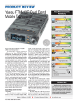
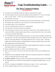
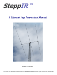
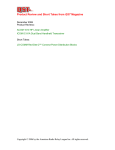
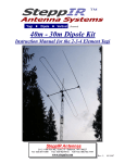
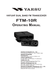
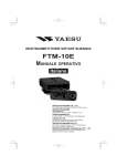
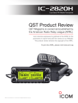
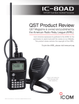
Product Review and Short Takes from QST Magazine May 2008 Product Reviews: Yaesu FTM-10R Dual Band Mobile Transceiver SteppIR 40-30 Meter Upgrade Kit Short Takes: Hendricks QRP Kits Long Wire Antenna Tuner Copyright © 2006 by the American Radio Relay League Inc. All rights reserved. product review Yaesu FTM-10R Dual Band Mobile Transceiver Key Measurements Summary 0.16 0.14 SINAD 0.25 0.1 Receiver Sensitivity (12 dB SINAD, µV) 96@10 MHz† , 79@10 MHz Rx 60 90 Receiver 3rd-Order Dynamic Range (dB) 62@20 kHz* , 59@20 kHz* Rx 40 70 Receiver 3rd-Order Dynamic Range (dB) 62 ChRej 50 Reviewed by Howard Robins, W1HSR ARRL Contributing Editor The FTM-10R is a rugged, weatherproof addition to the Yaesu VHF/UHF mobile product line. According to the ads, it’s aimed at outdoor motorsports enthusiasts. The waterproof control head can be separated from the main radio unit and is shown mounted on motorcycle handlebars (see sidebar). The main unit, which is not waterproof, could be stored in a saddle bag or mounted under a seat. The radio has many features, including some that distinguish it from the pack. For starters, it has a built-in AM and FM broadcast band receiver, wideband receiver coverage, weather band with alert, and 500 memory channels. Transmitter power is 50/20/5 W on 2 meters and 40/20/5 W on 70 cm. (The FTM-10SR is similar, but with 10 W on 2 meters and 7 W on 70 cm.) There’s a microphone built into the control panel, and it can be PTT or VOX activated. The FTM-10R is the first mobile radio I’m aware of that can work with Bluetooth wireless headsets. There’s also an intercom feature that lets two Bluetooth headset users talk to each other. I will get into detail about many of the special features later in this review. Good Things Come in Small Packages The radio body is compact, measuring about 1.5 × 4.25 × 5.5 inches (height, width, depth), and the detachable control panel is just over 1 inch deep. The body serves as a massive cast aluminum heat sink, so there is no cooling fan. The FTM-10R comes with hardware to support several mounting arrangements and a 3-meter-long separation cable. (An optional 20 foot separation cable is available for those bigger vehicles.) The control panel has a built-in mic, so a traditional hand mic is not necessary and not included with the radio. Yaesu offers two optional hand mics, one with a 16-key DTMF (dual-tone, multi-frequency) keypad, and one without. You can connect the microphone to the rear panel of the main unit or to the control panel with an optional adapter that connects to the bottom edge. (Note that the FTM-10R uses a special microphone connector, so you’ll need one of the optional Yaesu mics or adapters if you don’t want to use the built-in microphone.) The front of the control panel is fairly simple, with four push buttons, one twistknob and a brilliant, easy-to-read blue LCD. There are five additional push buttons on top. All push buttons are back-lit for easy visibility in the dark and are large and wellspaced for easier access by gloved fingers. I will get into how these buttons are used later in this review. The radio body has an RJ-45 jack on the front for connection to the control panel. The rear panel has an SO-239 RF connector, Mark J. Wilson, K1RO From May 2008 QST © ARRL Product Review Editor 59 Adjacent Channel Rejection (dB) 90 97 105 IF 60 135 IF Rejection (dB) 136*† Img 60 70 120 Image Rejection (dB) Snd 1 Audio Output (mW) 4.2† 4 pr031 2M Key: † Off Scale * Measurement noise limited at 70 cm value shown. Bottom Line Weatherproof, compact and rugged, Yaesu’s FTM-10R offers a number of features for motorcyclists and other nontraditional mobile operators. With VOX and Bluetooth capability, it brings hands-free mobile operation to the amateur marketplace. [email protected] external speaker jack, mic connector and dc power cord. There’s also a LINE IN jack for an external audio source, such as an MP3 player. There is an internal speaker in the radio body, and another in the control panel. Table 1 Yaesu FTM-10R, serial number 7G030319 Manufacturer’s Specifications Measured in the ARRL Lab Frequency coverage: Receive, 0.5-1.8, 76-222, 300-999 MHz (cell blocked); transmit, 144-148, 430-450 MHz. Receive and transmit, as specified. The FTM-10R comes with the control panel attached to the main unit and can be operated this way if you like. There’s a mounting frame between the control head and main unit, and out of the box it’s set up so that the two units are parallel. Yaesu supplies an angled mounting frame that tilts the control head up or down. This might improve viewing the display and operating the controls in some installations. I decided to separate the control head and main unit. To do that, I had to remove four little screws and unplug the short connecting cable. The mounting frame (one screw) and the rear panel cover (four more screws) were removed to attach the longer separation cable and install the BU-1 Bluetooth adapter to the control panel. Doing this reminded me of changing a battery in a waterproof watch — there is an O-ring gasket around the inside of the rear panel cover. The interface cable is physically locked into place inside the rear cover with a “binding plate” that slides into grooves that are cut into a waterproof grommet molded onto the cable. Once physically secured to the rear panel cover, the cable end is pushed onto pins on the panel’s printed circuit board. I am sure this complex assembly arrangement is necessary to preserve the water-tightness of the control panel. The Bluetooth unit is also pushed onto a PC board connector. You can mount the control head with a supplied hanger bracket or magnetic mount. Yaesu also offers an optional multi-angle bracket and the motorcycle handlebar bracket mentioned earlier. Power requirement: Receive, 0.5 A; transmit, 8.5 A (max); 11.7-15.8 V dc. Receive, 0.49 A; transmit, 7.2 A at 13.8 V; normal operation at 11.7 V. Modes of operation: FM. FM, AM (receive only). Receiver AM sensitivity: 10 dB S/N, 0.5-1.7 MHz, 5 µV; 108-137, 300-336 MHz, 0.8 µV. Receiver Dynamic Testing AM, 10 dB S+N/N: 1.0 MHz, 1.5 µV; 120 MHz, 0.2 µV. FM sensitivity, 12 dB SINAD: 137-150, 420- 470 MHz, 0.2 µV; 150-174, 336-420 MHz, 0.25 µV; 800-900 MHz, 0.4 µV; 900-999 MHz, 0.8 µV; WFM, 76-108 MHz, 2 µV; 174-222 MHz, 1 µV; 470-800 MHz, 5 µV. For 12 dB SINAD, 144 MHz, 0.16 µV; 440 MHz, 0.14 µV; WFM, 100 MHz, 1.1 µV FM two-tone, third-order IMD dynamic range: Not specified. 20 kHz offset: 146 MHz, 62 dB*; 440 MHz, 59 dB*; 10 MHz offset: 146 MHz, 96 dB; 440 MHz, 79 dB. FM two-tone, second-order IMD dynamic range: Not specified. 87 dB. FM adjacent channel rejection: Not specified. 20 kHz offset: 146 MHz, 62 dB; 440 MHz, 59 dB. S-meter sensitivity: Not specified. Max indication: 146 MHz, 8.4 µV; 440 MHz, 8.0 µV. Squelch sensitivity: 0.16 µV. At threshold: 146, 440 MHz, 0.13 µV. Menus and Controls *Measurement was noise limited at the value indicated. **Volume control is stepped; this is the closest step to 10% THD. Setting it Up One of the buttons on the top of the control panel is the PTT button. The control panel is small enough that you can handle it like a microphone or a handheld radio. The supplied hanger bracket or magnetic mount lend themselves to this method of operation. On-air testing demonstrated that the default mic gain setting was a bit too hot, and when dialed back a bit, provided perfect audio. For the most part, the FTM-10R menu programming is straightforward. Pressing the VOL/SEL key for 1 second gives access to 49 functions that are selected by turning the DIAL knob. Another button is used to activate or deactivate the selected function. So, 49 functions are adjustable using the same three buttons in the same way. In traditional Yaesu fashion the menu items are numbered, but also in alphabetical order, which makes scrolling through them to find what you are Receiver audio output: 4 W at 10% THD into 4 Ω. 4.2 W at 13% THD into 4 Ω.** Spurious and image rejection: Not specified. First IF rejection, 146 MHz, 97 dB; 440 MHz, 105 dB. Image rejection, 146 MHz, 136 dB*; 440 MHz, 70 dB. Transmitter Transmitter Dynamic Testing Power output (H/M/L): VHF, 50/20/5 W; UHF, 40/20/5 W. 146 MHz, 51/19/4.2 W; 440 MHz, 39/19/4.9 W. Spurious-signal and harmonic suppression: 60 dB. VHF, 65 dB; UHF, 63 dB. Meets FCC requirements. Size (height, width, depth): 1.5 × 4.4 × 7 inches; weight, 2.9 pounds. Price: $360; BH-1 headset, $90; BU-1 Bluetooth adapter, $75; CAB-1 charger sleeve, $10; MH-68B6J hand mic, $40; CT-M11 headset cable, $24. Note: Unless otherwise noted, all dynamic range measurements are taken at the ARRL Lab standard spacing of 20 kHz. looking for somewhat intuitive. In addition, buttons on top of the control head are used for what is called the “Smart Menu.” There are UP/DWN buttons that scroll through functions such as squelch level and transmit power level that are used more routinely. A third button, labeled F, changes the setting of the selected function. There is also a “Memory Set Mode” with 13 memory channel items that can be manipulated. This is where you can set the transmit power level for each channel, add alphanumeric tags, reassign channel numbers, and so forth. The clock also has its own set mode with six adjustable parameters. It also functions as a timer or stopwatch. Bluetooth and VOX Operation In recent years a lot of attention has been paid to developing tools for “hands free” cell phone operation. With the inclusion of VOX and Bluetooth features, operating the FTM-10R can be hands-free too. We ordered and installed the optional BU-1 Bluetooth adapter, the BH-1 Bluetooth headset and the CAB-1 charger sleeve (to charge the battery in the BH-1 headset). After installing the adapter and charger sleeve, the radio must be “paired” with the headset so that they recognize and communicate with each other. I found that the pairing instructions were incorrect in the printed manual that came with this radio. (You must power up From May 2008 QST © ARRL Motorcycle Mobile with the FTM-10R Hams have been installing mobile radios on motorcycles for years, but the FTM-10R is the first one we’ve seen that’s specifically designed to be bikefriendly. To find out more, we checked out the installations of Adam Koczarski, KA7ARK, of Bellevue, Washington, and Allan Buckshon, VE7SZ, of Langley, British Columbia. Adam and Allan both ride Honda ST1300 sport-touring bikes. The ST1300 has luggage carrying capability and is comfortable for long-distance touring, yet is suitable for spirited riding on twisty back roads. Allan picked up a pair of FTM-10Rs at Dayton last year, and he Figure 1 — The FTM-10R main unit is small enough to fit under the ST1300’s seat. Figure 2 — The FTM-10R control head mounts on the left handlebar of Adam’s bike, sharing the cockpit with a GPS receiver and other accessories to make long-distance travel more enjoyable. the radio while pressing the VOL/SEL button in order to get into the mode required for pairing.) I downloaded an updated manual from Yaesu’s Web site, and with the new instructions everything worked as expected. In addition to the BH-1, I tested two commercially available cell phone Bluetooth devices with great success. Bluetooth devices come with codes that need to be programmed into the radio in order for the pairing to work. My cell phone devices had codes different From May 2008 QST © ARRL and Adam installed them for the summer 2007 riding season. Adam installed his transceiver body under the seat (Figure 1). Along with other electronic accessories, it’s powered from an auxiliary fuse panel and noise filter. The control head is on a swivel mount on the handlebar (Figure 2). The antenna, a Comet CA-2x4SR dual-bander, mounts on a bracket attached to a luggage rack at the back of the bike. Inside his full-face helmet, Adam uses an Autocom headset. The Autocom communications system is a popular accessory for riders equipping their bikes with cell phones, MP3 ADAM KOCZARSKI, KA7ARK players, GPS receivers, FRS transceivers or other audio/ communications equipment. The only real difficulty encountered during installation was connecting the FTM-10R to the Autocom control box. At the time of installation, no connector, cable or information about the FTM-10R’s mic jack was available. Removing the element from an optional hand mic allowed a makeshift connection using the radio’s VOX feature. Yaesu has since introduced the CT-M11 accessory cable and an information sheet for connecting the transceiver to external headsets. Before next season, Adam and Allan plan to rewire their bikes using the CT-M11 cable and to hook up PTT through the Autocom system. How does it work? “Fine,” says Adam, KA7ARK. “The ability to listen to FM or my MP3 player and have the ham band audio cut in when receiving a signal is nice. There’s plenty of audio. The split system with the lightweight head on the bars is nice.” “The radio works well on 2 m and 440, and the FM band stereo receiver is good,” adds Allan, VE7SZ. “I have not used PTT, but I found the VOX to be excellent using the headset. It took a bit of adjusting, but I get great VOX response and few false trips at spirited motorcycle speeds. When I change to the CT-M11 cable I’ll look forward to adding PTT to have the ability to select either way. The control head has been weatherproof as advertised, and the controls can be ADAM KOCZARSKI, KA7ARK adjusted with gloves. That was the reason I purchased the radio, and I am happy with it.” For more photos, see Adam’s Web site at koczarski.com/ Motorcycles. Other motorcycle mobile resources include Chapter 4 in ARRL’s book Amateur Radio on the Move (order no. 9540; see your local dealer or www.arrl.org/shop) and the Motorcycling Amateur Radio Club (www.marc-hq.org). — Mark Wilson, K1RO, Product Review Editor from each other and from the BH-1. So, you need to consult the instructions that come with devices for their respective codes and how to get them into pairing mode. The FTM10R defaults to the code for the BH-1. The FTM-10R can be programmed to allow Bluetooth devices to work with VOX or with a PTT switch on the Bluetooth device. If you do not use VOX, you must push the PTT button on the BH-1 headset to transmit. I found this uncomfortable because pressing the PTT switch also presses the earphone into your ear. That can be improved with a menu setting that changes the PTT mode so that you don’t have to hold the PTT button (press it once to transmit, and again to return to receive). The manual describes this function in the context of the PA feature, but it also applies to transmitting with Bluetooth or control panel mic. I do not usually use VOX. It does work, but for me it took some getting used to. There are three VOX sensitivity settings available. VOX seemed to work well with the cell phone devices too. With VOX you need to be careful about your verbal reaction to the usual travel annoyances, such as an idiot cutting into your lane on the highway. Other Features AF Dual. With this feature turned on, you can monitor any covered amateur frequency while listening to the built-in AM/FM broadcast radio or an external MP3 player connected to LINE IN. You can also choose to listen to a programmed “Club Channel” (see below) while monitoring another amateur frequency. When signals appear on the amateur frequency, the radio automatically switches to it. While in AF Dual mode, the display flashes between the two frequencies being monitored. This feature probably would be better called “RF Dual,” since it monitors two radio frequencies while you listen to the audio of one at a time. Club Channel. This is an enhanced call channel that can be programmed to any frequency in the 2 meter or 70 cm bands. When Club Channel Monitor is activated, the preset club frequency is “watched” every 3 seconds. You can listen to broadcast radio, an external audio device or another amateur frequency while keeping an eye on the club channel. You can set an option to remain on the club channel after a signal is received there, or to go back to watch mode. Paging. The Enhanced Paging and Coded Squelch (EPCS) feature uses two stored CTCSS tones to open the receiver squelch, and encodes two other tones that are sent when you key the transmitter. When activated, a ringing bell sounds when the tones are received and the squelch is opened. EPCS is intended to keep the receiver quiet unless you’re called by someone transmitting the correct tones, presumably a friend or fellow club member. Each receiver in your group could be programmed with its own unique set of squelch tones, but doing so would require you to maintain a list and manually select those tones each time you paged an individual. From a practical standpoint EPCS might better be viewed as a group alerting/ calling system in which all members use the same tones. Note that if you are using a frequency that is shared with other users who are not part of your group, you could inadvertently interfere with them when you transmit. If the other users are not using your ECPS tones, their signals won’t open your squelch and you won’t know they are using the frequency. Messaging. This feature allows you to program and send text messages of up to 16 characters to a group of up to 20 members. The received message scrolls across the display on the receiving end. All members must be using the same club frequency and have the same group member list (IDs could be names or call signs). Up to 20 messages can be stored, and the same preprogrammed messages must be in the same slots in all of the group member radios. Messages are not sent through a repeater, and messaging cannot be activated when CTCSS, DCS or Pager are activated. Wireless Cloning. The FTM-10R can transfer settings and data to other FTM-10Rs so that they are all set up the same. This feature uses the Club Channel, which must be set in the 70 cm band for this function Weather band/weather alert. The FTM-10R is factory programmed with the 10 NOAA weather channels. The severe weather alert monitors for NOAA’s 1050 Hz tone alert. After turning this feature on, there is no indication of it on the LCD. Intercom. With Bluetooth enabled, riders and passengers can communicate with each other using Bluetooth headsets. This can be useful while wearing helmets or while in environments with high levels of ambient noise. Public Address. Attach an external speaker and select PA from the Smart Menu and you have an 8 W public address system. While in this mode, the PTT opens the mic but does not key the transmitter. WiRES. Yaesu’s Wide-Coverage Internet Repeater Enhancement System is supported in the Sister Radio Group (SRG) and Friends’ Radio Group (FRG) modes. ARTS. This feature uses DCS (digital coded squelch) signaling to alert users when they are within simplex range of each other. When activated, a subaudible DCS code is transmitted for one second every 25 seconds, or whenever the PTT is pushed. If another radio with this feature activated is within range, an audible beeper sounds (if enabled) and the LCD reads IN.RANGE . Polling signals continue until the ARTS feature is deactivated. Three beeps sound if you go out of range for more than one minute and OUT. RANGE is displayed. I had only one FTM10R to test for this review, so was unable to actually test the unique features that require two or more radios — paging, messaging, cloning and ARTS. Final Thoughts The User Manual was obviously written in another language and translated into English. I found some of the instructions confusing and needed to contact Yaesu for help. Customer service was responsive and helped me through my questions. Some errors we found have been corrected in the downloadable manual available from the Yaesu Web site. A newer version is said to be provided with new radios. There is no programming software or computer interface available or planned. Once I got used to the procedures, manipulating features was fairly easy. With 500 memory channels and so many special features, I think that programming software would help with keeping track of stored parameters and make updating more efficient to implement. It is clear that Yaesu had motorcycles, boats, recreational vehicles and other nontraditional mobile installations in mind when they developed this rig. The receive audio is powerful enough to be useful in noisy environments. The addition of Bluetooth and hands-free operation is something that I think we will be seeing more of in mobile radios. Use of VOX on repeaters is questionable in my opinion, but for on-the-road simplex operation, along with Bluetooth headsets, it should be a welcomed capability. M a n u f a c t u re r : Ve r t ex S t a n d a r d , 10900 Walker St, Cypress, CA 90630; tel 714-827-7600; www.yaesu.com. SteppIR 40-30 Meter Upgrade Kit Reviewed by H. Ward Silver, NØAX QST Contributing Editor In February 2003, I had the opportunity to review one of the just-introduced three element SteppIR Yagi antennas.1 For those of you who 1H.W. Silver, NØAX, “SteppIR Three Element Yagi Antenna,” Product Review, QST, May 2003, pp 67-69. Bottom Line SteppIR’s upgraded driven element provides rotatable dipole performance on 40 and 30 meters without compromising 20-10 meter performance. aren’t familiar with the SteppIR technology, the elements of this Yagi are adjustable in length. A special beryllium-bronze perforated tape is extended and retracted inside hollow fiberglass tubes by stepper motors (thus the name). There’s also an optional fixed element (a director) near the center that’s used for 6 meter operation only. In the shack, a microprocessor in the From May 2008 QST © ARRL H. WARD SILVER, NØAX a ntenna’s control box keeps track of how many “steps” have been pushed out or pulled in and thus the element length. The control box stores models for the dimensions of three element Yagis for all of the ham bands from 20 through 6 meters, plus a generic model for general coverage use anywhere between 14 and 54 MHz. As the frequency of operation changes, so does the length of all three elements. The control box can receive frequency information from the radio’s data interface, too! The operator can also reverse the antenna electrically (the “180°” feature) or have the antenna beam power to both front and back (the “Bi-directional” feature) at the touch of a button. The original three element design has been extended to include two and four element versions, and the frequency range expanded to 7 MHz in an aptly named version called the MonstIR. The SteppIR’s excellent performance, ability to tune any frequency from 20 through 6 meters, and the extremely useful Bidirectional and 180° features proved to be a winning combination in a run of top contest finishes from the Pacific Northwest. Adding Bands SteppIR introduced an upgrade to the basic 14-54 MHz design in 2006 that adds rotatable dipole performance on 30 and 40 meters. This is accomplished by folding the SteppIR conductive metal tape element back toward the boom through a tromboneesque bend at the end of the element. The overall length of the element is about the same, and it just looks like a pair of trombone slides connected end to end as shown in the lead photo. The new element adds little additional visual impact. For 14 MHz and higher frequencies, the tape is straight, just as in a regular Yagi. At the low end of 40 meters, the ends of the two tapes are nearly touching in the middle. From May 2008 QST © ARRL Below 20 meters, the reflector and director elements are retracted and are not part of the antenna. The fixed 6 meter element has no effect at these frequencies. When ARRL asked if I would be interested in reviewing the new SteppIR 30-40 Meter driven element as an upgrade to the beam, I jumped at the chance. My former station (and the SteppIR) are now owned by Mark Aaker, K6UFO, and he quickly signed on to the adventure. The station would offer a unique chance to evaluate the 30 and 40 meter capabilities of the upgraded antenna because about 70 feet away are a Cushcraft 40-2CD two element 40 meter Yagi and a full size 30 meter rotatable dipole at the same height (50 feet) on another free-standing tower. Mark placed the order and we were on our way. The 30-40 meter dipole options are proving quite popular and the weeks dragged by before our shipping notice finally appeared. Assembly Even though it was mid-winter in Seattle, the weather cooperated as Mark and I began the retrofitting project. First, the SteppIR had been up in the weather for five years. How did it look? Aside from one bit of the selfvulcanizing tape at a fiberglass tube junction unraveling, no mechanical wear and tear was visible. The antenna had never misbehaved, forgotten its models, jumbled up its sliding tape or failed to follow the controller’s orders. The sun had taken its toll on the coating of the fiberglass tubes, however. The green paint was completely gone in several spots. Close inspection revealed no serious damage to the tubes, however. SteppIR says that any good marine paint for fiberglass will work fine to make repairs of the finish. Two boxes were received from SteppIR. A big one had the necessary tubes, mounting bracket and motor housing. A smaller box contained the hardware, instructions and new controller firmware chip. Mark upgraded the firmware and did an inventory of the received materials. The big box’s contents were complete and agreed with the parts list. The small box’s contents did not; apparently we were short a few bolts and nuts. We decided that we could obtain anything missing at a local hardware store and so pressed on. The original driven element was disconnected, unbolted, and set aside (these parts can be reincarnated as a SteppIR dipole). The parts discrepancies were resolved during assembly. As it turned out, we were expected to use hardware from the original driven element. This wasn’t mentioned in the instructions possibly because this was one of the old-timer, original models. The upgrade kit is sold for two, three and four element Yagis, plus there are the two versions of the three element Yagi. Instructions to upgrade all four models (www.steppir. com/files/40-30manual.pdf) are combined in a single workflow. This requires some very, very careful reading before beginning the project. Understand the entire procedure and don’t rush. Make sure you understand exactly where and how each new bracket and hole will go before drilling or cutting. Measure at least twice and do a walk-through. If things don’t look right, stop and figure it out. Dimensional drawings are easy to misread at first until making careful comparison with the actual antenna. The instructions would have been much better with separate steps and checklists for each model. I found that a two-person team makes it a lot easier to figure out how to do things properly. After mounting the motor housing and brackets and reconnecting the control cable, we were instructed to perform the test function on the controller to extend and retract a few inches of tape. The motors fired up and copper beryllium tape spewed forth from the housings with no sign of stopping. “Mark, hold it!” The tape was retracted and tried again with the same results. We decided to retract the tape and proceed. This proved to be correct as the instructions were unclear about the test function. Installation The remainder of the trombone elements were assembled and then a new and interesting problem came up. On the three element Yagis, the new element is intended to encircle the mast as in Figure 3. Um. How is that supposed to happen up on the tower? If the SteppIR mounts on a short stub mast (if it’s the only antenna on the rotator) and a sufficiently long gin pole is used, setting the antenna down over the mast is easy. For crank-up towers as at Mark’s station or for installations with long masts, this could be a problem. Since it was getting dark (so far, the process had taken about four hours), we de- 6 Set for 7.05 MHz 5 SWR 4 Set for 7.2 MHz 3 2 1 7.00 7.05 7.10 7.15 7.20 Frequency (MHz) 7.25 7.30 Figure 5 — Here’s the 40 meter SWR with the driven element set to 7.05 MHz (blue trace) and 7.2 MHz (red trace). Figure 3 — For three element antennas, the completed driven element encircles the mast, requiring some installation ingenuity. Figure 4 — Temporary configuration for installation on the mast. Bend one unconnected tubing tip towards the motor housing and secure with tape. Once it is mounted on the mast, release the tip and install in the coupling to complete the assembly. cided to call it a day and get some guidance from SteppIR. They suggested that before completely assembling the element prior to reinstallation of the antenna, fold the end of one tubing section back toward the motor housing and hold it with tape as in Figure 4. Once mounted on the mast, the tubing could be installed in the coupler and assembly completed. This proved to be easier said than done and is highly dependent on the circumstances of the installation. On the tubular crankup tower Mark uses, it’s not easy to work on the antennas and rotator. Reaching out far from the tower and exerting any significant leverage is difficult. The crew managed to complete the job with some tipping and tilting and improvisation. My advice is to plan this step very carefully. Take it slow and if things aren’t working out, stop and revise the plan. Don’t get frustrated at this last step and compromise the assembly. Once assembled, we tested the element and it was good to hear the tape rushing through the tubes as we selected different bands. Mechanically, all was well. Performance What’s most important is, of course, “How does it play?” and “Does it screw up the rest of the antenna?” The answer to the first question is, “Fine,” and to the second, “No.” Operation on 20 through 10 meters seemed to be completely unaffected. SWR and front-to-back did not exhibit any noticeable difference from the original version. The 40 meter dipole seems to hold its own against the 40-2CD Yagi on contacts over moderate distances around the US. On DX contacts, more often the beam would have a slight, but not dramatic, edge. Obviously, the dipole has no front-to-back ratio! Both antennas are mounted at about 50 feet, less than 1⁄2 λ and too low for a Yagi to develop much of a pattern. If the antennas were higher, the difference might be more significant. On 30 meters, slightly over 1⁄2 λ up, there was little difference of note between the SteppIR element and the full-size dipole. The SWR on 40 meters was tunable to around 1.2:1 in any part of the band, as shown in Figure 5. As shown for two settings in the band, it can operate within a segment without retuning, if desired. On 30 meters, the straight dipole element has an impedance of about 50 to 70 Ω at resonance, depending on height. Because of the 2:1 transformer needed to match the lower impedance on the other bands, on 30 meters the antenna has a resonant SWR of about 1.5 to 2:1 anywhere in the band. On all bands except 30 meters the SWR was easily tuned to 1.2:1 or better, while on 30 meters the internal antenna tuner in the FT-1000MP MkV transceiver used at the station had no trouble bringing it to 1:1. Changing between 40 and 30 meters takes about 10 seconds. Changing from 40 meters to one of the higher bands can take a while — 15 seconds from 40 to 20, for example. This is not an instant-QSY antenna. Summarizing, the 30/40 meter driven element upgrade does exactly what it claims. It gives you rotatable dipole performance without affecting performance on the higher bands. The upgrade process was comparatively easy — a couple of hours to take it down, an afternoon of assembly and a couple of hours to reinstall. Material quality was excellent and the mechanical design appears to be robust. The instructions, while somewhat convoluted and in some need of reorganization, were sufficient for the careful builder to get the job done. If your station is limited to a single Yagi and multiple fixed, wire antennas are not an option, you will be satisfied with the upgrade’s performance. Manufacturer: SteppIR Antennas, 2112 116th Ave NE, Suite 2-5, Bellevue, WA 98004; tel 425-453-1910; www.steppir. com. Price: $490, plus $19 for an additional bracket needed for older antennas. From May 2008 QST © ARRL short takes Hendricks QRP Kits Long Wire Antenna Tuner One of the great pleasures of low-power (QRP) hamming is how easy it is to enjoy on the road. You can pack a transceiver and a battery or power supply in your luggage along with a roll of antenna wire and still have room for nonessential items… like clothing and personal hygiene products. If you’re fortunate enough to have a hotel room with a window that can be easily opened, you can set up a station with little more than a discreetly dangling wire in the fresh air and another wire tossed onto the floor (the “counterpoise”). Other than occasional inquiries from suspicious housekeeping people, the only problem you may encounter is matching the output of your transceiver to antenna. The RF output circuitry in your radio expects a 50 Ω impedance at the antenna jack, but a long hunk of wire swinging in the breeze can present almost anything other than 50 Ω at the feed point. That’s where an antenna tuner comes into play. It acts like a variable impedance transformer to provide the match you need to deliver the full output of your transceiver to the antenna. We tend to think of antenna tuners as bulky boxes, but they don’t always have to come in large packages. If you’re only running 5 W output, you don’t need a tuner rated at 1.5 kW. At QRP power levels, a tuner can do a fine job without large, robust components. The Hendricks QRP Kits SLT antenna tuner is a prime example. At only a couple of inches across, it is specified to handle up to 10 W of RF power without breaking a sweat. Unlike most antenna tuners, you can carry the SLT in your pocket, although it might raise eyebrows during an airport security screening. (“It’s called an ‘antenna tuner.’ Really!”) The best part of the SLT, aside from its performance and price, is the fact that you get the pleasure of building it yourself. This is strictly a single-evening kit that even a beginner can handle. What’s Inside? SLT stands for Switched Longwire Tuner. It’s an L-network coupler built around a polyvaricon tuning capacitor and five toroid coils. The toroids are switched in and out of the circuit with a row of toggle switches. If your transceiver has a built-in SWR meter, that’s fine. If not, the SLT provides a clever alternative thanks to an LED SWR indicator developed by Dan Tayloe, N7VE. The bright red LED glows when mismatch conditions are high and dims or goes out altogether when a 50 Ω match is achieved. The SLT kit contains just a handful of Internal view of the SLT. Steve Ford, WB8IMY From May 2008 QST © ARRL QST Editor parts. The five toroids are of the single-wire variety and simple to wind. There is one bifilar toroid transformer, but the winding is straightforward. The downloadable PDF instructions show you how to go about it. The only potential difficulty involves the aluminum case. There is a downloadable drilling template on the Hendricks QRP Web site. You have to print the template at the proper size to fit the case and then mark and drill the holes very carefully. The board components are packed tightly and there is little room for error. Take particular care with the holes you drill for the wire binding posts and the BNC coax jack. If you make a mistake you may find that you don’t have enough interior space between the connectors and the circuit board. How Does It Work? In one word: easily! You simply flip all the toroid toggle switches to OUT, the TUNE/ OPERATE switch to the TUNE position, apply power and twist the tuning capacitor knob until the LED dims or winks out. If the LED won’t extinguish, toggle the right hand-most toroid to the IN position and repeat. Still no joy? Add another toroid. Keep it up until you achieve a match and then flip the SLT TUNE/OPERATE switch to OPERATE. That’s it. The SLT is an absorptive bridge with hefty resistors to keep your transceiver happy as you find the right impedance. You don’t have to worry about frying your finals. I’ve used the SLT in hotels, during hikes and at home. With the SLT to match my QRP rig to a 50 foot wire (and an equal length counterpoise wire attached to the grounded antenna post), I’ve worked stations all over the country and some DX to boot. Manufacturer: Hendricks QRP Kits, 862 Frank Ave, Dos Palos, CA 93620; tel 209-704-3522; www.qrpkits. com/. $40. [email protected]