1
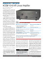
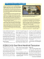
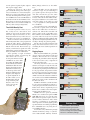
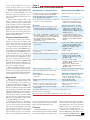
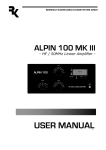
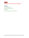
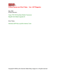
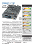
Product Review and Short Takes from QST Magazine December 2006 Product Reviews: ACOM 1010 HF Linear Amplifier ICOM IC-91A Dual Band Handheld Transceiver Short Takes: JO-COMM Red-Dee-2™ Connect Power Distribution Blocks Copyright © 2006 by the American Radio Relay League Inc. All rights reserved. PRODUCT REVIEW ACOM 1010 HF Linear Amplifier Reviewed by Mark Wilson, K1RO QST Product Review Editor By now most everyone is familiar with ACOM, the Bulgarian company that hit the ground running with the top-of-the-line model 2000A legal-limit autotune HF amplifier in 1999 and followed up a few years later with the model 1000, a manually tuned 1 kW amplifier for 160 through 6 meters. Both of these amplifiers have been reviewed favorably in QST.1,2 You might think that ACOM’s next amplifier would be an entry in the popular 1500 W manually tuned category. After all, these workhorses are found in ham shacks across the nation. Sorry, no. ACOM’s newest model, the 1010, goes in a completely different direction. Upon reflection, that’s not particularly surprising. Remember, this is the company that sent a high dollar legallimit autotune amplifier as its first entry in the US market. You Can Take It with You As noted in the ACOM 1000 review, there is a market for smaller, more portable amplifiers that can be whisked off to a distant land for a DXpedition or contest operation. The 1000 found its way into quite a few Pelican cases, but it’s still big enough and heavy enough that hauling it around gets old after a while. The 1000 was also a hit at home. Not every home station needs the legal limit, and some just don’t have the space or power source required. ACOM’s new 1010 is an amplifier that’s been put on a serious diet. At just under 40 pounds, it makes the 49 pound 1000 seem porky. It’s about half an inch wider than the 1000, but ACOM shaved 1.3 inches off the height and 1.6 inches off the depth. The 1010 is also about $900 less than the 1000 at current pricing. That would go a long way toward a compact transceiver or some antennas to round out your portable station. The 1010 reminds me of a Heath SB-200 I once owned, but with modern capabilities and features. I know, I know. We grew up thinking Table 1 ACOM 1010, serial number 050160 Manufacturer’s Specifications As specified. Power output: 700 W PEP or 500 W continuous carrier. As specified for SSB and CW. Driving power required: 50 to 70 W for rated output. 60 W typical. Input SWR: Less than 1.3:1. As specified. Output matching: Up to 3:1 SWR. Not tested. Spurious signal and harmonic suppression: 50 dB below rated output. 53 dB. Meets FCC requirements. Intermodulation distortion (IMD): –35 dB. 3rd/5th/7th/9th order (worse case): –37/–53/–56/–62 dB PEP. Primary power requirements: 85-132/170-264 V ac (in eight user settable taps). Size (height, width, depth): 5.9 × 16 × 12.4 inches; weight, 39.7 pounds. Typical retail price: $2340. heavier is better when judging RF amplifiers. That’s fine as long as you don’t have to move the beast once it’s in place on your operating table. So what does the 1010 give up in exchange for its svelte packaging and lower price? The short answer is about 300 W output, full break-in CW (QSK) and 6 meter coverage. The 1010 uses the Svetlana 4CX800A (GU74B), a popular Bottom Line 1D. Sumner, “ACOM 2000A HF Linear Amplifier,” Product Review, QST, May 2000, pp 64-66. QST Product Reviews are available on the Web at www.arrl.org/members-only/prodrev/. 2M. Wilson, “ACOM 1000 HF + 6-Meter Linear Amplifier,” Product Review, QST, Nov 2002, pp 70-72. Measured in the ARRL Lab Frequency Range (US units): All amateur frequencies, 1.8 to 30 MHz. This compact and reliable 700 W, 160 to 10 meter amplifier is sized for traveling, but it’s a good solution for your home station too. Mark J. Wilson, K1RO Product Review Editor and inexpensive ceramic/metal tetrode with 800 W plate dissipation. The 1000 uses that same tube to deliver 1000 W output on 160 through 6 meters, but the 1010 is scaled back to 700 W PEP for SSB and CW and 500 W for RTTY or other continuous carrier modes on 160 through 10 meters. Like the 1000, the 1010 uses a broadband tuned input circuit and a π-L output circuit that works over a broad range (SWR up to 3:1). Unlike the 1000, there is no provision for QSK, but the 1010 adds built-in switching for two antennas a fair trade in my book. The 1010’s front panel includes the usual TUNE and LOAD controls and BAND switch. There’s a power switch and push buttons for OPERATE/STANDBY and RTTY (to lower the [email protected] From December 2006 © ARRL power for continuous operation). Antennas are selected by a push button labeled A1 A2. All metering, tuning and status monitoring is handled by rows of LEDs. The rear panel includes a phono jack labeled KEY IN for the TR key line from your transceiver (ground to transmit). SO-239 connectors handle RF INPUT, ANT1 and ANT2. The ac power cord is detachable, something I’ve not seen on a power amplifier before. That makes packing easier, and if you travel a lot you can make up power cords with a variety of connectors for quick swaps. Metering and Protection Although the 1010 doesn’t have analog meters or fancy LCD panels, quite a bit of information is available on the front panel. During normal operation, the top row of LEDs displays peak forward power. The range is 50 to 800 W with 50 W resolution. Below that, a shorter row of LEDs shows 30 to 240 W reflected power, with 30 W resolution. Four other LEDs to the right of the reflected power indicators are labeled G1, G2, IP and F. The first three illuminate to let you know if you exceed the safe limits for control grid, screen grid or plate current. When these light, you need to reduce drive power or touch up the tuning controls. If you continue to operate the amplifier with excessive grid or plate current, or with excessive reflected power, the red F LED lights up and the amplifier switches to the standby mode. The 1010 returns to the operate mode automatically after a few seconds, but it will switch to standby again if the problem persists. Pressing the OPER and RTTY buttons simultaneously switches the upper row of LEDs to the service mode. In the service mode, the LEDs are used to observe approximate values of control grid current, screen grid voltage and plate current (plate plus screen grid). The service mode indicators are intended for troubleshooting and checking operating parameters, not for normal operation. As described in the next section, you don’t need to watch the plate current during tune-up or on-air operation. Portable environments can be hard on equipment, but the 1010 is prepared. The amplifier can work with poor antenna systems presenting up to 250 W reflected power. The ac power supply tolerates low line voltage and voltage spikes over a wide range, as well as short duration (100 ms) RF spikes from the transceiver. The amplifier incorporates TR sequencing, and inrush current is limited when the power is turned on. Putting the 1010 to Work The 1010 ships in a single carton with the tube and transformer installed. Units are From December 2006 © ARRL Figure 1 — Inside the ACOM 1010. normally set up for 240 V ac operation, but you can change that to 100, 110, 120, 200, 210, 220 or 230 V ac by moving jumpers on a PC board. Some soldering is required, but it’s not difficult and ACOM provides color photos of the jumper locations for each setting. You’ll need to provide a suitable power plug for your station, readily available at your local hardware store. As required by FCC rules, likely changing as we go to press, amplifiers destined for the US have 10 and 12 meter operation disabled. If you contact ACOM with proof of your amateur license, they will supply instructions for enabling operation on these bands. It’s not difficult but requires removing the cover. Hooking up the 1010 to my transceiver and antennas was straightforward. The manual recommends letting the amplifier sit for a few hours after unpacking it or moving it from a cold place to a warm place. The concern is that condensation may form inside the amplifier and cause high voltage arcing. When you first press the power switch, the amplifier performs some self-testing and the OPERATE LED flashes green during a 150 second warmup period. Once the LED stays green the amplifier is ready for operation. The tune-up process is similar to the ACOM 1000, making use of a “true resistance indicator” (TRI) circuit rather than the more traditional method of dipping the plate current and peaking the output. First preset the LOAD and TUNE controls according to a chart in the manual. Apply 10 to 20 W drive and adjust TUNE for maximum output power. Next, watch the TRI indicator (three LEDs above the LOAD knob) and adjust LOAD until the green LED in the center illuminates. If the yellow LED on the left side of the TRI display lights, turn the LOAD control to the right. If the one on the right side lights, turn LOAD control to the left. When just the green LED in the center is lit, increase drive power until the power output is 700 W or the desired level. Then touch up the TUNE control for maximum output and, if needed, use LOAD to center the TRI indicator again. In practice, the tuning tracked very well and required only minor adjustments at full power. With a little practice, tune-up is a snap. After years of dipping the place current with other amplifiers, I just needed a little mental reprogramming to get used to the procedure. For the most part tuning ranges were broad and smooth. I found that the LOAD control required a delicate touch on 10 meters, but the 1010 is forgiving of momentary misalignment. Instruction Manual The 18 page instruction manual is clear and well illustrated. It includes a lot of information on using and caring for the 1010. There’s a section detailing theory of operation, ACOM 1010: From (K7)C to Shining (WRT)C The ACOM 1010 amplifier was an important part of both the K7C DXpedition to Kure Atoll (www.cordell.org/ KURE/) in September and October 2005 and my recently completed WRTC 2006 operation in Brazil (www.wrtc2006. com) as PW5Q with Chris Hurlbut, KL9A. In both cases, the amplifier gave a very good account of itself and proved to be reliable and tolerant. Even though operated in conditions stressful to the amplifiers (hot and sandy on Kure) and to the operators (quick setup and new antennas for WRTC) there were no failures. The ACOM packs a lot of punch in a reasonably sized package. For DXpedition travel, the amplifiers fit in a single shipping case and could be easily transported. The amp meets the size and weight requirements for checked baggage, even with a shipping case. The 700 W output is only half an S-unit down from a full gallon. This power level proved to be perfectly sufficient for controlling pileups from Kure and starting pileups from Brazil. Over the 12 days of nearly continuous operating from broiling tents on Kure, the amps put out full power at all times. Tuning the ACOM is greatly assisted by the LOAD “centering” indicators (TRI feature) and the LED forward/reflected power output displays. At WRTC, quick band changing was very important. After we marked the TUNE and LOAD presets on the front panel, it was a simple matter to switch and touch up the LOAD control in a few seconds. The handful of times we transmitted on the wrong antenna or did some other dumb thing, the protective circuitry prevented any damage to the amp, taking it off-line and reactivating it a few seconds later. as well as a simplified schematic diagram. According to the manual, detailed schematics are available from ACOM upon request. The manual offers quite a few warnings and cautions, and they’re well worth reading to avoid hurting the amplifier or yourself. The only thing I found a little surprising is in the Tube Replacement section. The manual notes that tube replacement is a “complex and potentially dangerous operation that involves adjustment of the plate idling current. This should not be attempted by the user.” Parting Thoughts The ACOM 1010 performed very well JAN-ERIC REHM, SM3CER Figure A — Chris, KL9A, operating at PW5Q with the compact ACOM 1010 amp located between the run (left) and multiplier (right) stations. Aluminum foil on the shelf provided a temporary RF ground for the amp and filters. Anyone who has set up a portable or temporary station knows that compromise antennas are often required or the circumstances of installation may cause uncomfortably high SWR at times. The ACOM’s ability to tune up and operate with a significant amount of reflected power (up to 250 W) was important at both K7C and PW5Q. We did not have to spend valuable time trying to move an antenna’s low SWR point — we just operated! While at home I’m an enthusiastic low-power or QRP operator, on contest or DXing expeditions it’s important to put out a strong signal to be heard clearly. The ACOM 1010 allows you to accomplish just that without breaking the bank or your suitcase arm. — Ward Silver, NØAX in my home station. The 1010 seems to loaf along at its rated 700 W on SSB/CW and 500 W on RTTY. I’d rate the fan noise as average. Although it isn’t bothersome, it is more noticeable than other ACOM amplifiers I’ve used. At first I was a bit skeptical of using rows of LEDs rather than analog meters for tuning and operation. With the 1010 tuned up according to the procedures outlined in the manual, I used the service mode to check grid current and plate current. The parameters were always within the normal ranges outlined in the manual, so after a while I realized that I should just oper- ate and rely on the LEDs and protection circuitry to let me know if anything runs amok. When one of the yellow LEDs on the TRI indicator starts to flicker, it’s time to touch up the LOAD control or readjust the antenna tuner. Of course the 1010 really shines away from home. QST Contributing Editor Ward Silver, NØAX, describes his experiences in the sidebar “ACOM 1010: From (K7)C to Shining (WRT)C.” US Distributor: ACOM International, 4 Marc Rd, Medway, MA 02053, tel 508533-7665; fax 508-533-7707; www.hfpower. com. ICOM IC-91A Dual Band Handheld Transceiver Reviewed by Dan Henderson, N1ND ARRL Regulatory Information Specialist Small enough to fit in your coat pocket, the IC-91 comes in two flavors. The model reviewed is the IC-91A, a traditional analog dual band handheld FM transceiver with 5 W of power on transmit, a wideband receiver and a host of other features. ICOM also offers the IC-91AD, which incorporates D-STAR digital voice and data features. An IC-91A can be upgraded to a D-STAR capable ’AD version with the optional UT-121 digital unit. See the June 2005 Product Review column for more information on the D-STAR system.3 3W. Silver, “D-STAR Digital Voice and Data — An Overview,” Product Review, QST, Jun 2005, pp 67-69. This column also includes testing of the UT-118 digital voice module with an ICOM 2 meter handheld. QST Product Reviews are available on the Web at www.arrl.org/ members-only/prodrev/. Charge it Up Like most modern handhelds, the IC91A uses a compact, high capacity lithiumion battery pack. A full charge for the 7.4 V, 1300 mAh battery pack takes about 6 hours with the included BC-167A/D wall charger. If you want something quicker, try the optional BC-139 drop-in charger for a full charge in about 2.5 hours. The battery also charges whenever the radio is connected to a 10 to 16 V dc source, and ICOM offers From December 2006 © ARRL several optional cigarette lighter adapters and dc power supply cables. The IC-91A operates at 5 W on high power and 0.5 W on low power and incorporates several features to conserve battery life. Radio specs call for approximately 5 hours of battery life during normal analog operation on VHF and 4.5 hours on UHF. Subtract about half an hour for the D-STAR version. Those figures are based on 10% high power transmit, 10% receive and 80% standby and will vary with actual operating habits. The N1ND Reality Test As noted in previous reviews, my very first “reality test” for a new radio is “how quickly can I get on the air with it and have some fun?” Options and features are nice, but the bottom line for any radio is the ease with which you can use it to communicate. The IC-91A has the usual assortment of function keys that allow you to program and operate the radio. There’s a dual function knob on top of the unit and PTT and squelch buttons on the left side. Even for basic operation you will want to spend some time familiarizing yourself with the most commonly used buttons and combinations. After spending a couple of minutes reviewing the manual, I powered up the radio and set out to access a local repeater. First, I selected 144 MHz as my active VFO by pushing the MAIN button located directly beneath the PWR button until the main display showed the desired band. Then I used the larger dial on top of the radio, turning it until the desired frequency was displayed. A quick adjustment of the VOL control (a real knob that turns instead of up and down push buttons) and I was ready to give the IC91A what my From December 2006 © ARRL Elmer jokingly referred to as “the smoke test.” I keyed the mike, gave my call sign and waited for a reply. As you would hope, I got a quick response and enjoyed a brief chat with a friend who gave the audio good marks. After the initial operation on 2 meters, I tried 70 cm with similar results. I was pleased with the received audio of the radio. The quality of the audio was solid — very acceptable for a small speaker built into a handheld. I was struck by how comfortable the IC-91A felt to operate. Some of the handhelds on the market have an almost toodelicate feel, almost like razor-thin cell phones. Others really seem bulky in my hand, similar to the handhelds of decades ago. This radio fit nicely into my hand without an awkward feeling. With the belt clip attached, its light weight didn’t leave me needing to hitch up my pants frequently. The IC-91A passed the initial test with flying colors and it was time to move on to examining the more detailed operations of the radio. 0.14 0.12 0.1 SINAD 0.25 Receiver Sensitivity (12 dB SINAD, µV) 65@10 MHz I3 73@10 MHz Rx 60 90 Receiver 3rd-Order Dynamic Range (dB) 56@20 kHz I3 55@20 kHz Rx 40 70 Receiver 3rd-Order Dynamic Range (dB) 59 59 ChRej 50 90 Adjacent Channel Rejection (dB) 119 † Digging Deeper Most modern handhelds in a particular category offer nearly identical “bells and whistles.” That said, the ease of selecting and using the particular features important to the user becomes a key component in choosing the right radio. One thing I look for is the ease with which I can navigate not only the radio, but also the instruction manual. ICOM does an excellent job of presenting the information in its 124 page manual, along with clear illustrations and good step-by-step instructions. The only addition I would make is an index. A PDF version of the manual is available for free download from www.icomamerica. com and is worth a look to understand all that this radio offers. ICOM has included a useful and intuitive on-screen programming system for accessing the special features in the IC-91A. It takes more effort to explain the process than it does to actually select and set up the features from the MENU screen. DTMF and tone squelch (CTCSS/ DTCS), once considered an option in VHF/ UHF FM transceivers, are now the norm. More and more repeaters require a tone for access to reduce interference and to allow frequency coordinators to accommodate more repeaters in an already tightly packed spectrum. The IC-91A makes programming these subaudible tones easy using the onscreen MENU function. You needn’t worry about having enough channels for memory storage, as you have some 1300 available. Memory channels 101 110 IF 60 IF Rejection (dB) 94 95 Img 60 110 Image Rejection (dB) 245 Snd 100 245 800 Audio Output (mW) 194 194 T-R 250 pr014 50 Tx-Rx Turnaround Time (ms) 70 cm Key: † Off Scale 2M Bottom Line The ICOM IC-91A handheld transceiver packs good performance, ease of operation, wide receive coverage and optional digital voice in a convenient package. can be sorted into banks for ease of use. In each memory channel, you can store everything needed to use a specific repeater — frequency, mode, duplex direction and offset, any required subaudible tones for encoding or squelch, assignment to a specific memory bank for scanning and even a memory name. Another fairly standard feature is the ability to transfer (“clone”) settings and memories from one radio to another. With the IC-91A this is easily accomplished using the optional OPC-474 cloning cable. ICOM’s optional RS-91 Windows software handles memory management and remote transceiver operation. It also provides for low-speed data communication if your radio includes the digital module. An Amateur Band Receiver Plus... The IC-91A receiver has two “bands.” With the “A” band you can transmit on the 2 meter and 70 cm amateur bands. Receive range is really wide. You can listen to FM on the ham bands through 902 MHz, AM shortwave broadcasts, AM and FM broadcast bands, VHF aircraft band and NOAA weather channels, plus the usual VHF/UHF services. As shown in Table 2, receiver sensitivity is good across most of the range. The “B” band is more for ham radio, with transmit coverage on 2 meters and 70 cm and receive coverage from 118 to 174 and 350 to 470 MHz. With the DUAL WATCH function enabled, you can monitor two frequencies simultaneously (they can be on different bands). The IC-91A makes it simple to access the 10 preprogrammed NOAA weather channels. It’s also easy to set up the radio to monitor the weather channel in the background and notify you when NOAA issues a weather alert. Digital Capable While the review radio did not include the optional UT-121 digital module, I did have an opportunity see and briefly use an IC-91AD with digital capability. The module allows the radio to use digital voice and data communication through D-STAR system repeaters being marketed by ICOM. Although D-STAR repeaters are growing in popularity in many parts of the country, I’m not aware of any 2 meter or 70 cm D-STAR repeater systems in central Connecticut and didn’t have an opportunity to fully explore the digital additions to the radio. In addition to digital voice, the UT-121 adds the capability to interface with a GPS receiver so position data can be transmitted and received. It adds a digital recorder that can capture 30 seconds of receive audio. With the digital recorder, you can preprogram automatic responses for your radio, such as your call sign and information mes- Table 2 ICOM IC-91A, serial number 2501359 Manufacturer’s Specifications Measured in the ARRL Lab Frequency coverage: Receive, 0.5-999 MHz (cell blocked), transmit, 144-148, 420-450 MHz. Receive and transmit, as specified. Modes: FM, AM (receive only), WFM (receive only), DV (with optional module). As specified. Power requirements: 10-16 V dc; receive, 0.34 A; transmit, 2.2 A (max, high power). Receive (max vol, no signal), 0.23 A, 0.34 A when charging the battery; transmit, 2.0 A (13.8 V dc and batt). Receiver Receiver Dynamic Testing AM sensitivity: 10 dB S/N, 0.5-5 MHz, 1.3 µV, 5-30 MHz, 0.56 µV, 118-137 MHz, 0.5 µV, 222-247 MHz, 0.79 µV, 247-330 MHz, 1.0 µV. 10 dB S+N/N, 1-kHz tone, 30% mod: 1 MHz, 0.42 µV; 3.9 MHz, 0.41 µV; 14 MHz, 0.43 µV; 53 MHz, 0.45 µV; 120 MHz: 0.47 µV; 146 MHz, 0.33 µV; 440 MHz, 0.43 µV. FM sensitivity: 12 dB SINAD, 1.6-30 MHz, 0.4 µV, 30-118 MHz, 0.25 µV, 118-174 MHz, 0.18 µV, 174-350, 470-600 MHz, 0.32 µV, 350-470 MHz, 0.22 µV, 600-999 MHz, 0.56 µV; WFM, 76-108 MHz, 1 µV, 175-222 MHz, 1.8 µV; 470-770 MHz, 2.5 µV. For 12 dB SINAD, 29 MHz, 0.16 µV; 52 MHz, 0.18 µV; 146 MHz, 0.12 µV; 222 MHz, 0.19 µV; 440 MHz, 0.14 µV; 902 MHz, 0.23 µV; WFM, 100 MHz, 0.85 µV. FM two-tone, third-order IMD dynamic range: Not specified. 20 kHz offset: 29 MHz, 54 dB; 52 MHz, 57 dB*; 146 and 222 MHz, 55 dB; 440 MHz, 56 dB; 902 MHz, 52 dB*. 10 MHz offset: 146 MHz, 73 dB; 440 MHz, 65 dB. FM two-tone, second-order IMD dynamic range: Not specified. 146 MHz, 67 dB. FM adjacent-channel rejection: Not specified. 20 kHz offset: 29 MHz, 60 dB; 52 MHz, 57 dB; 146 MHz, 59 dB; 222 MHz, 61 dB; 440 MHz, 59 dB; 902 MHz, 52 dB. Spurious response: VHF, 60 dB; UHF, 50 dB. IF rejection, 52 MHz, 34 dB; 146 MHz, 101 dB; 440 MHz, 119 dB; 902 MHz, 100 dB. Image rejection, 52 MHz, 86 dB; 146 MHz, 95 dB; 440 MHz, 94 dB; 902 MHz, 6 dB. Squelch sensitivity: Not specified. At threshold, VHF, 0.35 µV; UHF, 0.4 µV. Audio output: 200 mW at 10% THD into 8 Ω. 245 mW at 10% THD into 8 Ω. Transmitter Transmitter Dynamic Testing Power output: VHF and UHF, 5.0 W high; 0.5 W low. With battery pack, VHF, 5.1 / 0.6 W; UHF, 4.5 / 0.5 W; with 13.8 V dc: VHF, 5.0 / 0.5 W; UHF, 5.2 / 0.4 W. Spurious signal and harmonic suppression: 60 dB. VHF, 67 dB; UHF, 72 dB. Meets FCC requirements. Transmit-receive turnaround time (PTT release to 50% of full audio output): Not specified. Squelch on, S9 signal, VHF and UHF, 194 ms. Receive-transmit turnaround time (tx delay): Not specified. VHF, 123 ms; UHF, 92 ms. Size (height, width, depth): 4.1 × 2.3 × 1.3 inches; weight, 10.6 ounces. *Measurement was noise limited. Typical retail price: IC-91A, $369; IC-91AD, $525, UT-121, UT-121, $199. sages. You can also use the UT-121 module to do the equivalent of low-speed text messaging using the D-STAR protocols. Thumbs Up I found the ICOM IC-91A to be an exceptional dual band Amateur Radio handheld. It is relatively intuitive to program and use. It will meet most needs of the newcomer or experienced amateur looking for reliable local communications on 2 meters and 70 cm, and the wide receiver coverage allows you to listen to a variety of bands and services. Manufacturer: ICOM America, 2380 116th Ave NE, Bellevue, WA 98004, tel 425454-8155; www.icomamerica.com. From December 2006 © ARRL SHORT TAKES JO-COMM Red-Dee-2™ Connect Power Distribution Blocks Larry Wolfgang, WR1B Senior Assistant Technical Editor [email protected] I have been using Anderson Powerpole connectors for all my radio equipment for a number of years. When making a mobile radio installation, I install fuses at both positive and negative battery terminals and run 8 or 10 gauge wire through the firewall to connect the radio. With Anderson Powerpole connectors on that wire, it is a simple matter to connect the mating Powerpole connectors to any of my radios. What could be more convenient? Recently I ran into a problem with this installation, however. My wife, WB3IOS, and I were participating in an ARES Recon Rally. This was a kind of scavenger hunt designed to familiarize us with important landmarks and possible shelter locations. The idea is that if we would be called upon to help with a communications emergency in that area, we would be at least a little familiar with the country roads, schools, town halls and other locations where we might be sent. We were about to be sent off on the scavenger hunt when one of the organizers approached me and asked if we would carry an APRS tracking unit. That way they could keep an eye on where we were driving, and call us back if we made too many wrong turns. It seemed like a great idea, so I agreed. Now came the problem, however. We were handed a 2 meter radio, mag-mount antenna, GPS receiver and packet TNC to install in the car. These required a source of 12 V dc. Of course, I did not want to disconnect my existing 2-meter radio because we needed that to call our reports in to the net control station as we logged our “discoveries.” I needed a way to connect the additional equipment to my power cable. I solved the problem with a couple of heavy duty clip leads (aka jumper cables) and some electrical tape, but it was not a pretty sight! The Ree-Dee-2TM Alternative I kept thinking about a better solution to this problem. In my shack, I have a West Mountain Radio RigRunner strip, and it is a simple matter to plug several radios and accessories into that strip to run from my 40 A switching power supply. I thought about buying a second RigRunner, but even the smallest strip seemed like too much of an investment for an occasional use. Besides, I really don’t need the additional fuses that are included in those power strips. All of the radio power cords have their own fuses, and I have the main power lead fused at the battery. Then I noticed the Powerwerx ad in QST for the JO-COMM Red-Dee-2TM Connect blocks. The ad shows the PS-4 Plus, which is four pair of Anderson Powerpole connectors arranged in a “plus” or “X” configuration as well as the PS-4 and PS-8, which have the connectors arranged in a block, with two or four pair of connectors on either end. These looked like the ideal solution to my problem. In fact, they were, and still are, perfect. Steve Ford, WB8IMY From December 2006 © ARRL For this review, I tried a PS-4 Plus, four-pole connector and a PS-8, eight-pole connector. Each connector block provides pairs of Anderson Powerpole connectors mounted in a small plastic housing. The Powerpole connectors are arranged in the “standard” red right, tongue top configuration. Inside that housing a heavy copper bus bar connects all of the red Powerpole connectors, and another connects all of the black Powerpole connectors. This ensures that the connector block can easily handle the 45 A maximum current rating of the devices. They are also rated at up to 58 V dc. I did not attempt destructive testing, but the plastic housing looks like it will withstand being dropped or having something dropped on it. I wouldn’t expect it to survive driving over it with a car, but it almost looks strong enough to endure that abuse as well. The blocks come with a 1-year warranty against any defects or malfunctions caused by workmanship or material failure. One nice feature of the PS4 and PS-8 blocks not obvious in the ad picture is that the pairs of Powerpole connectors have a bit of space between them. This means that it is a simple matter to plug in several radio or accessory connectors. If the connector block had put the Powerpoles together in a single block (like I did on the back of my 40-A switching power supply) then you would have to slide the radio-lead connector bodies together as well. This is a significant advantage in the way the blocks are built. I used the blocks on Field Day to connect my Elecraft K2/100 and KAT-100 automatic antenna tuner to the battery I used to run the station. When I wanted to make a couple of contacts with my 20 meter Rock Mite, I simply plugged that power cord into the distribution block and I was ready to go. If it hadn’t been raining so hard all weekend, I would also have been able to plug the lead from my solar panel into the connector block to add some energy back into the battery during the day. What could be easier for making power connections? In addition to the connector blocks with all Anderson Powerpole connectors, there are also blocks available with one OEM T connector, to mate with the connector supplied on many mobile radio power cords. The PS-6TE is a strip of 6 Powerpoles mounted vertically along the strip, with a 15 A OEM T connector on one end and a 30 A Euro connector on the other. The PS-75/45-4 block has a 75 A Anderson Powerpole pair on one end and four 45 A connectors on the other end. This is ideal for running an AWG no. 8 or larger wire from a car battery for power distribution inside a vehicle. Red-Dee-2TM connect blocks are patent pending. Red-Dee-2TM Connect power distribution blocks are manufactured by JO-COMM, 14131⁄2 West Kenneth Rd #122, Glendale, CA 91201 and are distributed by Powerwerx (www.powerwerx. com), 555 W Lambert Rd, Brea, CA 92821. PS-4 and PS-4 Plus, $14.95. PS-8, $24.95. QST Editor [email protected]