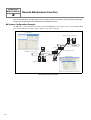
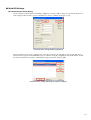
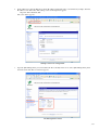
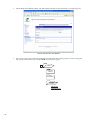
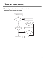
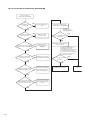
1
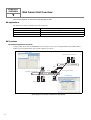
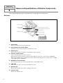
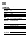
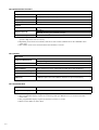
FC9Y-B919
FC4A SERIES
MICROSmart
Web Server Unit
Instruction Manual
PRECAUTIONS
●
Read this user’s manual to make sure of correct operation before starting installation, wiring, operation,
maintenance, and inspection of the MicroSmart modules.
●
All MicroSmart modules are manufactured under IDEC’s rigorous quality control system, but users must
add a backup or failsafe provision to the control system using the MicroSmart in applications where heavy
damage or personal injury may be caused in case the MicroSmart should fail.
●
In this user’s manual, safety precautions are categorized in order of importance to Warning and Caution.
WARNING
!
Precautions on hazards that could result in death or serious injury if equipment is handled
incorrectly.
CAUTION
!
Precautions on hazards that could result in injury or equipment damage if equipment is handled
incorrectly.
WARNING
!
●
●
●
●
CAUTION
!
●
●
●
●
●
●
●
●
●
●
●
●
●
Turn off the power to the MicroSmart before starting installation, removal, wiring, maintenance, and
inspection of the MicroSmart. Failure to turn power off may cause electrical shocks or fire hazard.
Special expertise is required to install, wire, program, and operate the MicroSmart. People without such
expertise must not use the MicroSmart.
Emergency stop and interlocking circuits must be configured outside the MicroSmart. If such a circuit is
configured inside the MicroSmart, failure of the MicroSmart may cause disorder of the control system,
damage, or accidents.
Install the MicroSmart according to the instructions described in this user’s manual. Improper installation
will result in falling, failure, or malfunction of the MicroSmart.
The MicroSmart is designed for installation in a cabinet. Do not install the MicroSmart outside a cabinet.
Install the MicroSmart in environments described in this user’s manual. If the MicroSmart is used in places
where the MicroSmart is subjected to high-temperature, high-humidity, condensation, corrosive gases,
excessive vibrations, and excessive shocks, then electrical shocks, fire hazard, or malfunction will result.
The environment for using the MicroSmart is “Pollution degree 2”. Use the MicroSmart in environments
of pollution degree 2 (according to IEC 60664-1).
Prevent the MicroSmart from falling while moving or transporting it, otherwise damage or malfunction of
the MicroSmart will result.
Prevent metal fragments and pieces of wire from dropping inside the MicroSmart housing. Put a cover on
the MicroSmart modules during installation and wiring. Ingress of such fragments and chips may cause
fire hazard, damage, or malfunction.
Use a power supply of the rated value. Use of a wrong power supply may cause fire hazard.
Use an IEC 60127-approved fuse on the power line outside the MicroSmart. This is required when
equipment containing the MicroSmart is destined for Europe.
Use an IEC 60127-approved fuse on the output circuit. This is required when equipment containing the
MicroSmart is destined for Europe.
Use an EU-approved circuit breaker. This is required when equipment containing the MicroSmart is
destined for Europe.
Make sure of safety before starting and stopping the MicroSmart or when operating the MicroSmart to
force outputs on or off. Incorrect operation on the MicroSmart may cause machine damage or accidents.
Do not connect the ground wire directly to the MicroSmart. Connect a protective ground to the cabinet
containing the MicroSmart using an M4 or larger screw. This is required when equipment containing the
MicroSmart is destined for Europe.
Do not disassemble, repair, or modify the MicroSmart modules.
When disposing of the MicroSmart, do so as an industrial waste.
INTRODUCTION
Congratulations on the purchase of your new IDEC Web Server Unit.
This manual contains the specifications of the Web Server Unit (MicroSmart communication module), and
describes how to use the unit.
Before using the unit, read this manual to thoroughly familiarize yourself with this product's functions and
performance, and to ensure correct operation.
Important
1. Unauthorized reproduction, reprinting, sale, transfer or lending of this manual in whole or part is strictly
prohibited.
2. The contents of this manual are subject to change without prior notice.
3. Every effort has been taken to ensure the accuracy of the information contained in this manual.
However, if you do discover an error or omission, report it to your place of purchase or nearest IDEC
sales office or branch.
•
•
•
•
•
•
WindLDR is a registered trademark of IDEC Corporation.
Microsoft“ Windows“ and Microsoft“ Internet Explorer are registered trademarks or trademarks of
Microsoft Corporation (US) in the US and other countries.
Java and all the trademarks and logos related to Java are registered trademarks or trademarks of Sun
Microsystems, Inc. (US) in the US and other countries.
Netscape, Netscape Navigator and Netscape’s N logo are registered trademarks of Netscape
Communications Corporation in the US and other countries. Netscape’s logo, Netscape Communicator
and other product/service names are trademarks (or registered trademarks in some countries) of Netscape
Communications Corporation. Copyrights of Netscape Navigator are reserved by Netscape
Communications Corporation.
Ethernet is a trademark of Xerox Corporation USA.
Other company names and product names shown in this manual are trademarks or registered trademarks
of each company.
REVISION HISTORY
The revision history of this manual (FC9Y-B919) is shown below.
Date of revision
December 2005
Documentation control No.
B919-(0)
Description
First edition
This manual’s documentation control No. is printed at the back cover.
TABLE OF CONTENTS
Precautions
Introduction
Revision History
CHAPTER 1: Overview . . . . . . . . . . . . . . . . . . . . . . . . . . . . . . . . . . . . . . . 1-1
1
Web Server Unit Overview . . . . . . . . . . . . . . . . . . . . . . . . . . . . . . . . . . 1-2
CHAPTER 2: Specifications . . . . . . . . . . . . . . . . . . . . . . . . . . . . . . . . . . . 2-1
1
Names and Specifications of Module Components . . . . . . . . . . . . . . . 2-2
2
Performance Specifications . . . . . . . . . . . . . . . . . . . . . . . . . . . . . . . . . 2-3
3
Dimensions . . . . . . . . . . . . . . . . . . . . . . . . . . . . . . . . . . . . . . . . . . . . . . 2-5
4
Installation/Uninstallation . . . . . . . . . . . . . . . . . . . . . . . . . . . . . . . . . . . 2-6
CHAPTER 3: Module Operation . . . . . . . . . . . . . . . . . . . . . . . . . . . . . . . . 3-1
1
Web Server Unit Settings . . . . . . . . . . . . . . . . . . . . . . . . . . . . . . . . . . . 3-2
2
Remote Maintenance Function . . . . . . . . . . . . . . . . . . . . . . . . . . . . . . 3-10
3
Web Server Function . . . . . . . . . . . . . . . . . . . . . . . . . . . . . . . . . . . . . 3-14
4
Ethernet User Communication Function . . . . . . . . . . . . . . . . . . . . . . . 3-21
5
Mail Sending Function. . . . . . . . . . . . . . . . . . . . . . . . . . . . . . . . . . . . . 3-29
Connection Diagram
Troubleshooting
Glossary
Index
CHAPTER 1
OVERVIEW
This chapter provides an overview of the Web Server Unit.
1-1
CHAPTER 1
OVERVIEW
1
Web Server Unit Overview
This section provides an overview of the Web Server Unit.
■ Applications
The Web Server Unit has following four major functions.
Remote Maintenance Function
Web Server Function
Ethernet User Communication Function
Mail Sending Function
The remote maintenance function using WindLDR.
The remote monitoring function using Web browser.
The communication function between MicroSmart modules.
The mail sending function from MicroSmart.
■ Functions
● Remote Maintenance Function
Using the Web Server Unit and WindLDR version 4.70 (or a later version) enables Ethernet-based MicroSmart
ladder program reading/writing and operand read/write operations.
Monitor Dialog
Web Server Unit + MicroSmart
Ethernet
Router
1_1_1_Remote_Control_Overview_E
Router
Read / Write of the operand
User program download
Ethernet
Download dialog
Web Server Unit + MicroSmart
Block diagram of remote maintenance (WindLDR)
1-2
● Web Server Function
The Web server’s sample screens or user creation screens enable MicroSmart operand read/write operations from a
Web browser.
Simple Monitor / Web Browser
Web Server Unit + MicroSmart
Ethernet
Router
Read/Write of the operand
1_1_2_Remote_Control_Overview_E
Router
Read/Write of the operand
Ethernet
Operand Monitor / Web Browser
Web Server Unit + MicroSmart
Block diagram of remote monitoring (Web browser)
● Ethernet User Communication Function
The Web Server Unit function and MicroSmart user communication commands enable Ethernet-based 1:1
communication between MicroSmart modules.
Receive data
with RXD command
Ethernet
Router
Transmit data
Router
1_1_3_Microsmart_communication_overview_E
with TXD command
Transmit data
with TXD command
Ethernet
Receive data
with RXD command
Web Server Unit + MicroSmart
Block diagram of communication between MicroSmart modules
1-3
● Message Sending Function
The Web Server Unit function and MicroSmart user communication commands enable message (mail) sending to a
PC or mobile phone.
Transmit the trigger signal
of sending alarm mail
The Internet
1_1_4_Massagesend_Overview_E
E-mail
To: AAA@BBB
Subject: ERROR
Mail server
Mail server
E-mail
From: CCC@DDD
Subject: ERROR
Block diagram of mail transmission
■ Network Cautions
● Caution when connecting
The Web Server Unit has to be used on the local network. When accessing the PLC via network using the Web
Server Unit function, it takes time to transfer the data in some communication environments. Be sure to set the
timeout value in the PLC communication settings.
As regards the network connection, please consult with the network administrator.
● Security Caution
The Web Server Unit’s user name and password authentication function will not completely prevent unauthorized
access.
● Limitation on User Screen Creation
User screen sample pages are provided, but knowledge of Java applets is needed to modify sample screens to create
original pages. See the Sun Microsystems Inc. web site for more information on Java applets.
1-4
CHAPTER 2
SPECIFICATIONS
This chapter contains information on the Web Server Unit’s specifications. Familiarize
yourself with the information in this chapter to ensure effective use of the Web Server
Unit.
2-1
CHAPTER 2
SPECIFICATIONS
1
Names and Specifications of Module Components
This section provides the names and specifications of Web Server Unit components.
■ Names
(1) Format label
(2) Power display
LED (PWR)
(4) Function selector switch
2_1_1_System_Configration_E
(5) MicroSmart connection port
(6) LINK LED
(3) Ethernet port
(7) Network LED
(8) Terminal Name
+
-
System configuration diagram
1) Format label
Indicates the Web Server Unit model No./type.
2) Power display LED ; Green (PWR)
Lights when power is being supplied to the Web Server Unit.
3) Ethernet port
The port into which the ends (RJ-45) of the Ethernet cable is inserted.
4) Function selector switch
Used to switch the Web Server Unit’s function.
When using the remote maintenance function and the Web server function, set the switch to “REMOTE”.
When using the Ethernet user communication function and the mail sending function, set the switch to “USER”.
*The default setting is “REMOTE”.
5) MicroSmart connection port
Serial communication port connecting the Web Server Unit and MicroSmart.
6) LINK LED
Lights when the cable is connected to the Web Server Unit.
7) Network LED
Flashes when the Web Server Unit is sending/receiving data.
8) Terminal name
Indicates the terminal name.
2-2
CHAPTER 2
SPECIFICATIONS
2
Performance Specifications
This section provides the Web Server Unit’s performance specifications.
■ General Specifications
● Normal Operating Conditions
Model type
FC4A-SX5ES1E
Operating temperature
(Operating ambient
temperature)
0 to 55°C
Storage temperature
-40 to +70°C (non-freezing)
Relative humidity
10 to 95% (non-condensing)
Pollution degree
2 (IEC60664-1)
Degree of protection
IP20 (IEC60529)
Corrosion immunity
Free from corrosive gases
Altitude
Operation: 0 to 2,000m (0 to 6,565 feet)
Transport: 0 to 3,000m (0 to 9,840 feet)
Vibration
resistance
When mounted
on a DIN rail:
5 to 9Hz amplitude 3.5mm,
2
When mounted 9 to 150Hz acceleration 9.8m/sec
2
hours
per
axis
on
each
of
three
mutually perpendicular axes
on a panel
surface:
Shock resistance
147m/sec2 (15G) 11msec duration, on three mutually perpendicular axes
Antistatic discharger
Contact: ±4kV, Aerial: ±8kV (IEC61000-4-2)
● Power Supply
Rated power voltage
24V DC
Input current consumption
70 mA
Allowable voltage range
20.4 to 26.4 V DC
Allowable momentary power
Greater than or equal to 10msec (at 24V DC)
interruption
Dielectric strength
Insulation resistance
Noise resistance
Between power and
terminal
Between power and
terminal
Immunity
Emission
500V AC
1 minutes
Greater than or equal to 10MW (500V DC megger)
EN55024
EN55022
Grounding
100Ω
Grounding wire
UL1007 AWG16
Power supply wire
UL1015 AWG22, UL1007 AWG18
Effect of improper power
supply connection
Reverse polarity
Improper voltage or
frequency
Improper lead connection
Weight
150g
No operation, no damage
Permanent damage may be caused
Permanent damage may be caused
2-3
● Communication Functions
Serial
Standards
Compatible with the EIA RS232C standard
Baud rate
9,600bps (Default) to 115,200bps
Synchro system
Asynchronous communication method
Transmission method
Full duplex
Ethernet*1
Standards
Transmission rate
Communication protocol
Compatible with the IEEE802.3 standard
10BASE-T
100BASE-TX (Out of the standard coverage)*2
IP/ICMP/ARP/TCP*3/SMTP/HTTP/Telnet
*1.It is recommended to use the shielded twist pair cables with high noise resistances in the place where
generates high noise such as a factory.
*2.Depending on the noise environments, Web Server Unit cannot communicate on the 100BASE-TX in
some cases.
*3.The number of unit to be connected at the same moment is one unit.
● Functions
Web server
Supported Web browser
Internet Explorer 6.0 or later
Netscape Navigator 7.2 or later
Java VM
Versions 1.42 or later
Alarms
Alarm contents
Alarm contents have to be registered in the Web Server Unit in advance.
The number of alarm types
32 types
Alarm character strings
Within 63 characters (1 byte character)
The number of destination
addresses
2 addresses (The sum of two address characters is up to 64 characters)
● Connectable Unit
PLC *1
FC3A series, FC4A series
Programmable display*2,*3
HG2F*4
*1.The PLC requires the connecting cable type, FC4A-KC3C, to connect to the Web Server Unit.
*2.The programmable display requires the connecting cable type, HG9Z-3C125, to connect to the Web
Server Unit.
*3.The programmable display requires the firmware versions 1.8 or later.
*4.Please contact IDEC for more detail.
2-4
CHAPTER 2
SPECIFICATIONS
3
Dimensions
This section provides dimensions of the Web Server Unit.
■ Dimensions
● Front view and Side view
70.0
* 2.1
80.0
45.0
*5.6 mm when the clamp is pulled out.
All dimensions in mm.
2-5
CHAPTER 2
SPECIFICATIONS
4
Installation/Uninstallation
This section provides how to install/uninstall the Web Server Unit.
■ How to install
● Mounting on DIN Rail
The Web Server Unit can be mounted on a 35-mm-wide
DIN rail. Applicable: IDEC's BAA1000PN10 (1000mm/
39" long).
Groove
1) Fasten the DIN rail to a panel using screws firmly.
2) Pull out the clamp from the Web Server Unit, and put
the groove of the Web Server Unit on the DIN rail.
Press the Web Server Unit toward the DIN rail and
push in the clamps as shown on the right.
3) Use BNL6P mounting clips on both sides of the Web
Server Unit to prevent moving sideways.
35-mm-wide
DIN Rail
Clamp
45.0
● Direct Mounting on Panel Surface
35.0
The Web Server Unit can also be mounted on a panel
surface inside a consol.
80.0
2) User M4 Screws (12 mm or 15 mm long) to mount the
Web Server Unit.
70.0
1) Make mounting holes on the panel surface.
All
dimensions
in mm.
CAUTION
!
Install the Web Server Unit according to the instructions described in this instruction manual.
Improper Installation will result in falling, failure, or mal function of the Web Server Unit.
■ How to uninstall
● Remove from DIN Rail
1) Insert a flat screwdriver into the slot in the clamp.
2) Turning the clamp out, pull the Web Server Unit
toward you.
2-6
■ Power Wiring
● DC Power Wiring
Web Server Unit
MicroSmart
24VDC
Fuse
24 VDC
Use the same DC-type power supply to provide the power for the MicroSmart and the Web Server Unit.
2-7
2-8
CHAPTER 3
MODULE OPERATION
This chapter provides an overview of the operation method, and contains information
on parameters and sample programs. Familiarize yourself with the information in this
chapter to ensure effective use of the Web Server Unit.
3-1
CHAPTER 3
MODULE OPERATION
1
Web Server Unit Settings
This section describes how to set the Web Server Unit.
■ Setting Procedure
The following settings are needed to connect the Web Server Unit to Ethernet and operate its functions.
System Configuration
System Setting Screen
Network Address Setting Procedure
Serial Communication Setting Procedure
Other Function Settings
1) Security
2) Mail Sending
3) Administration
● System Configuration
Use the following either methods to connect the Web Server Unit to a PC* with WindLDR version 4.70 (or a later
version) installed.
(1) The connection using a Hub and Ethernet straight cables
(2) The connection using an Ethernet cross cable
(1) The connection using a Hub
and Ethernet straight cables
3_1_1_Crosscable_Connection_E
Ethernet straight cable
Ethernet straight cable
Personal computer
Web Server Unit
Hub
(2) The connection using a Ethernet cross cable
Ethernet cross cable
Connection methods
* Make sure an IP address is set for the PC. To initialize Web Server Unit from the factory default state, it is
necessary to connect the personal computer and the Web Server Unit by the same network setting. Because the
factory default IP address for the Web Server Unit is [192.168.1.5], the IP address of Personal Computer have to
be [192.168.1.1] for instance.
* The PC must be able to run a Web browser (such as Internet Explorer) and JRE (Java Runtime Environment). To
install JRE, execute the “jre-1_5_0_05-windows-i586-p.exe” file contained in the CD-ROM. After installation,
enable JavaScript and Java applets.
* When connecting to a network such as a company LAN, consult the network administrator before connecting
the Web Server Unit.
3-2
● System Setting Screen
1.
Select [Configure]→[Communication Settings]→[Ethernet] from the WindLDR menu and press [OK]. Then
select [Setting Web Server Unit]. *This time, the correct PLC have to be selected on the [Configure]→[PLC
Selection].
3_1_2_WindLDR_Dialog_E
WindLDR dialog
2.
By pressing the [Search] button, the list of the Web Server Unit information appears in the WindLDR screen. Or
otherwise, using the [Add] button enter the IP address and add the item for the list. Then select the
communication target from the list and press [OK].
3_1_3_WindLDR_Dialog_E
WindLDR dialog
3-3
3.
A warning dialog appears asking whether to start the applet. Select [Yes] or [Always]. When you select
[Always], the dialog does not appear the next time you start the Web browser.
Java applet is loaded.
3_1_4_Applet_Bootup_Warning_E
Warning dialog during Java applet startup
4.
The System Setting Screen below appears. Use it to make the settings.
3_1_5_System_Setting_Screen_E
System Setting Screen
3-4
The following settings are available in the System Setting Screen.
Menu
HOME
Description
Initial screen when the system startups. Model, IP address and MAC
address are displayed.
Configuration
Network
Network settings
Serial Ports
Serial port settings
Security
Password settings
Alarms
Message settings
Administration
Backup/Restore
Saves and backups the set values.
Restore Factory
Defaults
Reverts to the default values.
System Information
Displays the system information.
Reboot
Restarts the system.
PLC Monitor
Displays the PLC status when a PLC is connected.
● Network Address Setting Procedure
To connect the Web Server Unit to Ethernet, the IP address (the network address), subnet mask and default gateway
need to be set. To set the Web Server Unit’s network address, open the above-mentioned System Setting Screen, then
select [Network] on the left menu to display the screen below. You can use either of the following methods to make
the network settings.
3_1_6_Network_Setting_E
Network settings screen
3-5
1) Acquiring network address from DHCP server*
This method acquires the Web Server Unit’s network address from the DHCP server. In the network settings
screen, select [Obtain automatically using DHCP], and click the [Save] button. The setting is applied when you
connect to the network and then restart the Web Server Unit.
2) Fixed network address allocation
Sets a fixed user-specified network address. Make sure that every IP address set in the same network is unique.
In the network settings screen, select [Use the following IP Address :], and enter the desired IP address, subnet
mask and default gateway address. Click the [Save] button. The setting is applied when you connect to the
network and then restart the Web Server Unit.
* If there is no DHCP server in the same network used by the Web Server Unit, the network address can’t be
acquired, so use method (2) to set the network address.
When the DHCP server and the Web Server Unit
are in the same network.
When the DHCP server and the Web Server Unit
are not in the same network.
DHCP server
Ethernet
The DHCP server allocates the
network address.
Router
3_1_7_DHCPserver_network_E
It operates on the network address
that is set by the user.
Ethernet
It operates on the network address
allocated by the DHCP server.
Personal
computer
When using DHCP server or not
3-6
● Serial Communication Setting Procedure
The Web Server Unit and PLC are connected by serial communication. Settings such as the baud rate, data length,
stop bit, parity bit and flow control are needed. To set Web Server Unit serial communication, open the System
Setting Screen, and select [Serial Ports] on the left menu to display the screen below.
The MicroSmart serial communication defaults are shown below. Normally, there is no need to change the initial
values of these items.
3_1_8 Serial_Port_Setting_E
Serial port communication settings
Baud Rate: 9600 bps
Data Bits:
7 bits
Parity:
Even
Stop Bits:
Bit 1
Flow Control:None
3-7
● Other Function Settings
The other Web Server Unit settings are described below.
1) Security
Sets the user name and password. The setting is enabled to open the system screen or to use WindLDR for
communication. The settings are applied after being saved.
3_1_9_Password_Setting_E
Password setting
Checking the [Enable password authentication] check box allows you to input the user name and password.
2) Mail Sending
Used to send messages from external devices as specified by the startup conditions. See Section 3-5, “Mail
Sending Function”.
3) Administration
Backup/Restore:
Restore Factory Defaults:
System Information:
Reboot:
PLC Monitor:
3-8
Used to save or restore the current Web Server Unit settings.
Restores the Web Server Unit to the settings it had at the time of factory shipment.
Displays the Web Server Unit’s system information.
Restarts the Web Server Unit.
Displays the connected PLC’s status information.
3_1_10_PLC_Monitor_E
PLC monitor
3-9
CHAPTER 3
MODULE OPERATION
2
Remote Maintenance Function
This section describes the Web Server Unit’s remote maintenance function. Use this function to perform
remote PLC maintenance from WindLDR via the Web Server Unit.
■ System Configuration Example
Use Ethernet to connect the Web Server Unit to a PC with WindLDR version 4.70 (or a later version) installed. Make
the network settings beforehand to enable a LAN or cross-cable connection.
Monitor Dialog
Web Server Unit + MicroSmart
Ethernet
Router
3_2_1_LAN_Connection_Image_E
Router
Read/Write of the operand
User program download
Ethernet
Download dialog
Web Server Unit + MicroSmart
Illustration of LAN connection
3-10
■ WindLDR Settings
● Communication Setting Dialog
Select [Configure]→[Communication Settings]→[Ethernet], and press [OK]. A dialog for selecting the Web Server
Unit is displayed the next time you start communication. Set the communication target to start.
3_2_2_Communication_setting_E
Communication setting (Selecting Ethernet)
The screen below appears when communication starts. By pressing the [Search] button, the list of the Web Server
Unit information appears in the WindLDR screen. Or otherwise, using the [Add] button enter the IP address and add
the item for the list. Then select the communication target from the list and press [OK].
3_2_3_Communication_Target_Setting_E
Communication setting (Selecting the target IP address)
3-11
■ Web Server Unit Settings
To perform remote maintenance, the Web Server Unit’s network settings must enable connection, as shown below.
● Network Services Settings
TCP/IP port 2101 ON (default). You can access [Network Services] from [Configuration] → [Serial Ports] →
[Network Services].
3_2_4_TCP_IP_Setting_E
TCP/IP settings
● Serial Settings
Leave at the default settings. You can access from [Configuration] → [Serial Ports] → [Basic].
3_2_5_Serial_Setting_E
Serial settings
3-12
■ Remote Maintenance From WindLDR
You can perform PLC remote maintenance from WindLDR via the Web Server Unit. Among the online functions
supported by the serial port, the functions below can be used on the network.
•
•
•
•
•
•
NOTE
Online Monitor
Communication Error
Upload Program
Verify Program
Download Program
Partial Program Download
In some communication environments, it takes time to transfer the data. Set the timeout
value in the WindLDR communication settings and PLC communication settings as
needed.
If the communication time-out occurs at time of download by way of Web Server Unit, set
the time-out value - [Configure]→[Communication Settings]→[Timeout] - longer than the
current value. For reference, if the program size is 32 KB, the time-out value is greater
than or equal to 2,400×10m sec, though this value is somewhat different depending on
the network situations.
When user name/password authentication is set in the Web Server Unit, you will be
prompted for authentication during WindLDR communication access. Enter the user
name and password. Communication starts when authentication has been performed.
■ SCADA Software/OPC Server
Using the Web Server Unit with an OPC server or SCADA that supports Ethernet enables Ethernet-based
MicroSmart data reading/writing. This feature enables graphical operation monitoring, and servicing/maintenance
with an outstanding GUI.
Confirmed software
WindSRV, IDEC Corporation
For more detail, please contact IDEC.
3-13
CHAPTER 3
MODULE OPERATION
Web Server Function
3
The Web Server Unit’s Web server function enables operations such as PLC monitoring using a Web
browser with Java applets.
■ PLC Operand Monitor
A PLC operand monitor is provided as a sample program. The PLC operand monitor is not installed in the Web
Server Unit with the initial settings at time of factory shipment. You must upload the sample PLC operand monitor
from the CD-ROM provided.
● System Configuration Example
First make the network settings, then connect the Web server to a PC with a Web browser using a LAN or cross
cable. When monitoring, MicroSmart should be connected to the Web Server Unit and activated.
Simple Monitor / Web Browser
Web Server Unit + MicroSmart
3_3_1_LAN_Connection_Image_E
Ethernet
Router
Read/Write of the operand
Router
Read/Write of the operand
Ethernet
Operand Monitor / Web Browser
Web Server Unit + MicroSmart
Illustration of LAN connection
The PC must be able to run a Web browser (such as Internet Explorer), and JavaScript and Java applets must be enabled.
● Web Browsers
Confirmed Web browsers:
Internet Explorer 6.0, Netscape 7.1
* The Java VM running environment is required.
● Uploading PLC Monitor Sample Screen
How to upload the PLC monitor screen is described below. At time of factory shipment, the PLC monitor screen is
not installed in the Web Server Unit. (Use the Java Applet Monitor from the CD-ROM.)
Due to restrictions on server file volume capacity, the System Setting Screen and Java applet monitor can’t coexist.
How to upload the sample program (Java applet) is described below, using Internet Explorer 6.0 as an example.
1.
3-14
Start Internet Explorer.
2.
In the address bar, enter the Web Server Unit’s IP address and the file name, as shown below (example: when the
IP address is 192.168.1.101). The settings screen for management appears.
http://192.168.1.101/home.htm
The screen below appears.
3_3_2_Master_Setting_E
Settings screen for management
3.
Open the [File Management] screen and delete the files currently in the server. Select [File Management] from
the menu on the left. The screen below appears.
3_3_3_File_Management_E
File Management screen
3-15
4.
Check all files under [Manage Files], and click [Delete]. The files are deleted and the screen below appears.
3_3_4_Delete_Files_E
Screen after the files are deleted
5.
You are now ready to upload the files. Upload the two files below. The sample program consists of the applet
that generates the monitor screen and the HTML file that runs the applet.
-
CD
Instruction
3_3_5_1_File_Folder_E
Manual
Setting Files
Sample
Program
index.htm
operandapp.jar
3-16
6.
Click the [Browse...] button, and select the desired file by clicking on it. Click the [Upload] button. Repeat this
process to upload the two files. When uploading has finished, the screen below appears.
3_3_5_Upload_Files_E
Screen after uploading the file is completed
7.
Click [Home] on the left menu. To make the screen the initial screen, click [Set as Default] in the screen below.
The next time you open the Web browser, the default screen displayed when this server is accessed will be the
PLC operand monitor. (Restart the Internet Explorer.)
3_3_6_Set_As_Default_E
Set as Default screen
3-17
8.
To restore the original system setting screen, repeat Steps 1 to 4 to delete all the files, then upload all the files
below by the method of Step 6. Next, click 'Set as Default' as in Step 7 to make the system setting screen the
default screen.
-
CD
Instruction
Manual
3_3_5_1_File_Folder_E
Setting
Files
index.htm
common.jar
configapp.jar
config.ini
Sample
Program
● PLC Operand Monitor
An operation example using the sample program (Java applet) is given below. This example is for Internet Explorer 6.0.
1.
Enter the Web Server Unit’s IP address in the address bar as shown below (example: when the IP address is
192.168.1.101).
http://192.168.1.101/
2.
The initial screen starts the sample program (PLC operand monitor). Program downloading starts, and a
warning dialog appears asking whether to start the applet. Select [Yes] or [Always]. If you select [Always], this
dialog will not appear the next time the sample program starts.
3_3_7_Warning_Dialog_E
Warning dialog
3-18
3.
IDEC operand monitor starts. If you have set the user name and password in the Web Server Unit in advance,
you are prompted to enter them.
3_3_8_Operand_Monitor_E
Operand Monitor Java Applet
4.
You can now perform operand monitoring and writing. Select the operand type and enter the address. Addresses
are 4 digits. Five consecutive addresses can be written or monitored at the top part. Enter the values in the input
field and press the [Write] button to write the values.
Operand types
I/X
Q/Y
M
R
T
t
C
c
D
Input (word)
Output (word)
Internal relay (word)
Shift register (word)
Timer (set value)
Timer (count value)
Counter (set value)
Counter (count value)
Data register
i/x
q/y
m
r
Input (bit)
Output (bit)
Internal relay (bit)
Shift register (bit)
Display formats
DEC(W)
DEC(D)
HEX(W)
BIT
NOTE
Decimal (unsigned)
Decimal (unsigned), 2 words
Hexadecimal
Bit
DEC(I)
DEC(L)
HEX(D)
Decimal (signed)
Decimal (signed), 2 words
Hexadecimal, 2 words
• The PLC operand monitor screen is stored in the Web Server Unit, but executed by the
PC.
• The Java applet performs communication between the PC it runs on and the Web
Server Unit.
• The Web Server Unit relays commands received on Ethernet (TCP/IP) to the PLC, and
returns the PLC's reply on Ethernet (TCP/IP).
3-19
■ User Screen Creation
The original PLC monitor screens can be made and built into the Web Server Unit. Also the sample page can be
referred to this programming. To make these screens, the knowledge for Java Applet is required. For more
information, see the Sun Microsystems Inc. web site.
● Sample Program Creation Environment
The sample program PLC operand monitor was created on Java 2 SDK Standard Edition version 1.4.2, and Ant 1.6.
● Creating/Uploading
The sample program source code is included in the CD-ROM provided. The CD-ROM also includes referential
materials such as the Java.doc file.
To upload a created HTML file or Java applet, see the previous section of “Uploading PLC Monitor Sample Screen”.
CAUTION
!
• Sample programs are provided as is, and their operation is not always guaranteed.
• Security precautions and other adaptations should be made when running them on the network.
3-20
CHAPTER 3
MODULE OPERATION
4
Ethernet User Communication Function
This section describes Ethernet user communication for the Web Server Unit.
MicroSmart user communication can support Ethernet via the Web Server Unit.
■ System Configuration Example
Ethernet user communication enables the Web Server Unit to communicate between MicroSmart modules or
communicate with another device (with an IP address set).
Receive data
with RXD command
Ethernet
3_4_1_Ethernet_User_Communication_E
Router
Transmit data
with TXD command
Router
Transmit data with
TXD command
Ethernet
Receive data
with RXD command
Web Server Unit + MicroSmart
Example of a system configuration for Ethernet user communication
.
NOTE
Conditions for Ethernet user communication
1) Remote communication device
The Ethernet user communication feature enables user communication using the TCP
protocol client function. A device with a TCP protocol server function must be selected as
the remote communication device.
2) Number of remote communication devices
Ethernet user communication can only be performed with the registered IP address port No.
In other words, there can only be one remote communication device.
Only one communication
Data transmission
3_4_2_User_Communication_E
target is available.
Ethernet
Data reception
Conditions for Ethernet user communication
3-21
■ Web Server Unit Settings
Follow the procedure below to make the Web Server Unit settings.
● Switching Web Server Unit Mode
Turn the Web Server Unit’s mode selection switch to “USER”.
* The default setting of the Web Server Unit’s mode selection switch is “REMOTE”.
USER
3_4_3_Toggle_Switch_E
REMOTE
Make the switch the “USER”!
Function selector switch
NOTE
Performing Ethernet user communication between MicroSmart modules
To perform Ethernet user communication between MicroSmart modules, the only operation needed
for the Web Server Unit on the TCP protocol server is to set the mode selection switch to “USER”.
The rest of the setting procedure is given in the description of the TCP protocol client settings.
● Opening Web Server Unit System Setting Screen
Open the Web Server Unit’s settings screen.
There are two ways to open this screen:
1)
Opening settings screen from WindLDR (see “System Setting Screen” in Section 1 of Chapter 3 for more information)
1. Select [Setting Web Server Unit] in WindLDR.
2. The previously set IP address appears in the WindLDR screen.
3. Double-click the IP address of the Web Server Unit performing Ethernet user communication. The Web
browser starts, and the System Setting Screen as below appears.
2) Opening settings screen directly from Web browser
1. Start the Web browser.
2. In the Web browser’s address bar, enter the IP address of the Web Server Unit performing Ethernet user
communication, and press the Web browser’s [Refresh] button or the keyboard’s Enter key.
3. The System Setting Screen appears.
3_4_5_System_Setting_E
System Setting Screen
3-22
● Setting TCP Client Mode
1.
Specify [Serial Ports] in the left menu of the system setting screen, and select the [Port Services] tab.
3_4_6_System_Setting_Screen_Alarms_E
Port Services
2.
Check the [TCP Client]- [Enable TCP client service] check box.
3_4_7_Alarm_IP_Address_E
Enable TCP client service
3-23
3.
Select [Always] or [When data present on serial line].
3_4_8_Portservice_TCP_Cliant_E
TCP client connecting conditions
NOTE
Difference between [Always] and [When data present on serial line]
[Always] and [When data present on serial line] each specify a different timing for sending the
request to establish the communication path to the remote communication device.
Item
Timing for sending request to establish communication path
Always
When power is turned ON
When data present on serial line When registered data is received from serial line
4.
When selecting [When data present on serial line], enter the character string used for starting Ethernet user
communication in the [initial match string] field.
You can enter up to 31 characters (only single-byte alphanumeric characters).
3_4_9_Initial_Match_String_E
Enlarged character string input screen
NOTE
3-24
When [When data present on serial line] is selected
The registered character string used to start Ethernet user communication is the trigger for sending
a communication path establishment request to the remote communication device. It is also data
sent to the remote communication device. In other words, the registered character string is sent to
the remote communication device. If this registered character string is not needed by the remote
communication device, it must be deleted by the remote communication device’s settings or
receiving program.
5.
Click the [Save] button, and the [Reboot] button on the left menu to complete the setting procedure.
3_4_10_Portservice_reboot_E
Reboot screen
3-25
■ MicroSmart Settings
MicroSmart user communication commands are used to perform Ethernet user communication.
● User Communication Command Settings
NOTE
1.
For more information on user communication, see Chapter 17, “User Communication
Instructions” in the MicroSmart instruction manual.
Set the MicroSmart port for performing Ethernet user communication (1st or 2nd port).
In WindLDR, select [Configuration] → [Function Area Settings] → [Communication] tab.
Select the port to use for Ethernet user communication under [User Protocol].
3_4_11_Usercom_Port_Setting_E
User protocol selection
2.
Enter the user communication command in the ladder program.
Enter the TXD command or RXD command in the ladder program.
3_4_12_TXD_RXD_Command_E
TXD and RXD commands in a ladder program
3.
Download the ladder program.
In WindLDR, select [Online] → [Download Program...] → [Download].
NOTE
3-26
When [When data present on serial line] is set in the Web Server Unit settings
When [When data present on serial line] is set for the Web Server Unit’s TCP client mode, be sure
to make the character string registered in the Web Server Unit the same as the character string data
used by the TXD command. Ethernet user communication is only possible when the strings are
the same.
■ Ethernet User Communication Sample Program
● Communication Between MicroSmart Modules
System configuration
The setting of Web Server Unit A
IP address: 192.168.1.2
TCP protocol client mode: "Always"
Target IP address: 192.168.1.5
Service: RAW
Connected Port No.: 2101
MicroSmart A
(4) Data reception
3_4_15_Between_Microsmart_E
Ethernet
(1) Data transmission
MicroSmart B
(3) Data transmission
(2) Data reception
Web Server Unit B
IP address: 192.168.1.5
TCP protocol server mode
Communication between MicroSmart modules
Web Server Unit A: TCP protocol (Client mode)
Web Server Unit B: TCP protocol (Server mode)
MicroSmart A
MicroSmart B
1) MicroSmart A transmits data with the TXD command, and becomes ready to receive data with the RXD
command. Web Server Unit A transmits the data sent from MicroSmart A to Web Server Unit B (to which the
target IP address, the service and the target port number are registered).
2) Web Server Unit B receives the data addressed to it, and transmits data to MicroSmart B. MicroSmart B receives
the data with the RXD command.
3) MicroSmart B transmits data with the TXD command. Web Server Unit B transmits the data sent from
MicroSmart B to Web Server Unit A.
4) Web Server Unit A receives the data addressed to it and transmits data to MicroSmart A. MicroSmart A receives
data with the RXD command.
3-27
● Sample Ladder Program
MicroSmart on Web Server Unit A side
3_4_16_Between_Microsmart_Sample_E
If the start input M0000 is turned on, MicroSmart transmits 4-byte data from port 2, and becomes ready to receive
data.
MicroSmart on Web Server Unit B side
3_4_17_Between_Microsmart_Sample_E
When it finishes receiving 4-byte data from port 1, and then transmits 4-byte data from port 1.
3-28
CHAPTER 3
MODULE OPERATION
5
Mail Sending Function
This section describes the Web Server Unit’s mail sending function.
You can use MicroSmart’s user communication functions to send messages to devices that can receive
mail from PCs or similar devices.
■ System Configuration Example
Transmit the trigger signal
of sending alarm mail
The Internet
3_5_1_Message_Sending_System_E
E-mail
To: AAA@BBB
Subject: ERROR
Mail server
Mail server
E-mail
From: CCC@DDD
Subject: ERROR
Configuration example of mail transmission system
NOTE
Conditions for using mail sending function
1) Mail server
A mail server IP address is needed to send messages. Ask your network administrator for
your mail server IP address.
3-29
2) Messages
• The character strings registered in the Web Server Unit (up to 63 single-byte
alphanumeric characters) can be sent as messages utilizing the subject column of the Email.
• The message body is fixed to “Data Pattern Alarm”.
• You can specify up to 32 different messages (subjects), with 2 recipient mail addresses for
each.
• You can set recipient mail addresses of up to 64 single-byte alphanumeric characters.
• Mail sending timing: Messages are sent only when the character string registered in the
Web Server Unit is received from the serial line.
12:00
3_5_2_Message_Sending_Condition_E
26 May 13:15
From: [email protected]
Sub:
Temp. High
Data Pattern Alarm
To: [email protected];
[email protected]
From: [email protected]
Subject: Temp. High
Data Pattern Alarm
Illustration of mail transmission
■ Web Server Unit Settings
Follow the procedure below to make the Web Server Unit settings.
● Switching Web Server Unit Mode
Set the Web Server Unit’s mode selection switch to “USER”.
* The default setting of the Web Server Unit’s mode selection switch is “REMOTE”.
USER
3_5_3_Toggle_Switch_E
REMOTE
Make the switch the “USER”!
Function selector switch
● Opening Web Server Unit System Setting Screen
Open the Web Server Unit’s setting screen.
There are two ways to open this screen:
1) Opening settings screen from WindLDR (see “System Setting Screen” in Section 1 of Chapter 3 for more
information).
1. Select [Setting Web Server Unit] in WindLDR.
2. The previously set IP address appears in the WindLDR screen.
3. Double-click the IP address of the Web Server Unit performing Ethernet user communication. The Web
browser starts, and the System Setting Screen as below appears.
2) Opening settings screen directly from Web browser
1. Start the Web browser.
2. In the Web browser’s address bar, enter the IP address of the Web Server Unit performing Ethernet user
communication, and press the Web browser’s refresh button or the keyboard’s Enter key.
3-30
3. The System Setting Screen appears.
3_5_5_System_Setting_E
System Setting Screen
3-31
● Alarms
1.
Specify [Alarms] on the left menu of the system setting screen, and check the [Enable sending alarms] check
box.
3_5_6_System_Setting_Screen_Alarms_E
Alarms
2.
Enter the mail server’s IP address in the [SMTP server address] field, and the Web Server Unit’s mail address*
in the [From] field.
* Ask your network administrator for the mail address.
3_5_7_Alarm_IP_Address_E
Mail server settings
3-32
3.
Check the [Enable alarm] check box and enter the recipient mail address in the [To1:] field (and [To2:] field
when sending to two addresses).
3_5_8_Alarm_Sending_Address_E
Target address
NOTE
4.
Recipient mail addresses
The total character number of target addresses, [To1:] plus [To2:], have to be within 64 characters.
Enter the message text in the [Subject] field.
3_5_9_Alarms_Subject_E
Subject
NOTE
Messages ([Subject] field)
The total message length for a single message is up to 63 characters.
3-33
5.
Select [pattern_match], and enter the message send timing character string.
3_5_10_Alarms_Pattern_Match_E
Mail send timing character string
NOTE
6.
Mail send timing character strings
The Web Server Unit can register up to 32 different messages. The send timing character string for
each message must be unique.
Click the [Save] button, and the [Reboot] button on the left menu to complete the setting procedure.
3_5_11_Alarms_Reboot_E
Reboot screen
3-34
■ MicroSmart Settings
MicroSmart user communication commands are used to send messages.
● User Communication Command Settings
NOTE
1.
For more information on user communication, see Chapter 17, “User Communication
Instructions” in the MicroSmart instruction manual.
Set the MicroSmart port for performing Ethernet user communication (1st or 2nd port).
In WindLDR, select [Configuration] → [Function Area Settings] → [Communication] tab.
Select the port to use for Ethernet user communication under [User Protocol].
3_5_12_Usercom_Port_Setting_E
User protocol selection
2.
Enter the user communication command in the ladder program.
3_5_13_TXD_Command_E
Example of communication command in a ladder program
Enter the TXD command in the ladder program.
3-35
3.
Download the ladder program.
In WindLDR, select [Online] → [Download Program...] → [Download].
NOTE
Web Server Unit settings and user communication command settings
Be sure to make the Web Server Unit’s send timing character string (Pattern) the same as the
MicroSmart TXD command data.
3_5_14_Same_String_Setting_E
Example of character string for sending timing
3-36
■ Sample Program for sending messages
● System Configuration
From: AAA@BBB
(1) TXD command: Data transmission (temp) To: CCC@BBB
Subject: ERROR
(4) Personal Computer
Data Pattern Alarm
The setting of Web Server Unit
IP address: 192.168.1.2
SMTP server: 192.168.1.5
From: AAA@BBB
To1: CCC@BBB
Message text strings: ERROR
Pattern: temp
3_5_15_Sample_System_Configration_E
Ethernet
(2) Transmit the alarm mail data
to the SMTP Server
SMTP (mail) Server A
IP address: 192.168.1.5
Ethernet
(3) Receive the alarm mail data
from the Mail Server B
Mail server B
Example of sending a sample mail (System configuration)
MicroSmart:
1) MicroSmart transmits data (the alphanumeric characters: temp) with the TXD command.
Web Server Unit:
2) Web Server Unit compares data transmitted from MicroSmart with the pattern that is registered. If data are
corresponding with it, Web Server Unit transmits the alarm mail data that is registered to the SMTP server.
Mail server:
3) Mail server transmits the alarm mail data sent from Web Server Unit to the targeted mail address.
Personal Computer:
4) The personal computer receives the mail in which the subject is used as a message character string. This string is
registered to the Web Server Unit in advance.
● Sample Ladder Program
3_5_16_Sample_Ladder_Program_E
If the start input M0200 is turned on, MicroSmart transmit the character string of “temp” from its port 1.
3-37
CONNECTION DIAGRAM
■ PLC connecting cable (Model No.: FC4A-KC3C, Cable Length : 10cm)
● The external of cable
MicroSmart Side
Web Server Unit Side
4_1_1_Connection_Diagram_E
● The pin layout of connectors
7
4_1_2_Connection_Diagram_E
6
8
3
4
1
5
2
● The connection diagram of cable
MicroSmart Side
Pin
Number
Port 1
1
NC
2
NC
Pin
Port 2
Number
4_1_3_Circuit_Diagram_CabÇåe3_E
1
RS
ER
Name
DSR
2
CTS
3
SD
3
TXD
4
RD
4
RXD
5
NC
DR
5
RTS
6
CMSW
SG
6
NC
7
SG
SG
7
GND
8
NC
NC
8
DTR
Cover
Shield
Cover
3-38
Web Server Unit Side
SG
TROUBLESHOOTING
■ The following troubles and solutions could be considered
● When power display LED (PWR) does not go on
5_1_1_Trouble_Shooting_E
The PWR LED does not go on.
NO
Is the power supplied?
Supply power.
YES
YES
NO
Is the PWR LED on?
Is the power voltage
correct?
NO
Apply the rated voltage, 24V DC.
YES
NO
Is the PWR LED on?
YES
Call IDEC for assistance.
END
3-39
● It is not possible to communicate with WindLDR
It is not possible to
communicate with WindLDR.
Is the Ethernet cable
connected?
NO
Connect the Ethernet
cable.
Extend the communication
timeout value of the WindLDR!
[Configure][Communication
Settings]-[Timeout]
YES
Is the PLC connection
cable connected?
NO
Connect the PLC
5_1_2_Trouble_Shooting_E.eps
Can you communicate with
connection cable.
YES
Is the position of the function
selector switch the “REMOTE”?
NO
Make the function
selector switch to the
"REMOTE".
NO
Make the port of the PLC
to the maintenance mode.
YES
Is the network address of the
Web Server Unit correct?
YES
3-40
Extend the reception timeout
value of the PLC!
Select [Configure]-[Function Area
Settings]-[Communication][Maintenance Protocol][Configure]-[Receive Timeout] and
set the timeout value. Then
connect the PLC to the WindLDR
by the serial connection and
download the program.
YES
Can you communicate with
WindLDR?
NO
NO Set the network address
of the Web Server Unit.
(Refer to Chapter 3-1.)
YES
Is the serial communications
setting of the Web Server Unit the
same as the setting of the PLC?
WindLDR?
NO
YES
Is the port of the PLC the
maintenance mode?
YES
NO Set as well as the serial
communication setting of
the PLC.
Call IDEC for assistance.
END
● Ethernet user communication does not operate normally
Ethernet user communication
does not operate normally.
Is the Ethernet cable
connected?
NO
Connect the Ethernet
cable.
Extend the reception timeout
value of the PLC!
YES
Is the PLC connection
cable surely connected?
NO
5_1_3_Trouble_Shooting_E
Connect the PLC
connection cable.
Can you communicate with
the communication target?
YES
Is the position of the function
selector switch the "USER”?
NO
Make the function
selector switch to the
"USER".
YES
Is the port of the PLC the user
communication mode?
Select [Configure]-[Function Area
Settings]-[Communication]-[User
Communication]-[Configure]-[Receive
Timeout] and set the time-out value.
Then connect the PLC to the WindLDR
by the serial connection and download
the program.
YES
NO
Call IDEC for assistance.
END
NO Make the port of the PLC
to the user
communication mode.
YES
Is the address of the transmit/
receive target correct?
NO Set the network address
of the Web Server Unit.
(Refer to Chapter 3-4.)
YES
Is the serial communication
setting of the Web Server Unit the
same as the setting of the PLC?
NO Set as well as the serial
communication setting of
the PLC.
YES
3-41
● When the alarm mail is not transmitted
The alarm mail is not transmitted.
Is the Ethernet cable
connected?
NO
Connect the Ethernet
cable.
YES
Is the PLC connection
cable connected
NO
Connect
the PLC
5_1_4_Trouble_Shooting_E
connection cable.
YES
Is the position of the function
selector switch the “USER”?
NO
Make the function
selector switch to the
“USER”.
Make the port of the PLC
to the user
communication mode.
NO
Set the mail sending
function of the Web
Server Unit (Refer to
Chapter 3-5.)
NO
Set as well as the serial
communications setting
of the PLC.
YES
Is the mail sending function
setting of the Web Server Unit
correct?
YES
Is the serial communication
setting of the Web Server Unit the
same as the setting of PLC?
YES
3-42
Make the pattern of
the transmission
condition the same as
the transmission data
with the TXD
command!
YES
NO
Call IDEC for assistance.
NO
NO
YES
Is the alarm mail
transmitted?
YES
Is the port of the PLC the user
communication mode?
Are the pattern of the
transmission condition and the
transmission data with the TXD
command the same?
END
GLOSSARY
ICMP (Internet Control Message Protocol)
An IP-layer protocol used to transfer error messages and control messages. Used for mutual
status confirmation between computers or network devices connected by TCP/IP.
DHCP (Dynamic Host Configuration Protocol)
A method of dynamically assigning IP addresses to network devices on a LAN. The DHCP
server dynamically assigns a single preset IP address to each network device when the device
starts.
IP (Internet Protocol) address
The 32-bit address information used to identify each device on a TCP/IP network. IP addresses
are unique numbers assigned to devices that use IP to communicate. They are used to specify the
recipient device when exchanging data.
Subnet mask
The mask value used when requesting a subnet network address from an IP address. The IP
address and subnet mask are combined by an AND operation to obtain the subnet address.
The IP address is divided into a network address No. and host address No., and the network
address is further divided into the subnet.
Port No.
An auxiliary address created at a lower level than the IP address, used to connect multiple
recipients at the same time during TCP/IP communication. Numbers from 0 to 65535 are used to
specify ports. Data is sent/received using the combination of IP address and port No.
TCP (Transmission Control Protocol)
The standard protocol used on the Internet. Corresponds to the OSI (Open Systems
Interconnection) reference model transport layer. Bridges the network-layer IP and protocols
above the session layer (such as HTTP, FTP, SMTP and POP).
HTTP (Hypertext Transfer Protocol)
The protocol used between the Web browser and Web server to send and receive data such as
HTML files.
SMTP (Simple Mail Transfer Protocol)
The protocol used to send email on a TCP/IP network.
Java
An object-oriented interpreter language developed by Sun Microsystems, Inc.
JavaScript
A script language developed by Netscape Communications Corporation. Based on Netscape’s
LiveScript. Incorporates some Java features.
Java VM
An environment for interpreting/executing programs using intermediate codes generated by a
Java compiler.
Java applets
Java programs downloaded from the network by the Web browser, and embedded in and
executed by browser windows.
A-1
A-2
INDEX
A
Alarms
Sending alarms .........................................3-32
B
Backup .............................................................3-8
C
Communication between MicroSmart modules 3-27
Communication settings
WindLDR ................................................3-11
Connection port ...............................................2-2
Cross-cable ......................................................3-2
D
DHCP server ....................................................3-6
E
Ethernet user communication ........................3-21
F
Function selector switch ..................................2-2
J
Java applets ....................................................3-14
L
LINK LED .......................................................2-2
M
Mail send timing ............................................3-34
Mail sending function ....................................3-29
Mail server .....................................................3-29
Messages .............................................. 3-30, 3-33
N
Network address ..............................................3-2
Network address setting ...................................3-5
Network LED ...................................................2-2
O
OPC server .....................................................3-13
Other function ..................................................3-2
P
PLC Monitor ....................................................3-8
PLC operand monitor ....................................3-18
Power display LED ..........................................2-2
R
Reboot ..............................................................3-8
Recipient mail addresses ................................3-33
Remote maintenance ............................ 3-10, 3-13
Restore .............................................................3-8
Restore Factory Defaults ..................................3-8
S
SCADA ..........................................................3-13
Security ............................................................3-8
Java applet ..................................................3-4
Password ..................................................3-13
Serial communication ......................................3-2
Serial communication setting ...........................3-7
System configuration .......................................3-2
System Information ..........................................3-8
System Setting Screen
Web browser ............................................3-22
WindLDR ......................................... 3-3, 3-22
T
TCP client mode ............................................3-23
Always .....................................................3-24
When data present on serial line ..............3-24
Timeout ..........................................................3-13
U
User communication
Sending messages ....................................3-35
User communication command .....................3-26
User screen .....................................................3-20
W
Web server function .......................................3-14
WindLDR .......................................................3-11
Smart Web Server Unit
MICRO
Instruction Manual
●
●
●
FC9Y-B919
Issued: January 2006, First Edition
1-7-31 Nishi-Miyahara, Yodogawa-ku, Osaka, Japan
IDEC CORPORATION
© Copyright IDEC CORPORATION
• Specifications and other information in this manual are subject to change without prior notice.
• Unauthorized reprinting is prohibited.
JAPAN
HONG KONG
IDEC CORPORATION
7-31, Nishi-Miyahara 1-Chome,
Yodogawa-ku, Osaka 532-8550, Japan
Tel: +81-6-6398-2571
Fax: +81-6-6392-9731
www.idec.com
IDEC IZUMI (H.K.) CO., LTD.
Unit 1505-07, DCH Commercial Centre No. 25,
Westlands Road, Quarry Bay, Hong Kong
Tel: +852-2803-8989
Fax: +852-2565-0171
E-mail: [email protected]
UNITED STATES
TAIWAN
IDEC CORPORATION
1175 Elko Drive, Sunnyvale, CA 94089-2209, USA
Tel: (408)747-0550 / (800)262-IDEC(4332)
Fax: (408)744-9055 / (800)635-6246
E-mail: [email protected]
www.idec.com
IDEC TAIWAN CORPORATION
8F-1, No. 79, Hsin Tai Wu Road, Sec. 1, Hsi-Chih,
Taipei County, Taiwan
Tel: +886-2-2698-3929
Fax: +886-2-2698-3931
E-mail: [email protected]
CANADA
SINGAPORE
IDEC CANADA LIMITED
Unit 22-151 Brunel Road,
Mississauga, Ontario, L4Z 1X3, Canada
Tel: +1-905-890-8561
Toll Free: (888) 317-4332
Fax: +1-905-890-8562
E-mail: [email protected]
IDEC IZUMI ASIA PTE. LTD.
No. 31, Tannery Lane #05-01
Dragon Land Building, Singapore 347788
Tel: +65-6746-1155
Fax: +65-6844-5995
E-mail: [email protected]
AUSTRALIA
IDEC AUSTRALIA PTY. LTD.
2/3 Macro Court, Rowville, Victoria 3178, Australia
Tel: +61-3-9763-3244
Toll Free: 1800-68-4332
Fax: +61-3-9763-3255
E-mail: [email protected]
UNITED KINGDOM
IDEC ELECTRONICS LIMITED
Unit 2, Beechwood, Chineham Business Park, Basingstoke,
Hampshire RG24 8WA, United Kingdom
Tel: +44-1256-321000
Fax: +44-1256-327755
E-mail: [email protected]
GERMANY
IDEC ELEKTROTECHNIK GmbH
Wendenstrasse 331, D-20537 Hamburg, Germany
Tel: +49-40-25 30 54 - 10
Fax: +49-40-25 30 54 - 24
E-mail: [email protected]
SHANGHAI
IDEC (SHANGHAI) CORPORATION
Rm 608-609, 6/F., Gangtai Plaza, No. 700,
Yan’an East Rd
Shanghai 200030, P.R.C.
Tel: +86-21-5353-1000
Fax: +86-21-5353-1263
E-mail: [email protected]
BEIJING
IDEC (SHANGHAI) CORPORATION Beijing Office
Unit 1002, Kuntai Building, No.10 Zhaowai Dajie,
Zhao Yang District,
Beijing, 100020, P.R.C.
Tel: +86-10-6599-5541
Fax: +86-10-6599-5540
SHENZHEN
IDEC (SHENZHEN) CORPORATION
Unit AB-3B2, Tian Xiang Building,
Tian’an Shuma Cheng, Fu Tian District,
Shenzhen, Guang Dong 518040, P.R.C.
Tel: +86-755-8356-2977
Tax: +86-755-8356-2944
©2006 IDEC CORPORATION. All Rights Reserved.
B919-(0) Printed in Japan 1/2006