1
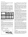
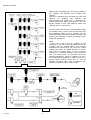
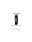
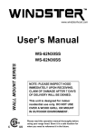
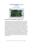
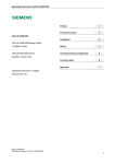
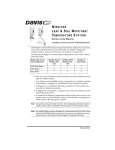
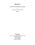
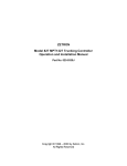
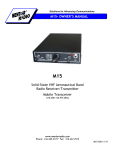
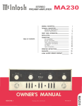
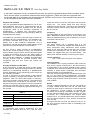
VMARS. S.R. Mk 2
Radio Link S.R. Mark II
Colin Guy, G4DDI
In last year’s members’ survey, we asked if there were any specific equipments about which members would
like to see an article; one member mentioned the above equipment. Earlier this year the equipment was
mentioned again in conversation with Howard Aspinall, G3RXH, and it is from a user manual kindly loaned to
me by Howard that this article has been compiled.
Purpose and Facilities
This is a specialised wireless apparatus for use in Gun
Sound Ranging, both for R.T. communications and for
transmission of gun-sound impulses from the special
microphone used, to the recording equipment at
Headquarters.
It replaces wire connections during
mobile operations, enabling the sound-ranging “Base” to
be deployed more quickly.
cases are used to house the set proper and the power
supply unit. The vehicle carrier and pack carrying
arrangements are identical. The bulk of the components
used are common to those used in either the W.S. No.18,
No.19 or No.22.
Frequency
The sets operate on the range from 9 to 10.5 Mc/s in one
band. Bandwidth required is 50 kc/s, 20 kc/s above and
below the allotted frequency plus an allowance of 10 kc/s
for drift and various errors.
The Radio Link consists of nine sets, eight of which are
outstations and one “Headquarters”. The outstations can
be remote controlled from a point up to half a mile
distant, and a self contained Loudspeaker Unit is
provided for use with the HQ set to enable plotting centre
personnel to monitor all speech communications.
Power Supply
The power supply unit is operated from a 6 volt
accumulator. HT and bias supplies are obtained from a
three commutator rotary transformer which supplies
60mA at 150 volts and 40mA at 40 volts. The unit also
contains the necessary R.F. and A.F. filtering. The valve
heaters are supplied from the 6 volt accumulator. The
battery drain whether sending or receiving is 6.5 amps.
An S.R. Troop in action consists of a Headquarters
(where gun sound recording is done), five microphone
posts to detect the gun sounds, and two advanced posts
to control the recording when once the “base” station is
established. R.T. communications are required between
H.Q. and all the outstations. In addition an independent
one-way channel must be provided between each
microphone post and H.Q. where gun sounds are
recorded.
Layout of Stations
Figs. 1 and 2 show the layout of the stations.
Tuning Systems.
The outstation has a 2-gang condenser which tunes the
M.O. circuit (1 section tunes the M.O., the other section is
a compensator for the channel spreading) and a 2-gang
condenser which tunes the receiver R.F. circuit and local
oscillator, 2 single section condensers tune the Buffer
stage and Aerial circuit independently.
The H.Q. set has 2 single section condensers which tune
the L.O. and Aerial circuits independently. The Buffer
stage is fixed tuned using a Band pass coil. The receiver
has a 2-gang condenser which tunes the R.F. circuit and
local oscillator.
Principle of Radio Link S.R. Mk.II
At the microphone, a single set serves for both speech
and gun sounds. When transmitting the latter, the sender
frequency is automatically altered by a predetermined
amount, depending on the channel being used. There are
five channels, see table 1.
At H.Q. a special set is used, having a multi channel
receiver consisting of a single local oscillator and five I.F.
amplifiers, which are tuned 10kc/s apart in frequency.
The centre channel is used for speech. The outputs from
these channels are connected to the Recorder. In this
way the off frequency transmissions from the microphone
senders are selected without mutual interference, and
are directed to the corresponding galvanometer strings of
the recorder.
Aerials.
The set is designed primarily for use with rod aerials 34’
in length. Aerials shorter than this can be used when
working at close range or where the 34’ aerial would be
too conspicuous. It must, however, be stressed that
successful film recording necessitates as high a signalto-noise ratio as possible; much more so than in the case
of ordinary R.T. communications. The longest aerial
possible (up to 34’) should therefore be used (consistent
with the tactical situation), when working at distances
over one mile.
At ranges less than one mile, the absence of A.V.C. on
the H.Q. receivers renders it liable to overloading from
the near station.
Table 1
Channel 1
Speech Frequency plus 20kc/s
Channel 2
Speech Frequency plus 10kc/s
Channel 3
No alteration in frequency
Channel 4
Speech Frequency minus 10 kc/s
Channel 5
Speech Frequency minus 20 kc/s
Construction
In construction and external appearance the sets
resemble the Wireless Sets No. 22 in that the same
C.J. Guy
1
VMARS. S.R. Mk 2
Fig. 1
Fig. 2
C.J. Guy
2
VMARS. S.R. Mk 2
The offending Outstation may have to use a reduced
aerial in these circumstances. Reduce by one section at
a time until the H.Q. is satisfied.
(ii)
Understand and carry out the netting drill
accurately, remembering that the H.Q. station is always
right and his instructions must always be obeyed
immediately.
When all stations have been netted, H.Q. calls each
microphone station in turn to “Press for S.R.,” using prearranged code. Before calling a given station, the H.Q.
“METER SWITCH” must be set to the corresponding
channel. As each station’s S.R. carrier is received, the
corresponding “CHANNEL SENSITIVITY” control is
adjusted to give a dip of 50 on the meter. For Channel 3,
the “SPEECH S.R.” switch must be pressed to throw the
Channel 3 control into circuit.
Units Loudspeaking No.1
This is provided for use at S.R. Troop headquarters to
enable the Plotting Centre personnel to monitor the
communication system without wearing headphones.
Also the officer in charge can talk to the HQ set operator
(who is wearing headphones) by means of a hand
microphone No.4 plugged into the loudspeaker unit. The
loudspeaker unit is plugged into the telephone jack on
the Recorder S.R., which is in turn connected through the
14-wire connecting cable to the intercommunications
systrem in the H.Q. set. The loudspeaker unit is
completely self – contained, requiring only a 6 volt
accumulator and hand microphone for working.
Weights and Dimensions
Weight
(lbs)
1
2
3
4
Senderreceiver
Power unit
Senderreceiver and
power unit on
carrier No. 1
Units
Loudspeaking
OS
HQ
32
35
21
21
67
Operation when Sound Ranging.
After establishing the net and adjusting channel
sensitivities, the system is ready to record gun-sounds. It
is assumed that the Recorder S.R. is ready, and that the
recorder operator has set the appropriate attenuators or
switches to the “R.L.” position.
(1) Location Shoots. H.Q. turns over control of the net to
one of the Advanced Posts, which then proceeds to give
the group call to find out if he is heard clearly by all other
stations. When a record is to be made, control sends
“SHOT” (or other pre-arranged code word) which is the
signal for all microphone stations to “PRESS FOR S.R.”
and for H.Q. to operate “SPEECH-S.R.” switch to “S.R.”
The switches will be held operated for a pre-arranged
time (say 30 seconds) to allow records to be received
from all channels. On releasing the switches, the net
returns to normal speech operation.
(2) Ranging Shoots. In this case, control remains with
H.Q. station, and the Advanced Posts “stand by.” The
instant of firing the ranging gun is reported to H.Q. by
telephone or otherwise, the time delay before sending
“SHOT” can be calculated from available data, and H.Q.
operator will be told when to give the signal.
Dimensions (ins)
Long
17 ½
Deep
High
13 ½
12
7
13 ½
8½
70
24
13 ½
14
16
6½
12
10 ½
Erecting the Aerial
Before you can operate the station a suitable aerial must
be erected and connected to the set. (See Figs. 1 and 2).
Operation
It doesn’t matter how good the wireless sets you are
using may be, you will not have good signals or good
recordings at H.Q. unless they are all accurately tuned to
the same frequency. This point is emphasised with all
communication equipment, but must be very strongly
emphasised with respect to the Radio Link S.R. Bringing
a group of stations on to the same frequency is called
“Netting,” and to do it successfully all the operators in the
group must:—
(i)
Know exactly how to tune the wireless set quickly
and with confidence. This has been described in the last
two sections.
Use of Remote Operating Units No. I.
The unit is carried inside the power supply unit, and is
intended to be employed at Advanced Posts where it
would be difficult to conceal the wireless station with its
aerial. The unit is used at the observer’s position, and is
connected to the set by one or more lengths of 6conductor rubber covered cable. When the station is set
up and netted, the cable is plugged into the “REMOTE
CONTROL” socket on the panel. The microphone and
headphones are disconnected from the set, and plugged
into the remote control unit at the Advanced Post. SendReceive switching is done by the pressel switch as
before, and no operator is required at the set except to
check the tuning, or to change frequency. A remote
operating unit is also carried in the H.Q. set to serve as a
spare.
Circuit Details
The outstation (fig. 3) receiver consists of R.F. amplifier
V1A (ARP12), local oscillator V1B (ARP12), mixer V1C
(ARP12),
IF
amplifier
V1D
(ARP12)
and
detector/avc/output V2A (AR8). The sender consists of
M.O. V3B (ARP34), buffer V4A (ATP4), P.A. V4B and
V4C (ATP4) and ranging microphone amplifier V3A
C.J. Guy
3
VMARS. S.R. Mk 2
(ARP34).The H.Q. station (fig. 4) receiver consists of
R.F. amplifier V3A (ARP12), local oscillator V2C
(ARP34)
and five I.F. amplifiers each consisting of a mixer V3B
(ARP12), I.F. amplifier V3C (ARP12) and
detector/output V4A (AR8). The I.F. amplifiers are
tuned to frequencies spaced 10 kc/s apart. The H.Q.
sender consists of M.O. V2B (ARP34), buffer V2A
(ARP34) and P.A. V3A (ATP4).
Six spare valves are carried in unwired holders inside
the outstation sets. It will be seen from the above that
this equipment shares much in common with the
WS22 and WS62, and anyone familiar with these sets
would have no difficulty in making an example of this
equipment operational.
Final
I have never come across an example of this
equipment “in the flesh”: my understanding is that, as
it doesn’t cover any amateur bands, most of those
examples that did find their way onto the surplus
market were broken for spares. However, if anyone
does have one tucked away, or has a technical
manual for it, I would be pleased to hear from them.
Also, the manual gives no information about the
recording equipment, except a reference to “film”,
which implies that it would be an “optical” recorder. If
anyone knows anything about this, or how the
resulting recordings were used to determine gun
positions an article would be most welcome.
Fig. 3
Fig. 4
C.J. Guy
4